Toyotomi HC-190 Service Manual
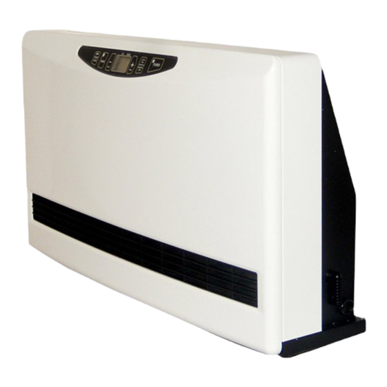
Heat convector
Hide thumbs
Also See for HC-190:
- Installation and operation instructions manual (20 pages) ,
- Mounting instructions (2 pages)
Table of Contents
Advertisement
Quick Links
Advertisement
Table of Contents

Related Manuals for Toyotomi HC-190


Summary of Contents for Toyotomi HC-190
- Page 1 SERVICE MANUAL HEAT CONVECTOR HC-190...
-
Page 2: Table Of Contents
CONTENTS SECTION 1: DESCRIPTION SPECIFICATIONS………………………..............1 DIMENSIONAL OUTLINE................... 2 OPERATING CONTROLS AND PART NAME............3 ACCESSORY PARTS ....................3 WIRING DIAGRAM..................... 4 OUTLINE OF OPERATION..................5 DESCRIPTION OF FUNCTIONAL COMPONENTS AND PARTS......6 SECTION 2: OPERATION & INSTALLATION OBSERVE THE FOLLOWING ITEMS FOR SAFE OPERATION......9 OPERATION...................... -
Page 3: Section 1: Description Specifications
SECTION 1: DESCRIPTION SPECIFICATIONS Model: HC-190 Type: Hot Water Heating, Floor Standing Type Heat Rating Range: 4,050 to 20,000 BTU/h (1.2 to 5.9 kW) *See the chart below for details. Max. Allowable Pressure: 142 PSI (0.98 MPa) Heat Exchanger Capacity: 0.16 gal. -
Page 4: Dimensional Outline
- 2 -... -
Page 5: Operating Controls And Part Name
OPERATING CONTROLS AND PART NAMES 1. POWER switch: Main switch turns the unit on or off. 2. AUTO/MANUAL button: Button switches fan speed to either AUTO and MANUAL. 3. TIMER button: Button turns Timer operation mode on or off. 4. CHILD LOCK button: The button turns CHILD LOCK operation mode on or off. -
Page 6: Wiring Diagram
WIRING DIAGRAM - 4 -... -
Page 7: Outline Of Operation
OUTLINE OF OPERATION Circulate the hot water and turn the unit ON, then, the motor start operating and revolve the fan in the case that the room temperature is lower than set temperature and then blow the hot air with the hot water heat that passed through inside the heat exchanger when you set the AUTO FAN MODE. -
Page 8: Description Of Functional Components And Parts
DESCRIPTION OF FUNCTIONAL COMPONENTS AND PARTS 1. Heat Exchanger Mainly, it is formed from the copper pipe at passing water part and aluminum fin for radiating heat, it is made compact and light, and also secured the durability. 〇If the fin is deformed, it may cause to reduce the air volume and output. - Page 9 3. Fan The cross flow fan for blowing hot air 4. Main circuit board (with electric current fuse) It controls fan and other functions depending on the operation condition and sensor value. 〇Confirm the wires whether they are connected correctly when the unit does not operate properly.
- Page 10 6. Room thermistor This thermistor is for detecting the room temperature, and also it has a feature that the resistance value changes depending on the room temperature. Celsius 0℃ 5℃ 10℃ 15℃ 20℃ 25℃ 30℃ Fahrenheit 32°F 41°F 50°F 59°F 68°F 77°F 86°F...
-
Page 11: Observe The Following Items For Safe Operation
SECTION 2: OPERATION OBSERVE THE FOLLOWING ITEMS FOR SAFE OPERATION The instructions which are contained in this manual are classified into the following two types, which are “WARNING” and “CAUTION”. These instructions are intended to provide important information for safe operation. “WARNING”... - Page 12 - 10 -...
- Page 13 - 11 -...
- Page 14 - 12 -...
-
Page 15: Test Run
TEST RUN PREPARATION 1. Make sure there is no water leaking from the unit and piping. 2. Make sure electrical connections and grounding are wired properly. 3. Check for air trapped in the plumbing. OPERATION 1. Plug into the receptacle. 2. -
Page 16: Routine Maintenance
ROUTINE MAINTENANCE CAUTION: Be sure to unplug the unit before performing any checks or cleaning. FOR OPTIMUM UNIT PERFORMANCE, THE PARTS SHOWN BELOW SHOULD BE CLEANED REGULARLY: 1. Clean Louvers (ONCE A MONTH) Dust and stains should be wiped off louvers with a damp cloth. 2. - Page 17 WARNING: This unit must be installed in accordance with these instructions, local codes, ordinances and/or in the absence of local codes National Plumbing standards. Check and comply with all state and local codes before beginning the installation. This unit should be installed by a licensed, authorized person(s) due to the necessity of making electrical and water connections.
- Page 18 PLUMBING NOTE: Make sure the piping for the unit is laid out properly, and also check for any water leakage Please use the two spanners to tighten the pipe connection. Use one spanner to fix the pipe connection, and use the other one to tighten the screws with the proper torque. CAUTION: DO NOT put a huge load on to the pipe connection.
- Page 19 PERMANENT WIRING INSTALLATION WARNING: TO AVOID ANY RISK OF FIRE AND ELECTRIC SHOCK. Make sure the Main circuit breaker and power supply cord is disconnected before servicing. Electric shock may cause serious injury. It is recommended that installation should be conducted by a Licensed Electrician. PROCEDURE FOR PERMANENT WIRING POWER SOURCE: 120V AC, 60Hz single phase 1.
- Page 20 EXTERNAL OUTPUT TERMINAL WIRING This unit has an External output terminal for low-voltage (24 volts or less) contacts to connected to a circulation pump control or zone valve. When connecting the circulation control or zone valve unit to this terminal, it is possible to stop the circulation by the output from internal contact switch in the Heat convector.
-
Page 21: Section 4: Disassembling
SECTION 4: DISASSEMBLING How to exchange the components B) How to exchange the transformer A)How to exchange the main circuit board (It takes approximately 10 minutes.) (It takes approximately 10 minutes.) After taking out the A-1)Remove both left front panel, remove and right side of the the 2 settled screws screws and move the... - Page 22 E) How to exchange the water temp. thermistor F-5) (It takes approximately 5 minutes.) After opening the lower Take out the plate frame to the left and spring which holds on right side a little and the water temp. taking out from the base, thermistor and then raise the frame to the take out the thermistor.
- Page 23 G) How to exchange the heat exchanger G-7) (It takes approximately 15 minutes. Remove the screws for ※After taking the unit out from the pipe.) the rear panel, and take ※When you take the unit apart, remove the out the rear panel connecting water pipe and drain the water from the pipe.
- Page 24 G-11) Remove the four (4) screws for the heat exchanger (two (2) screws at the each side), then remove the heat exchanger. H) How to remove the filter (It takes approximately 1 min.) Remove the filter after taking two (2) screws at the upper of the filter off.
-
Page 25: Time Chart
SECTION 5: TIME CHART [TIME CHART 1] FIG.1 NORMAL OPERATION(AUTO MODE) POWER SW (hour・-) SW (min.・+) SW TIMER SW CHILD LOCK SW AUTO FAN/MANUAL FAN POWER LAMP TIMER LAMP AUTO MARK MANUAL MARK DISPLAY CLOCK SET.TEMP./ROOM.TEMP. CLOCK WATER TERMISTOR ~100°F(38℃) 100°F~110°F(38℃~43℃)... - Page 26 [TIME CHART 2] NORMAL OPERATION(AUTO MODE) FIG.2 (Circulation Water Temperature Detection) POWER SW (hour・-) SW (min.・+) SW TIMER SW CHILD LOCK SW AUTO FAN/MANUAL FAN POWER LAMP TIMER LAMP AUTO MARK MANUAL MARK MARK SET.TEMP./ROOM.TEMP. DISPLAY E-40 E-40 SET.TEMP/ROOM.TEMP SET.TEMP/ROOM.TEMP 100°F~110°F WATER THERMISTOR ~100°F...
- Page 27 [TIME CHART 3] NORMAL OPERATION(AUTO MODE) FIG.3 POWER SW (hour・-) SW (min.・+) SW TIMER SW CHILD LOCK SW AUTO FAN/MANUAL FAN POWER LAMP TIMER LAMP AUTO MARK MANUAL MARK MARK SET.TEMP/ROOM.TEMP DISPLAY CLOCK WATER THERMISTOR 100°F~110°F(38℃~43℃) 110°F(43℃)~ ~100°F(38℃) +6°F(3℃) ● +4°F(2℃) +2°F(1℃) ●...
- Page 28 [TIME CHART 4] NORMAL OPERATION(MANUAL MODE) FIG.4 POWER SW Invalid (hour・-) SW Invalid (min.・+) SW TIMER SW CHILDLOCK SW AUTO FAN/MANUAL FAN POWER LAMP TIMER LAMP AUTO LAMP MANUAL LAMP LAMP Clock DISPLAY WATER THERMISTOR 100°F~110°F(38℃~43℃) ~100°F(38℃) 110°F(43℃)~ +6°F(3℃) +4°F(2℃) +2°F(1℃) SET.TEMP.
- Page 29 [TIME CHART 5] NORMAL OPERATION(MODE CHANGE) FIG.5 POWER SW (hour・-) SW (min.・+) SW TIMER SW CHILDLOCK SW AUTO FAN/MANUAL FAN POWER LAMP TIMER LAMP AUTO MARK MANUAL MARK MARK SET.TEMP/ROOM.TEMP DISPLAY SET.TEMP./ROOM.TEMP. SET.TEMP/ROOM.TEMP WATER THERMISTOR 110°F(43℃)~ ~100°F(38℃) 100°F~110°F(38℃~43℃) +6°F(3℃) +4°F(2℃) ◎...
- Page 30 [TIME CHART 6] NORMAL OPERATION(TIMER OPERATION) FIG.6 POWER SW More than 1s (hour・-) SW (Hour・+) SW TIMER SW CHILDLOCK SW AUTO FAN/MANUAL FAN TIMER SET TIME REACHING POWER LAMP TIMER LAMP AM LAMP PM LAMP LAMP AUTO LAMP MANUAL LAMP LAMP DISPLAY...
- Page 31 [TIME CHART 7] FIG.7 CHILDLOCK OPERATION Invalid POWER SW Invalid (hour・-) SW (min.・+) SW Invalid More than T10 More than T10 TIMER SW CHILDLOCK SW Invalid AUTO FAN/MANUAL FAN POWER LAMP TIMER LAMP ° ° AM LAMP PM LAMP LAMP AUTO...
- Page 32 [TIME CHART 8] FIG.8 WATER THERMISTOR OPEN WATER THERMISTOR SHORT CIRCUIT FREQENCY 45Hz<FREQENCY<65Hz 45Hz<FREQENCY<65Hz POWER SW (hour・-) SW (min.・+) SW TIMER SW CHILDLOCK SW AUTO FAN/MANUAL FAN POWER LAMP TIMER LAMP AM LAMP PM LAMP LAMP AUTO LAMP MANUAL LAMP LAMP DISPLAY...
- Page 33 [TIME CHART 9] SAFETY FUNCTION FIG.9 POWER FREQUENCY SAFETY FUNCTION FREQUENCY 45Hz≧FREQUENCY or FREQUENCY≧65Hz 45Hz<FREQUENCY<65Hz POWER SW (hour・-) SW (min.・+) SW TIMER SW CHILDLOCK SW AUTO FAN/MANUAL FAN SW POWER LAMP TIMER LAMP AM LAMP PM LAMP LAMP AUTO LAMP MANUAL...
- Page 34 [TIME CHART 10] FIG.10 OPERATION SW INPUT MALFUNCTION WHEN POWER IS ON FREQUENCY 45Hz<FREQUENCY<65Hz POWER SW (hour・-) SW (min.・+) SW TIMER SW CHILDLOCK SW AUTO FAN/MANUAL FAN SW POWER LAMP TIMER LAMP AM LAMP PM LAMP LAMP AUTO LAMP MANUAL LAMP LAMP DISPLAY...
- Page 35 [TIME CHART 11] FIG.11 ERROR BACKUP DISPLAY POWER MONITOR DISPLAY POWER SW (hour・-) SW (min.・+) SW TIMER SW CHILDLOCK SW AUTO FAN/MANUAL FAN SW POWER LAMP TIMER LAMP ° °LAMP AM LAMP PM LAMP LAMP AUTO LAMP MANUAL LAMP XX:Error display in order happened LAMP DISPLAY...
- Page 36 [TIME CHART 12] FIG.12 INSPECTION MODE FREQUENCY WITHIN T6 POWER SW (hour・-) SW (min.・+) SW TIMER SW CHILDLOCK SW AUTO FAN/MANUAL FAN SW POWER LAMP TIMER LAMP AM LAMP PM LAMP LAMP AUTO LAMP MANUAL LAMP LAMP DISPLAY 88:88 INSPECTION MODE DISPLAY --:-- WATER THERMISTOR +4°F(2℃)
- Page 37 [TIME CHART 13] FIG.10 ACTION AT THE TIME OF POWER FAILURE OFF POWER ON ON OFF ON POWER SW (hour・-) SW (min.・+) SW TIMER SW CHILDLOCK SW AUTO FAN/MANUAL FAN SW POWER LAMP TIMER LAMP AM LAMP PM LAMP LAMP AUTO...
-
Page 38: Section 6: Troubleshooting
SECTION 6: TROUBLESHOOTING Tools and Materials Required for Repair Phillips screwdriver Straight edge driver Vinyl insulating tape 0.4 inch (11 mm) wrench 0.5 inch (12 mm) wrench 0.7 inch (17 mm) wrench 0.8 inch (19 mm) wrench - 6 inch (150 mm) adjustable wrench 12 inch (300 mm) adjustable wrench Thermometer 32 to 212 °F (0 to 100°C) 15 inch (375 mm) adjustable wrench Pipe wrench Vernier calipers... - Page 39 TROUBLE SHOOTING (ERROR CODES) ERROR CHECK CONTENTS CONDITION REASON SOLUTION Check the resistance Under 3kΩ of Short-circuit of the The water thermistor detected ・The water ・Exchange the water E-03 value of the resistance value is Water thermistor under 3 kΩ of resistance value. thermistor failure thermistor.
- Page 40 TROUBLE SHOOTING (NO ERROR CODES) ERROR CAUSE CHECK SOLUTION ・Power outage. Check the power voltage. Correct the power voltage. Check whether the power plug is ・Power supply code is disconnected. Connect the power plug. connecting to wall socket or not. Exchange the fuse wire if there is ・Breaking of electric current fuse wire (Controller)...
-
Page 41: Parts Description
PARTS DESCRIPTION... - Page 42 HC-190 REF # PART # PART NAME 20477046 Front panel 20477032 Louver assembly 20477069 Fan motor assembly/ Capacitor 20477003 Fan capacitor 20477004 Fan cross assembly 20477017 Transformer 20477114 Heat exchanger assembly 20477074 Water temp. thermistor 20477012 Main circuit board 20478379...
- Page 43 TOYOTOMI U.S.A., INC. 604 Federal Road, Brookfield, CT 06804 New 10/21...