Dell Dimension E521 Owner's Manual
Dell dimension e521: owners manual
Hide thumbs
Also See for Dimension E521:
- Setting up (2 pages) ,
- Owner's manual (158 pages) ,
- Service manual (64 pages)
Table of Contents
Advertisement
Quick Links
CD or DVD eject button
CD or DVD activity light
FlexBay for optional
floppy drive or Media
Card Reader
microphone connector
headphone connector
diagnostic lights
hard-drive activity light
power button/
power activity light
USB 2.0 connectors (2)
Model DCSM
w w w . d e l l . c o m | s u p p o r t . d e l l . c o m
Dell™ Dimension™ E521
Owner's Manual
Service Tag
cover latch
release
Advertisement
Table of Contents
Troubleshooting

Related Manuals for Dell Dimension E521


Summary of Contents for Dell Dimension E521
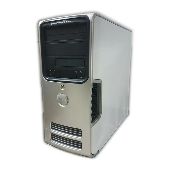
- Page 1 Dell™ Dimension™ E521 Service Tag CD or DVD eject button CD or DVD activity light FlexBay for optional floppy drive or Media Card Reader microphone connector headphone connector diagnostic lights hard-drive activity light power button/ power activity light USB 2.0 connectors (2) Model DCSM w w w .
-
Page 2: Abbreviations And Acronyms
PowerApp, DellNet, Dell TravelLite, Strike Zone, and PowerConnect are trademarks of Dell Inc.; Bluetooth is a registered trademark owned by Bluetooth SIG, Inc. and is used by Dell under license; Microsoft, Windows, and Outlook are registered trademarks of Microsoft Corporation;... -
Page 3: Table Of Contents
Contents Finding Information Setting Up and Using Your Computer Front View of the Computer Back View of the Computer Back Panel Connectors Setting Up a Printer Printer Cable ....... . Connecting a Printer Connecting to the Internet Setting Up Your Internet Connection... - Page 4 Power Management Standby Mode Hibernate Mode Power Options Properties Enabling Cool ’n’ Quiet™ Technology About RAID Configurations RAID Level 1 Configuration Configuring Your Hard Drives for RAID Using the Nvidia MediaShield ROM Utility Using Nvidia MediaShield Solving Problems Troubleshooting Tips Battery Problems .
- Page 5 Dell Diagnostics ....... . . Dell Diagnostics Main Menu Drivers .
- Page 6 Memory ........Memory Installation Guidelines Addressing Memory With 4-GB Configurations Installing Memory Removing Memory...
- Page 7 ....... Dell Technical Support Policy (U.S. Only) Definition of "Dell-Installed" Software and Peripherals Definition of "Third-Party"...
- Page 8 Contents...
-
Page 9: Finding Information
• Warranty information • Terms and Conditions (U.S. only) • Safety instructions • Regulatory information • Ergonomics information • End User License Agreement • How to set up my computer Find it Here Dell™ Product Information Guide Setup Diagram Finding Information... - Page 10 Select your region to view the appropriate support site. NOTE: Corporate, government, and education customers can also use the customized Dell Premier Support website at premier.support.dell.com. To download Desktop System Software: Go to support.dell.com and click Downloads. Enter your Service Tag or product model.
- Page 11 What Are You Looking For? • How to use Windows XP • How to work with programs and files • How to personalize my desktop Find it Here Windows Help and Support Center → Click Start Help and Support. Type a word or phrase that describes your problem and click the arrow icon.
- Page 12 Finding Information...
-
Page 13: Setting Up And Using Your Computer
Computer Cover" on page 66. Use the Service Tag to identify your computer when you access the Dell Support website or call technical support. Press to eject a disk from the CD or DVD drive. The drive light is on when the computer reads data from the CD or DVD drive. - Page 14 FlexBay drive microphone connector headphone connector diagnostic lights (4) hard-drive activity light power button, power light USB 2.0 connectors (2) vents Setting Up and Using Your Computer Can contain an optional floppy drive or optional Media Card Reader. For information on using the Media Card Reader, see "Using a Media Card Reader (Optional)"...
-
Page 15: Back View Of The Computer
Back View of the Computer voltage selection switch power connector back panel connectors card slots See the safety instructions in the Product Information Guide for more information. Insert the power cable. Plug USB, audio, and other devices into the appropriate connector. See "Back Panel Connectors"... -
Page 16: Back Panel Connectors
Back Panel Connectors link integrity light network adapter connector network activity light surround connector Setting Up and Using Your Computer • Green — A good connection exists between a 10-Mbps network and the computer. • Orange — A good connection exists between a 100-Mbps network and the computer. -
Page 17: Setting Up A Printer
line-in connector Use the blue line-in connector to attach a record/playback device such as a cassette player, CD player, or VCR. On computers with a sound card, use the connector on the card. line-out connector Use the green line-out connector (available on computers with integrated sound) to attach headphones and most speakers with integrated amplifiers. -
Page 18: Connecting A Printer
Connecting a Printer NOTE: You can connect USB devices while the computer is turned on. 1 Complete the operating system setup if you have not already done so. 2 Attach the USB printer cable to the USB connectors on the computer and the printer. The USB connectors fit only one way. -
Page 19: Setting Up Your Internet Connection
2 Double-click the ISP icon on the Microsoft 3 Follow the instructions on the screen to complete the setup. If you do not have an ISP icon on your desktop or if you want to set up an Internet connection with a different ISP: 1 Save and close any open files, and exit any open programs. -
Page 20: Playing Cds And Dvds
Playing CDs and DVDs NOTICE: Do not press down on the CD or DVD tray when you open or close it. Keep the tray closed when you are not using the drive. NOTICE: Do not move the computer when you are playing CDs or DVDs. 1 Press the eject button on the front of the drive. -
Page 21: Adjusting The Volume
A DVD player includes the following basic buttons: Stop Restart the current chapter Play Fast forward Pause Fast reverse Advance a single frame while in pause mode Go to the next title or chapter Continuously play the current title or chapter Go to the previous title or chapter Eject For more information on playing CDs or DVDs, click Help on the CD or DVD player (if available). -
Page 22: Copying Cds And Dvds
This section applies only to computers that have a CD-RW, DVD+/-RW, or CD-RW/DVD (combo) drive. NOTE: The types of CD or DVD drives offered by Dell may vary by country. The following instructions explain how to make an exact copy of a CD or DVD. You can also use Sonic DigitalMedia for other purposes, such as creating music CDs from audio files stored on your computer or backing up important data. -
Page 23: Helpful Tips
Blank DVD+/-Rs can be used to permanently store large amounts of information. After you create a DVD+/-R disc, you may not be able to write to that disc again if the disc is "finalized" or "closed" during the final stage of the disc creation process. Use blank DVD+/-RWs if you plan to erase, rewrite, or update information on that disc later. -
Page 24: Using A Media Card Reader (Optional)
• Use a blank CD-RW to practice CD recording until you are familiar with CD recording techniques. If you make a mistake, you can erase the data on the CD-RW and try again. You can also use blank CD-RWs to test music file projects before you record the project permanently to a blank CD-R. •... - Page 25 xD-Picture Card and SmartMedia (SMC) SecureDigital Card (SD)/ MultiMediaCard (MMC) To use the Media Card Reader: 1 Check the media or card to determine the proper orientation for insertion. 2 Slide the media or card into the appropriate slot until it is completely seated in the connector. If you encounter resistance, do not force the media or card.
-
Page 26: Connecting Two Monitors
Connecting Two Monitors CAUTION: Before you begin any of the procedures in this section, follow the safety instructions in the Product Information Guide. If you purchased a graphics card that supports dual monitors, follow these instructions to connect and enable your monitors. The instructions tell you how to connect either two monitors (each with a VGA connector), one monitor with a VGA connector and one monitor with a DVI connector, or a TV. -
Page 27: Connecting One Monitor With A Vga Connector And One Monitor With A Dvi Connector
In clone mode, both monitors display the same image. • In extended desktop mode, you can drag objects from one screen to the other, effectively doubling the amount of viewable work space. For information on changing the display settings for your graphics card, see the user’s guide in the Help and Support Center (click the Start button, click Help and Support, click User and system guides, click Device guides, and then click the guide for your graphics card). -
Page 28: Network Setup Wizard
When the computer exits from a power conservation mode, the Windows desktop is restored to the state it was in before it entered the mode. -
Page 29: Standby Mode
Because hibernate mode requires a special file on your hard drive with enough disk space to store the contents of the computer memory, Dell creates an appropriately sized hibernate mode file before shipping the computer to you. If the computer’s hard drive becomes corrupted, Windows XP recreates the hibernate file automatically. -
Page 30: Power Options Properties
Power Options Properties Define your standby mode settings, hibernate mode settings, and other power settings in the Power Options Properties window. To access the Power Options Properties window: 1 Click the Start button and click Control Panel. 2 Under Pick a category, click Performance and Maintenance. 3 Under or pick a Control Panel icon, click Power Options. -
Page 31: Enabling Cool 'N' Quiet™ Technology
Hibernate Tab The Hibernate tab allows you to enable hibernate mode. If you want to use the hibernate settings you defined on the Power Schemes tab, click the Enable hibernate support check box on the Hibernate tab. For more information on power management options: 1 Click the Start button and click Help and Support. -
Page 32: Configuring Your Hard Drives For Raid
If a drive failure occurs, subsequent read and write operations are directed to the surviving drive. A replacement drive can then be rebuilt using the data from the surviving drive. NOTE: In a RAID level 1 configuration, the size of the configuration is equal to the size of the smallest drive in the configuration. -
Page 33: Using The Nvidia Mediashield Rom Utility
3 Press <Ctrl><N> when prompted to enter the RAID BIOS. NOTE: If the operating system logo appears, continue to wait until you see the Microsoft Windows desktop, then shut down your computer and try again. The Define a New Array window appears. -
Page 34: Using Nvidia Mediashield
8 Press <Y> to clear all data from the selected drives. The Array List window appears. 9 To review the details of the array that you set up, use the arrow keys to highlight the array in the Array Detail window and press <Enter>. The Array Detail window appears. - Page 35 NOTICE: The Clear System Data option deletes all data on the selected drive. 9 Click Next. 10 Click Finish to create the RAID configuration. The MediaShield RAID management utility window appears and lists the array along with any other installed hard drives. Deleting a RAID Array NOTE: While this procedure deletes the RAID 1 volume, it also splits the RAID 1 volume into two non-RAID hard...
- Page 36 7 Click Finish. The MediaShield RAID management utility window appears and displays the status of the rebuild process. NOTE: You can use your computer while the computer is rebuilding the array. NOTE: You can use any available (RAID-enabled) free disk to rebuild an array. Setting Up and Using Your Computer...
-
Page 37: Solving Problems
— If you have to repeatedly reset time and date information after turning on the computer, or if an incorrect time or date displays during start-up, replace the battery (see "Replacing the Battery" on page 109). If the battery still does not work properly, contact Dell (see "Contacting Dell" on page 126). -
Page 38: Drive Problems
I N D O W S R E C O G N I Z E S T H E D R I V E — See "Resolving Software and Hardware Incompatibilities" — See "Dell Diagnostics" on page 56. — — Click the Start button and... -
Page 39: Hard Drive Problems
H E C K T H E S P E A K E R S A N D S U B W O O F E R Problems writing to a CD/DVD-RW drive L O S E O T H E R P R O G R A M S —... -
Page 40: Error Messages
H E C K T H E T E L E P H O N E L I N E C O N N E C T I O N H E C K T H E T E L E P H O N E J A C K O N N E C T T H E M O D E M D I R E C T L Y T O T H E T E L E P H O N E W A L L J A C K S E A D I F F E R E N T T E L E P H O N E L I N E •... -
Page 41: Keyboard Problems
I/O panel and to the system board and reboot your computer. If this does not resolve the problem or if you have an ultra small form- factor computer, contact Dell (see "Contacting Dell" on page 126). drive letter : \ I S N O T A C C E S S I B L E Insert a disk into the drive and try again. -
Page 42: Lockups And Software Problems
EST THE KEYBOARD — Connect a properly working keyboard to the computer, and try using the keyboard. N S U R E T H A T T H E P O R T S A R E E N A B L E D I N T H E S YS T E M S E T U P P R O G R A M Setup"... -
Page 43: A Program Crashes Repeatedly
A program crashes repeatedly NOTE: Software usually includes installation instructions in its documentation or on a floppy disk or CD. H E C K T H E S O F T W A R E D O C U M E N T A T I O N A program is designed for an earlier Microsoft U N T H E R O G R A M... -
Page 44: Media Card Reader Problems
A V E A N D C L O S E A N Y O P E N F I L E S O R P R O G R A M S A N D S H U T D O W N Y O U R C O M P U T E R T H R O U G H T H E S T A R T M E N U Media Card Reader Problems O D R I V E L E T T E R I S A S S I G N E D... -
Page 45: Memory Problems
• Run the Dell Diagnostics (see "Dell Diagnostics" on page 56). F Y O U E X P E R I E N C E O T H E R M E M O R Y P R O B L E M S •... -
Page 46: Network Problems
E S T A R T T H E C O M P U T E R — Simultaneously press <Ctrl><Esc> to display the Start menu. Type , press the keyboard arrow keys to highlight Shut down or Turn Off, and then press <Enter>. After the computer turns off, reconnect the mouse cable as shown on the on the setup diagram for your computer. -
Page 47: Power Problems
H E C K Y O U R N E T W O R K S E T T I N G S your network to verify that your network settings are correct and that the network is functioning. U N T H E A R D W A R E R O U B L E S H O O T E R on page 59. -
Page 48: Printer Problems
F T H E P O W E R L I G H T I S B L I N K I N G A M B E R internal power problem might exist. • Ensure that the voltage selection switch is set to match the AC power at your location (if applicable). See "Back View of the Computer"... -
Page 49: Scanner Problems
E R I F Y T H A T T H E P R I N T E R I S R E C O G N I Z E D B Y Click the Start button, click Control Panel, and then click Printers and Other Hardware. Click View installed printers or fax printers. -
Page 50: Sound And Speaker Problems
Sound and Speaker Problems CAUTION: Before you begin any of the procedures in this section, follow the safety instructions in the Product Information Guide. No sound from speakers NOTE: The volume control in some MP3 players overrides the Windows volume setting. If you have been listening to MP3 songs, ensure that you did not turn the player volume down or off. -
Page 51: No Sound From Headphones
No sound from headphones H E C K T H E H E A D P H O N E C A B L E C O N N E C T I O N into the headphone connector (see "Front View of the Computer" on page 13). D J U S T T H E I N D O W S V O L U M E C O N T R O L corner of your screen. -
Page 52: If The Screen Is Difficult To Read
If the screen is difficult to read H E C K T H E M O N I T O R S E T T I N G S contrast and brightness, demagnetizing (degaussing) the monitor, and running the monitor self-test. O V E T H E S U B W O O F E R A W A Y F R O M T H E M O N I T O R ensure that the subwoofer is at least 60 cm (2 ft) away from the monitor. -
Page 53: Troubleshooting Tools
• If available, install properly working memory of the same type into your computer (see "Installing Memory" on page 72). • If the problem persists, contact Dell (see "Contacting Dell" on page 126). Troubleshooting Tools... - Page 54 • If available, install properly working memory of the same type into your computer (see "Installing Memory" on page 72). • If the problem persists, contact Dell (see "Contacting Dell" on page 126). • Ensure that no special memory module/memory connector placement requirements exist (see "Memory...
- Page 55 (such as the floppy drive or hard drive), check the device to ensure that it is functioning properly. • If the problem persists, contact Dell (see "Contacting Dell" on page 126). None. Troubleshooting Tools...
-
Page 56: Dell Diagnostics
If you cannot resolve the error condition, contact Dell (see "Contacting Dell" on page 126). NOTE: The Service Tag for your computer is located at the top of each test screen. If you contact Dell, technical support will ask for your Service Tag. -
Page 57: Drivers
Parameters Allows you to customize the test by changing the test settings. 4 Close the test screen to return to the Main Menu screen. To exit the Dell Diagnostics and restart the computer, close the Main Menu screen. Drivers What Is a Driver? A driver is a program that controls a device such as a printer, mouse, or keyboard. -
Page 58: Identifying Drivers
Reinstalling Drivers NOTICE: The Dell Support website at support.dell.com provides approved drivers for Dell™ computers. If you install drivers obtained from other sources, your computer might not work correctly. Using Windows XP Device Driver Rollback If a problem occurs on your computer after you install or update a driver, use Windows XP Device Driver Rollback to replace the driver with the previously installed version. -
Page 59: Resolving Software And Hardware Incompatibilities
• Dell PC Restore by Symantec restores your hard drive to the operating state it was in when you purchased the computer. Dell PC Restore permanently deletes all data on the hard drive and removes any applications installed after you received the computer. Use PC Restore only if System Restore did not resolve your operating system problem. -
Page 60: Using Microsoft Windows Xp System Restore
NOTE: The procedures in this document were written for the Windows default view, so they may not apply if you set your Dell™ computer to the Windows Classic view. Creating a Restore Point 1 Click the Start button and click Help and Support. -
Page 61: Using Dell Pc Restore
Using Dell PC Restore NOTICE: Using Dell PC Restore permanently deletes all data on the hard drive and removes any applications or drivers installed after you received your computer. If possible, back up the data before using PC Restore. Use PC Restore only if System Restore did not resolve your operating system problem. - Page 62 NOTICE: Removing Dell PC Restore from the hard drive permanently deletes the PC Restore utility from your computer. After you have removed Dell PC Restore, you will not be able to use it to restore your computer’s operating system. Dell PC Restore enables you to restore your hard drive to the operating state it was in when you purchased your computer.
-
Page 63: Using The Operating System Cd
The Operating System CD provides options for reinstalling Windows XP. The options can overwrite files and possibly affect programs installed on your hard drive. Therefore, do not reinstall Windows XP unless a Dell technical support representative instructs you to do so. - Page 64 Troubleshooting Tools...
-
Page 65: Removing And Installing Parts
You have performed the steps in Turning Off Your Computer and Before Working Inside Your Computer. • You have read the safety information in your Dell™ Product Information Guide. • A component can be replaced or—if purchased separately—installed by performing the removal procedure in reverse order. -
Page 66: Before Working Inside Your Computer
NOTICE: Only a certified service technician should perform repairs on your computer. Damage due to servicing that is not authorized by Dell is not covered by your warranty. NOTICE: When you disconnect a cable, pull on its connector or on its strain-relief loop, not on the cable itself. - Page 67 NOTICE: Ensure that you are working on a level, protected surface to avoid scratching either the computer or the surface on which it is resting. 2 Lay your computer on its side with the computer cover facing up. 3 Pull back the cover latch release located on the top panel. cover latch release bottom hinge tabs 4 Grip the sides of the computer cover and pivot the cover up, using the bottom hinge tabs as leverage...
-
Page 68: Inside View Of Your Computer
Inside View of Your Computer CAUTION: Before you begin any of the procedures in this section, follow the safety instructions in the Product Information Guide. *May not be present on all computers. floppy drive or Media Reader system board Removing and Installing Parts CD or DVD drive hard drive power supply... -
Page 69: System Board Components
System Board Components fan connector (FAN_CPU1) power connector (PW_12V_A1) front-panel connector (FRONTPANEL) processor socket (CPU) serial ATA drive connectors (SATA2, SATA3) power connector (POWER1) memory module connectors (DIMM_1, DIMM_2, DIMM_3, DIMM_4) serial ATA drive connectors (SATA0, SATA1) line-in, line-out, microphone, side surround, center, and LFE connectors (AUDIO_6_STACK) -
Page 70: Memory
10 USB connectors (2) (USB2_BACK1) 13 video connector (VIDEO1) 16 PCI Express x16 connector (SLOT1) 19 PCI connector (SLOT3) 22 floppy drive connector (FLOPPY1) Memory You can increase your computer memory by installing memory modules on the system board. Your computer supports DDR2 memory. -
Page 71: Memory Installation Guidelines
If you remove your original memory modules from the computer during a memory upgrade, keep them separate from any new modules that you may have, even if you purchased the new modules from Dell. If possible, do not pair an original memory module with a new memory module. Otherwise, your computer may not start properly. -
Page 72: Addressing Memory With 4-Gb Configurations
Addressing Memory With 4-GB Configurations Your computer supports a maximum of 4 GB of memory when you use four 1-GB DIMMs. Current 32-bit operating systems, such as Microsoft space; however, the amount of memory available to the operating system is less than that installed. Certain components within the computer require address space in the 4-GB range. - Page 73 3 Align the notch on the bottom of the module with the crossbar in the connector. cutouts (2) crossbar NOTICE: To avoid damage to the memory module, press the module straight down into the connector while you apply equal force to each end of the module. 4 Insert the module into the connector until the module snaps into position.
-
Page 74: Removing Memory
You can do so by touching an unpainted metal surface on the computer chassis. Your Dell™ computer provides the following slots for PCI and PCI Express cards: • One PCI Express x16 card slot (SLOT1) •... - Page 75 Installing a PCI Card 1 Follow the procedures in "Before You Begin" on page 65. release tab 2 Gently push the release tab on the card retention door from the inside to pivot the door open. Because the door is captive, it will remain in the open position. 3 If you are installing a new card, remove the filler bracket to create a card-slot opening.
- Page 76 6 Place the card in the connector and press down firmly. Ensure that the card is fully seated in the slot. alignment bar alignment guide 7 Before you close the card retention door, ensure that: • The tops of all cards and filler brackets are flush with the alignment bar. •...
- Page 77 alignment guide card retention door 8 Close the card retention door by snapping it into place to secure the cards. NOTICE: Do not route card cables over or behind the cards. Cables routed over the cards can prevent the computer cover from closing properly or cause damage to the equipment. 9 Connect any cables that should be attached to the card.
- Page 78 front I/O panel connector sound card connector If you are installing a sound card, remove the jumper on the end of the front I/O panel. Then connect one end of the cable to the sound card and the other end of the cable to the connection on the front I/O panel from which you removed the jumper.
- Page 79 12 If you installed an add-in network adapter and want to disable the integrated network adapter: Enter system setup (see "System Setup" on page 115), go to Onboard Devices and select Integrated NIC, and then change the setting to Off. Connect the network cable to the add-in network adapter’s connectors.
-
Page 80: Pci Express Cards
PCI Express Cards Your computer supports one PCI Express x16 card and one PCI Express x1 card. • If you are installing or replacing a PCI Express card, follow the procedures in the next section. • If you are removing but not replacing a card, see "Removing a PCI Express Card" on page 85. •... - Page 81 6 If you are replacing a card that is already installed in the computer, remove the card. Disconnect any cables connected to the card. Gently pull the securing tab, grasp the card by its top corners, and then ease it out of its connector. PCI Express x16 card PCI Express x1 card slot 7 Prepare the card for installation.
- Page 82 9 Place the card in the connector and press down firmly. Ensure that the card is fully seated in the slot. alignment bar alignment guide 10 If you replaced a card that was already installed in the computer and you removed the retention mechanism, reinstall the retention mechanism: Before replacing the card retention mechanism, ensure that: •...
- Page 83 card retention door NOTICE: Do not route card cables over or behind the cards. Cables routed over the cards can prevent the computer cover from closing properly or cause damage to the equipment. NOTICE: To connect a network cable, first plug the cable into the network device and then plug it into the computer. 11 Before you close the card retention door, ensure that: •...
- Page 84 alignment guide card retention door 12 Close the card retention door by snapping it into place to secure the cards. 13 Connect any cables that should be attached to the card. See the documentation for the card for information about the card’s cable connections. 14 Replace the computer cover, reconnect the computer and devices to electrical outlets, and then turn them on.
- Page 85 Connect the network cable to the add-in network adapter’s connectors. Do not connect the network cable to the integrated connector on the back panel. See "Back Panel Connectors" on page 16. 17 Install any drivers required for the card as described in the card documentation. Removing a PCI Express Card 1 Follow the procedures in "Before You Begin"...
-
Page 86: Drive Panel
Drive Panel CAUTION: Before you begin any of the procedures in this section, follow the safety instructions in the Product Information Guide. CAUTION: To guard against electrical shock, always unplug your computer from the electrical outlet before removing the cover. Removing the Drive Panel 1 Follow the procedures in "Before You Begin"... -
Page 87: Removing The Drive-Panel Insert
3 Grasping the lever on the sliding plate, pull the sliding plate to the right until it snaps into the open position. NOTE: This sliding plate secures and releases the drive panel and helps to secure the drives. 4 By pushing from the inside and pivoting the drive panel to the left, you can release the drive panel from its side hinges. -
Page 88: Replacing The Drive-Panel Insert
Replacing the Drive-Panel Insert center drive-panel tab drive-panel insert 1 Slide the tab on the left side of the drive-panel insert under the center drive-panel tab. 2 Rotate the drive-panel insert into place and snap the drive-panel insert tab over the corresponding tab on the drive panel. -
Page 89: Replacing The Drive Panel
Replacing the Drive Panel 1 Align the drive panel tabs with the side hinges. sliding plate lever drive panel tabs (3) 2 Rotate the drive panel toward the computer until it snaps into place on the front panel. sliding plate side hinges drive panel Removing and Installing Parts... -
Page 90: Drives
Drives Your computer supports a combination of these devices: • Up to two serial ATA hard drives • One optional floppy drive or an optional Media Card Reader • Up to two CD or DVD drives CD/DVD drive Recommended Drive Cable Connections •... -
Page 91: Connecting Drive Cables
Connecting Drive Cables When you install a drive, you connect two cables—a DC power cable and a data cable—to the back of the drive. Power Connector power cable Drive Interface Connectors The drive cable connectors are keyed for correct insertion. Properly align the cable connector key on the cable and the drive before connecting. -
Page 92: Hard Drives
Hard Drives CAUTION: Before you begin any of the procedures in this section, follow the safety instructions in the Product Information Guide. CAUTION: To guard against electrical shock, always unplug your computer from the electrical outlet before removing the cover. NOTICE: To avoid damage to the drive, do not set it on a hard surface. -
Page 93: Installing A Hard Drive
3 Press in on the blue tabs on each side of the drive and slide the drive up and out of the computer. tabs (2) 4 If removing this drive changes the drive configuration, then be sure to reflect these changes in system setup. - Page 94 drive 4 Align the hard drive bracket with the guides in the hard drive bay. hard-drive bracket 5 Gently slide the drive into place until you feel a click or the drive is securely installed. Take care not to let the drive free-fall into the drive bay. 6 Connect the power and data cables to the drive.
-
Page 95: Adding A Second Hard Drive
serial ATA data cable 7 Check all cables to be certain that they are properly connected and firmly seated. 8 Replace the computer cover (see "Replacing the Computer Cover" on page 110). NOTICE: To connect a network cable, first plug the cable into the network port or device and then plug it into the computer. - Page 96 NOTICE: To avoid damage to the drive, do not set it on a hard surface. Instead, set the drive on a surface, such as a foam pad, that will sufficiently cushion it. 1 Check the documentation for the drive to verify that it is configured for your computer. 2 Follow the procedures in "Before You Begin"...
-
Page 97: Floppy Drive
Floppy Drive CAUTION: Before you begin any of the procedures in this section, follow the safety instructions in the Product Information Guide. CAUTION: To guard against electrical shock, always unplug your computer from the electrical outlet before removing the cover. NOTE: If you are adding a floppy drive, see "Installing a Floppy Drive"... - Page 98 4 Slide the drive latch release toward the bottom of the computer and, without releasing the drive latch release, slide the floppy drive out through the front of the computer. drive latch release 5 If you are not replacing the drive, reinstall the drive panel insert (see "Replacing the Drive-Panel Insert" on page 88).
-
Page 99: Installing A Floppy Drive
Installing a Floppy Drive NOTE: In the event that the replacement or new floppy drive does not have shoulder screws, check for the screws located within the drive panel insert or, if applicable, reuse screws attached to the drive that you are replacing. drive 1 Follow the procedures in "Before You Begin"... - Page 100 power cable 6 If you are installing a new floppy drive rather than replacing a drive, remove the appropriate drive-panel insert (see "Removing the Drive-Panel Insert" on page 87). 7 Check all cable connections, and fold cables out of the way to avoid blocking airflow between the fan and cooling vents.
-
Page 101: Media Card Reader
11 Enter system setup (see "System Setup" on page 115) and select the appropriate Diskette Drive option. 12 Verify that your computer works correctly by running the Dell Diagnostics (see "Dell Diagnostics" on page 56). Media Card Reader CAUTION: Before you begin any of the procedures in this section, follow the safety instructions in the Product Information Guide. - Page 102 3 Disconnect the FlexBay USB cable from the back of the Media Card Reader and from the internal USB connector on the system board (see "System Board Components" on page 69) and remove the cable from the cable routing clip. drive latch release 4 Slide the drive latch release toward the bottom of the computer and, without releasing the drive latch release, slide the Media Card Reader out through the front of the computer.
-
Page 103: Installing A Media Card Reader
Installing a Media Card Reader NOTE: In the event that the replacement or new Media Card Reader does not have shoulder screws, use the screws located within the drive panel insert. Otherwise, reuse the screws attached to the card reader that you are replacing. -
Page 104: Cd/Dvd Drive
6 Connect the FlexBay USB cable to the back of the Media Card Reader and to the internal USB connector on the system board (see "System Board Components" on page 69). Media Card Reader 7 Route the FlexBay USB cable through the cable routing clip. 8 Replace the computer cover (see "Replacing the Computer Cover"... -
Page 105: Removing A Cd/Dvd Drive
Removing a CD/DVD Drive 1 Follow the procedures in "Before You Begin" on page 65. 2 Remove the drive panel (see "Removing the Drive Panel" on page 86). 3 Disconnect the power cable and the CD/DVD drive data cable from the back of the drive and the system board. - Page 106 4 Slide the drive latch release toward the bottom of the computer and, without releasing the drive latch release, slide the CD/DVD drive out through the front of the computer. 5 If you are not replacing the drive, replace the drive panel insert (see "Replacing the Drive-Panel Insert" on page 88).
-
Page 107: Installing A Cd/Dvd Drive
Installing a CD/DVD Drive NOTE: In the event that the replacement or new CD/DVD drive does not have shoulder screws, check for the screws located within the drive panel insert or, if applicable, reuse screws attached to the drive that you are replacing. - Page 108 9 Enter system setup (see "System Setup" on page 115) and select the appropriate Drive option. 10 Verify that your computer works correctly by running the Dell Diagnostics (see "Dell Diagnostics" on page 56). Removing and Installing Parts...
-
Page 109: Battery
Battery Replacing the Battery CAUTION: Before you begin any of the procedures in this section, follow the safety instructions in the Product Information Guide. NOTICE: To prevent static damage to components inside your computer, discharge static electricity from your body before you touch any of your computer’s electronic components. You can do so by touching an unpainted metal surface on the computer chassis. -
Page 110: Replacing The Computer Cover
NOTICE: To connect a network cable, first plug the cable into the network device and then plug it into the computer. 8 Connect your computer and devices to electrical outlets, and then turn them on. 9 Enter system setup (see "System Setup" on page 115) and restore the settings you recorded in step 1. Then go to the Maintenance section and clear the low battery and other errors associated with the battery replacement in the Event Log. -
Page 111: Appendix
Appendix Specifications Processor Processor type Level 2 (L2) cache Memory Type Memory connectors Memory capacities Minimum memory Maximum memory Computer Information Chipset RAID Support DMA channels Interrupt levels BIOS chip (NVRAM) Video Type AMD Athlon 64 X2 dual-core processor AMD Athlon 64 processor AMD Sempron processor Up to 1 MB per core Up to 256 KB for Sempron processors... - Page 112 Audio Type Expansion Bus Bus type Bus speed connectors connector size connector data width (maximum) PCI Express connector connector size connector data width (maximum) PCI Express connector connector size connector data width (maximum) Drives Externally accessible: Bays Available devices Internally accessible: Appendix Sigmatel 9227 CODEC (7.1 Channel audio) PCI 2.3...
- Page 113 Connectors External connectors: Video Network adapter Audio System board connectors: Serial ATA Internal USB device Floppy drive PCI 2.3 PCI Express x1 PCI Express x16 Front panel Processor Memory Power 12V Power Controls and Lights Front of computer: Power button Power light Diagnostic lights Standby power light...
- Page 114 Controls and Lights (continued) Rear of computer: Link integrity light (on integrated network adapter) Network activity light (on integrated network adapter) Power DC power supply: Wattage Maximum heat dissipation Voltage (see the safety instructions located in the Product Information Guide for important voltage setting information) Backup battery Physical...
-
Page 115: System Setup
Entering System Setup 1 Turn on (or restart) your computer. 2 When the blue DELL™ logo is displayed, you must watch for the F2 prompt to appear. 3 Once this F2 prompt appears, press <F2> immediately. NOTE: The F2 prompt indicates that the keyboard has initialized. -
Page 116: System Setup Options
System Setup Options NOTE: Depending on your computer and installed devices, the items listed in this section may not appear, or may not appear exactly as listed. System Displays the System name, BIOS Version, Service Tag, Express Service Code, System Info and Asset Tag. - Page 117 The field configures the operating mode of the integrated hard drive SATA Operation controller. (Off default) • RAID Off — No RAID support • RAID On — SATA is configured for RAID on every boot. This setting determines whether integrated drive errors are reported or not SMART Reporting during system startup.
- Page 118 Performance • Bypass — Your computer does not test or change the current acoustics mode HDD Acoustic Mode Bypass default • Quiet — The hard drive operates at its most quiet setting. • Suggested — The hard drive operates at the level suggested by the drive •...
- Page 119 Sets the computer to automatically turn on. Auto Power On • Off — disables the Auto Power On feature (Off default) • Everyday — turns the computer on every day at the time set in Auto Power Time • Weekdays — turns the computer on every day from Monday through Friday at the time set in Auto Power Time NOTE: strip or surge protector.
-
Page 120: Boot Sequence
Determines the functionality of the numeric keys on the right side of your Numlock Key keyboard. (On default) • Off — commands the right keypad keys to function as arrows • On — commands the right keypad keys to function as numbers Determines whether the sign-on screen displays a message stating the POST Hotkeys keystroke sequence that is required to enter the Setup program or the... - Page 121 <F12>. If you wait too long and the operating system logo appears, continue to wait until you see the Microsoft Windows desktop, then shut down your computer (see "Turning Off Your Computer" on page 65) and try again. 4 Press <F1> to continue.
-
Page 122: Clearing Forgotten Passwords
9 Locate the 2-pin password jumper (PSWD) on the system board (see "System Board Components" on page 69) and attach the jumper to pins 1 and 2 to reenable the password feature. Appendix ® desktop appears on your computer, shut down the computer (see... -
Page 123: Clearing Cmos Settings
10 Close the computer cover (see "Replacing the Computer Cover" on page 110). NOTICE: To connect a network cable, first plug the cable into the network device and then plug it into the computer. 11 Connect your computer and devices to electrical outlets, and turn them on. Clearing CMOS Settings CAUTION: Before you begin any of the procedures in this section, follow the safety instructions located in the... -
Page 124: Mouse
NOTICE: Do not wipe the display screen with any soap or alcohol solution. Doing so may damage the antiglare coating. • To clean your monitor screen, lightly dampen a soft, clean cloth with water. If possible, use a special screen-cleaning tissue or solution suitable for the monitor’s antistatic coating. •... -
Page 125: Dell Technical Support Policy (U.s. Only)
All Dell-standard components included in a Custom Factory Integration (CFI) project are covered by the standard Dell lim- ited warranty for your computer. However, Dell also extends a parts replacement program to cover all nonstandard, third-party hardware components integrated through CFI for the duration of the computer’s service contract. -
Page 126: Contacting Dell
2 This device must accept any interference received, including interference that may cause undesired operation. NOTICE: The FCC regulations provide that changes or modifications not expressly approved by Dell Inc. could void your authority to operate this equipment. These limits are designed to provide reasonable protection against harmful interference in a residential installation. - Page 127 International Access Code: 00 E-mail for Desktops and Portables Country Code: 54 E-mail for Servers and EMC Products City Code: 11 Customer Service Technical Support – Dell PowerApp™, Dell PowerEdge™, Dell PowerConnect™, and Dell PowerVault™ Technical Support Services Sales Aruba Online Support...
- Page 128 City Code: 2 Customer Service Corporate Sales Switchboard Appendix Area Codes, Local Numbers, and Toll-Free Numbers Web and E-mail Address support.ap.dell.com support.ap.dell.com/contactus toll-free: 1300-655-533 toll-free: 1800-633-559 toll-free: 1800-060-889 toll-free: 1300-662-196 support.euro.dell.com tech_support_central_europe@dell.co 08 20 24 05 30 00 08 20 24 05 30 49...
- Page 129 Brunei Technical Support (Penang, Malaysia) Country Code: 673 Customer Service (Penang, Malaysia) Transaction Sales (Penang, Malaysia) Area Codes, Local Numbers, and Toll-Free Numbers Web and E-mail Address www.dell.com/bm la-techsupport@dell.com 1-877-890-0751 www.dell.com/bo la-techsupport@dell.com toll-free: 800-10-0238 www.dell.com/br BR_TechSupport@dell.com 0800 970 3355 51 2104 5470...
- Page 130 Online Support Country Code: 56 City Code: 2 Sales and Customer Support Appendix Area Codes, Local Numbers, and Toll-Free Numbers Web and E-mail Address www.dell.ca/ostatus support.ca.dell.com toll-free: 1-800-247-9362 toll-free: 1-800-847-4096 toll-free: 1-800-906-3355 toll-free: 1-800-387-5757 toll-free: 1-800-847-4096 toll-free: 1-800-387-5757 1-877-335-5767 toll-free: 1-800-999-3355...
- Page 131 City Code: 592 Customer Service E-mail Technical Support Fax Technical Support – Dell™ Dimension™ and Dell Inspiron™ Technical Support – Dell OptiPlex™, Dell Latitude™, and Dell Precision™ Technical Support – Servers and Storage Technical Support – Projectors, PDAs, Switches, Routers, etc.
- Page 132 Technical Support, Customer Service, Sales (calling from Quito) Technical Support, Customer Service, Sales (calling from Guayaquil) Appendix Area Codes, Local Numbers, and Toll-Free Numbers Web and E-mail Address www.dell.com/cr la-techsupport@dell.com 0800-012-0231 support.euro.dell.com czech_dell@dell.com 22537 2727 22537 2707 22537 2714 22537 2728 22537 2711 support.euro.dell.com...
- Page 133 Fax (calls from outside of France) Corporate Technical Support Customer Service Switchboard Sales Area Codes, Local Numbers, and Toll-Free Numbers Web and E-mail Address www.dell.com/sv la-techsupport@dell.com 800-6132 support.euro.dell.com fi_support@dell.com 0207 533 555 0207 533 538 0207 533 533 0207 533 530 0207 533 540 0207 533 533 support.euro.dell.com...
- Page 134 Technical Support, Customer Service, Sales Guyana Online Support Technical Support, Customer Service, Sales Appendix Area Codes, Local Numbers, and Toll-Free Numbers Web and E-mail Address support.euro.dell.com tech_support_central_europe@dell.co 069 9792-7200 0180-5-224400 069 9792-7320 069 9792-7320 069 9792-7320 069 9792-7320 069 9792-7000 support.euro.dell.com...
- Page 135 International Access Code: 001 Country Code: 852 Technical Support – Dimension and Inspiron Technical Support – OptiPlex, Latitude, and Dell Precision Technical Support – Servers and Storage Technical Support – Projectors, PDAs, Switches, Routers, etc. Customer Service Large Corporate Accounts...
- Page 136 Sales Large Corporate Accounts Home and Small Business Appendix Area Codes, Local Numbers, and Toll-Free Numbers Web and E-mail Address support.ap.dell.com india_support_desktop@dell.com india_support_notebook@dell.com 080-25068032 or 080-25068034 or your city STD code + 60003355 or toll-free: 1-800-425-8045 india_support_Server@dell.com 080-25068032 or 080-25068034...
- Page 137 Corporate Customer Service (dial within U.K. only) U.K. Sales (dial within U.K. only) Area Codes, Local Numbers, and Toll-Free Numbers Web and E-mail Address support.euro.dell.com dell_direct_support@dell.com 1850 543 543 1850 543 543 1850 200 889 1850 333 200 1850 664 656...
- Page 138 (dial from within Jamaica only) Appendix Area Codes, Local Numbers, and Toll-Free Numbers Web and E-mail Address support.euro.dell.com 02 577 826 90 02 696 821 14 02 696 821 13 02 696 821 12 02 577 826 90 02 577 825 55...
- Page 139 Technical Support outside of Japan – City Code: 44 Dimension and Inspiron Technical Support – Dell Precision, OptiPlex, and Latitude Technical Support outside of Japan – Dell Precision, OptiPlex, and Latitude Technical Support – Dell PowerApp, Dell PowerEdge, Dell PowerConnect, and Dell PowerVault Technical Support outside of Japan –...
- Page 140 Home/Small Business Sales Corporate Sales Customer Service Malaysia (Penang) Online Support International Access Code: 00 Technical Support – Dell Precision, OptiPlex, and Latitude Country Code: 60 Technical Support – Dimension, Inspiron, City Code: 4 and Electronics and Accessories Technical Support – PowerApp, PowerEdge,...
- Page 141 Country Code: 64 Technical Support, Customer Service, Sales Nicaragua Online Support Technical Support, Customer Service, Sales Area Codes, Local Numbers, and Toll-Free Numbers Web and E-mail Address www.dell.com/mx la-techsupport@dell.com 001-866-563-4425 50-81-8800 or 001-800-888-3355 001-877-384-8979 or 001-877-269-3383 50-81-8800 or 001-800-888-3355 or 001-866-851-1754 la-techsupport@dell.com...
- Page 142 Customer Service Sales Puerto Rico Online Support Technical Support Customer Service and Sales Appendix Area Codes, Local Numbers, and Toll-Free Numbers Web and E-mail Address support.euro.dell.com 671 16882 671 17575 23162298 671 16800 671 16865 www.dell.com/pa la-techsupport@dell.com 011-800-507-1264 www.dell.com/pe la-techsupport@dell.com 0800-50-669 support.euro.dell.com...
- Page 143 Malaysia only. Country Code: 65 Online Support Technical Support – Dimension, Inspiron, and Electronics and Accessories Technical Support – OptiPlex, Latitude, and Dell Precision Technical Support – PowerApp, PowerEdge, PowerConnect, and PowerVault Customer Service Transaction Sales Corporate Sales Slovakia (Prague)
- Page 144 Employee Purchase Program (EPP) Support Technical Support Fax Sales Appendix Area Codes, Local Numbers, and Toll-Free Numbers Web and E-mail Address support.euro.dell.com dell_za_support@dell.com 011 709 7713 011 709 7710 011 709 7707 011 709 7700 011 706 0495 011 709 7700 604 633 4810 support.euro.dell.com...
- Page 145 Technical Support – Servers and Storage Customer Service Transaction Sales Corporate Sales Thailand Online Support International Access Code: 001 Technical Support (OptiPlex, Latitude, and Dell Precision) Country Code: 66 Technical Support (PowerApp, PowerEdge, PowerConnect, and PowerVault) Customer Service Corporate Sales Transaction Sales Trinidad/Tobago...
- Page 146 Preferred Accounts (500–5000 employees) Global Accounts Central Government Local Government & Education Health Technical Support Corporate/Preferred Accounts/PCA (1000+ employees) Other Dell Products General Home and Small Business Fax Uruguay Online Support Technical Support, Customer Service, Sales Appendix Local Numbers, and...
- Page 147 Country (City) Service Type International Access Code Country Code City Code U.S.A. (Austin, Texas) Dell Services for the Deaf, Hard-of-Hearing, or Speech-Impaired International Access Code: 011 Country Code: 1 Technical Support Home and Home Office Portable and Desktop AutoTech Small Business...
- Page 148 Country Code City Code U.S. Virgin Islands Online Support Technical Support, Customer Service, Sales Venezuela Online Support Technical Support, Customer Service, Sales Appendix Area Codes, Local Numbers, and Toll-Free Numbers Web and E-mail Address www.dell.com/vi la-techsupport@dell.com toll-free: 1-877-702-4360 www.dell.com/ve la-techsupport@dell.com 0800-100-4752...
-
Page 149: Glossary
Glossary Terms in this Glossary are provided for informational purposes only and may or may not describe features included with your particular computer. AC — alternating current — The form of electricity that powers your computer when you plug the AC adapter power cable in to an electrical outlet. - Page 150 bus — A communication pathway between the components in your computer. bus speed — The speed, given in MHz, that indicates how fast a bus can transfer information. byte — The basic data unit used by your computer. A byte is usually equal to 8 bits.
- Page 151 PCI Express and USB 2.0 standard. Express Service Code — A numeric code located on a sticker on your Dell™ computer. Use the Express Service Code when contacting Dell for assistance. Express Service Code service may not be available in some countries.
- Page 152 extended display mode — A display setting that allows you to use a second monitor as an extension of your display. Also referred to as dual display mode. extended PC Card — A PC Card that extends beyond the edge of the PC Card slot when installed. Fahrenheit —...
- Page 153 — A bay that supports devices such as optical drives, a second battery, or a Dell TravelLite™ module. memory — A temporary data storage area inside your computer. Because the data in memory is not permanent,...
- Page 154 while you are working on them, and always save your files before you shut down the computer. Your computer can contain several different forms of memory, such as RAM, ROM, and video memory. Frequently, the word memory is used as a synonym for RAM. memory address —...
- Page 155 PCMCIA — Personal Computer Memory Card International Association — The organization that establishes standards for PC Cards. PIO — programmed input/output — A method of transferring data between two devices through the processor as part of the data path. pixel — A single point on a display screen. Pixels are arranged in rows and columns to create an image.
- Page 156 Service Tag — A bar code label on your computer that identifies your computer when you access Dell Support at support.dell.com or when you call Dell for customer service or technical support.
- Page 157 SXGA+ — super-extended graphics array plus — A video standard for video cards and controllers that supports resolutions up to 1400 x 1050. system board — The main circuit board in your computer. Also known as the motherboard. system setup — A utility that serves as an interface between the computer hardware and the operating system.
- Page 158 66-WHr battery can supply 66 W of power for 1 hour or 33 W for 2 hours. wallpaper — The background pattern or picture on the Windows desktop. Change your wallpaper through the Windows Control Panel. You can also scan in your favorite picture and make it wallpaper.
-
Page 159: Index
68 restore to previous state, 59-60 stops responding, 42 connectors headphone, 14 microphone, 14 USB, 14 contacting Dell, 126 copying CDs general information, 22 helpful tips, 23 how to, 22 copying DVDs general information, 22 helpful tips, 23... - Page 160 97 hard drive activity light, 14 installing, 93 installing second, 95 problems, 39 removing, 92 hardware Dell Diagnostics, 56 Hardware Troubleshooter, 59 headphone connector, 14 Help and Support Center, 11 help file Windows Help and Support Center, 11 hibernate mode, 29, 31...
- Page 161 37 blue screen, 43 CD drive, 38 CD-RW drive, 39 computer crashes, 42-43 computer stops responding, 42 Dell Diagnostics, 56 diagnostic lights, 53 drives, 38 DVD drive, 38 e-mail, 39 error messages, 40 general, 42 hard drive, 39...
- Page 162 112 memory, 111 physical, 114 power, 114 processor, 111 technical, 111 video, 111 standby mode, 29 support contacting Dell, 126 policy, 125 support website, 10 system board, 69 System Restore, 59-60 system setup about, 115 entering, 115 options, 116...
- Page 163 Windows XP (continued) Program Compatibility Wizard, 43 reinstalling, 60 scanner, 49 System Restore, 59-60 wizards Files and Settings Transfer Wizard, 31 Network Setup Wizard, 28 Program Compatibility Wizard, 43 Index...
- Page 164 Index...