Advertisement
OPERATING MANUAL
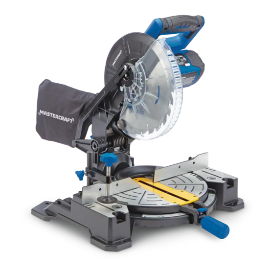
10" COMPOUND MITRE SAW
WITH LASER LINE AND STAND
55-6863-0
Parts missing or damaged? Questions? Toll-Free Help Line – 1-800-689-9928
IMPORTANT:
Read through this operating manual carefully before using this tool. Pay close
attention to all Safety Instructions, Warnings, and Caution sections. Use this tool
properly and only for its intended use.
Safety symbols in this manual are used to call attention to possible dangers.
The safety symbols and their explanations require the operator's full understanding.
The safety warnings do not, by themselves, eliminate any danger, nor are they a
substitute for proper accident-prevention measures.
This Safety Alert Symbol indicates caution, warning, or danger. Failure to obey
a safety warning can result in serious injury to the operator or to others. To reduce
the risk of injury, fire, or electric shock, always follow the safety precautions.
1
Advertisement
Table of Contents

Related Manuals for MasterCraft 55-6863-0


Summary of Contents for MasterCraft 55-6863-0
- Page 1 OPERATING MANUAL 10” COMPOUND MITRE SAW WITH LASER LINE AND STAND 55-6863-0 Parts missing or damaged? Questions? Toll-Free Help Line – 1-800-689-9928 IMPORTANT: Read through this operating manual carefully before using this tool. Pay close attention to all Safety Instructions, Warnings, and Caution sections. Use this tool properly and only for its intended use.
-
Page 2: Table Of Contents
TABLE OF CONTENTS Rules for Safe Operation……………………………. Page 3-8 Glossary of Woodworking Terms……………………Page 9 Description…………………………………….....Page 9-11 Assembly……………………..……..... Page 12-16 Adjustments............. Page 17 Operation....………………….....Page 18-24 Maintenance............Page 25 Troubleshooting............Page 26 Repair Parts.............Page 27 Exploded View & Part List........Page 28-30 Warranty………………………………………………..Page 31 SPECIFICATIONS Mitre Saw Specifications:... -
Page 3: Rules For Safe Operation
RULES FOR SAFE OPERATION KNOW THE TOOL To operate this tool safely, carefully read this operating manual and all the labels affixed to the Compound Mitre Saw and Stand before using it, and follow all instructions contained therein. Retain this manual for future reference. MPORTANT This tool should only be serviced by a qualified service technician. - Page 4 GENERAL SAFETY PRECAUTIONS Read and become familiar with the entire Operating Manual. Learn the tool’s application, limitations, and possible hazards. Keep the guard in place and in working order. Remove all adjusting tools before turning tools on. Form the habit of checking to see that keys and adjusting wrenches are removed from the tool before turning the tool ON.
- Page 5 Check for damaged parts. Before further use of the tool, a guard or other part that is damaged should be carefully checked to determine that it will operate properly and perform its intended function. Check for alignment of moving parts, binding of moving parts, breakage of parts, mounting, and any other conditions that may affect the operation of the tool.
- Page 6 ELECTRICAL SAFETY Ground instruction: In the event of a malfunction or breakdown, grounding provides a path of least resistance for electric current to reduce the risk of electric shock. This tool is equipped with an electric cord having an equipment-grounding conductor and a grounding plug.
- Page 7 SPECIFIC SAFETY RULES Use only crosscutting saw blades. When using carbide-tipped blades, make sure that they have a negative hook angle. IMPORTANT: Do not use thin-kerf blades. Thin-kerf blades can deflect and contact the guard, which can cause possible injury to the operator. Do not operate the Mitre Saw until it is completely assembled and installed according to these instructions.
- Page 8 Make sure that the work area is clean before leaving the tool. Should any part of this Compound Mitre Saw be missing, damaged, or fail in any way, or should any electrical component fail to perform properly, shut off the power switch and remove the plug from the power-supply outlet.
-
Page 9: Glossary Of Woodworking Terms
GLOSSARY OF TERMS FOR WOODWORKING • Arbour: The revolving shaft on which a blade or cutting tool is mounted. • Arbour Lock: Allows the user to stop the blade from rotating while tightening or loosening the arbour screw during blade replacement or removal. •... -
Page 10: Description
DESCRIPTION KNOW THE COMPOUND MITRE SAW (See Fig. 1) Before attempting to use this Compound Mitre Saw, become familiar with all its operating features and safety requirements. Fig.1 ON/OFF trigger switch Horizontal, rubberized D-handle Safety lock-off button Upper blade guard Blade-screw guard Dust-extraction port Saw blade... - Page 11 KNOW THE MITRE-SAW STAND (See Fig. 2) Before attempting to use the Mitre-Saw Stand, become familiar with all its operating features and safety requirements. Fig. 2 Spring-Loaded Locking Pin Notch Tabletop-Assembly Clamping Knobs Chrome Extension Bars Carrying/Locking Handle Rubber Foot Pads Tabletop Assembly Table Assembly Supporting Bar Base Support Bar...
-
Page 12: Assembly
ASSEMBLY UNFOLDING AND SETTING UP THE MITRE-SAW STAND After taking the Mitre-Saw Stand out of carton, place it flat on floor, as shown (Fig.3). Fig. 3 Hold the yellow Locking/Carrying Handle (5) and the right side of the Table Assembly (7), and unlock the yellow Locking/Carrying Handle (5) by pulling the handle towards the operator... - Page 13 With one foot still on the Base Bar, lower the Table Top Assembly onto the Support Bar (8), while making sure that the Support Bar is placed into the Notch (2) (Fig. 10). Pull the Spring-Loaded Locking Pin (1) back so that the Support Bar and Tabletop groove fit together securely, then release the Spring-Loaded Locking Pin so that the Table Top is locked into position (Fig.
- Page 14 MOUNTNG THE MITRE SAW TO THE STAND (Fig.16) 1. Check the Mitre Saw for the number of mounting holes and their location. 2. Choose the corresponding hole locations on the Tabletop Assembly of the Mitre-Saw Stand. 3. Change the width of the Tabletop Assembly, if necessary, to accommodate the Mitre Saw.
- Page 15 Installation of adapter for shop vacuum Remove the dust extraction port for the dust bag by removing the two screws that hold it in place. Attach the shop-vacuum adapter with the same two screws. Release and lock the saw head Fig.
- Page 16 Installing the blade IMPORTANT: Do not use thin-kerf blades. Thin-kerf blades can deflect and contact the guard, which can cause injury to the operator. 1. Unplug the saw 2. Ensure that the inner flange is properly installed 3. Match the arrow on the blade with the arrow on the upper blade guard. Make sure that the blade teeth are pointing downward.
-
Page 17: Adjustments
ADJUSTMENT WARNING: To avoid possible injury, disconnect the tool’s plug from the power source before performing any assembly, adjustment, or repair. IMPORTANT: Do not use thin-kerf blades. Thin-kerf blades can deflect and contact the guard, which can cause injury to the operator. Mitre adjustment Lock the saw head in the down position, and loosen the mitre-lock knob. -
Page 18: Operation
OPERATION WARNING: To reduce the risk of injury, wear safety goggles or glasses with side shields. WARNING: Before each use, check that the blade is free from cracks, loose teeth, missing teeth, or any other damage. Do not use if damage is noticed or suspected. - Page 19 Support the work piece WARNING: Never use the help of another person as a substitute for a table extension, as support for a work piece that is longer or wider than the basic mitre table. Never have another person help feed, support, or pull the work piece instead of using table extensions.
- Page 20 Hold the work piece firmly against the fence. Keep hands in position until the ON/OFF trigger switch has been released and the blade has completely stopped. Start the Compound Mitre Saw WARNING: Always hold the cutting handle firmly, because the starting and stopping action of the motor may cause the handle to move up or down slightly.
- Page 21 6. Once the mitre angle is set, tighten the mitre-lock lever by tightening the mitre-lock knob. 7. Pull out the locking pin to release the saw arm. 8. Place the work piece flat on the mitre table with one edge securely against the fence.
- Page 22 To Bevel Cut With the Mitre Saw 1. Unplug the saw. WARNING: Failure to unplug the saw could result in accidental starting, causing serious injury. 2. Make sure that the mitre table is at 0°and locked, and check that the mitre-table lock is locked and secured in position.
- Page 23 CAUTION: Always perform a “dry run” cut to determine if the operation being attempted is possible before power is applied to Mitre Saw. COMPOUND MITRE CUTTING (Fig. 30) A compound mitre cut is a cut made using a mitre angle and a bevel angle at the same time.
- Page 24 9. Once the saw arm has been set at the desired angle, securely tighten the bevel-lock knob. 10. Place the work piece flat on the mitre table with one edge securely against the fence. If the board is warped, place the convex side against the fence. If the concave edge of the board is against the fence, the board could collapse on the blade at the end of the cut and jam the blade (Figs.
-
Page 25: Maintenance
MAINTENANCE Before cleaning or performing any maintenance, make sure that the Mitre Saw has been disconnected from the power supply. Keep all ventilation openings clean. Avoid using solvents when cleaning plastic parts. Most plastics are susceptible to damage from various types of commercial solvents and may be damaged by their use. Use a clean cloth to remove dirt, oil and grease. -
Page 26: Troubleshooting
TROUBLESHOOTING PROBLEM PROBABLE CAUSE SUGGESTED CORRECTIVE ACTION Brake does not stop blade within Electric hand brake has failed Take saw for servicing 6 seconds Motor brake overheated from Use a recommended blade use of defective or wrong size blade or rapid ON/OFF cycling Arbour bolt is loose Retighten Motor does not start... -
Page 27: Repair Parts
Repair Parts INCLUDES: • 1 Pc of 40T carbide tip blades • 1 pc of hold down clamp • 1 pc of dust collection bag • 1 pair of extension rails • 1 pc wrench • 1 pc vacuum adapter... - Page 29 Parts List Name Quantity Name Quantity Name Quantity Screw Gear case cover 125 Safety plate Motor cover Spring washer 126 Spring washer Screw Screw 127 Screw Brush Blade flange inner 128 Spring washer Brush spring Blade 129 Screw Brush hold Blade flange outer 130 Detent Screw...
- Page 30 Fixed guard Big washer Needle bearing Turntable C clip Screw Gear Spring washer Gear washer Washer Miter pointer Spindle Clamp plate Bearing Spring washer Screw Screw...
-
Page 31: Warranty
MASTERCRAFT LIMITED WARRANTY This Mastercraft® product is guaranteed three (3) years from the date of original retail purchase] against defects in materials and workmanship. Subject to the conditions and limitations described below, this product, if returned to us with proof of purchase within the stated warranty period and if covered under this warranty, will be repaired or replaced (with the same model, or one of equal value or specification), at our option.