Table of Contents
Advertisement
Quick Links
The
LM5164-Q1 EVM
high conversion efficiency in a small footprint. The EVM operates over a wide input voltage range of 15 V
to 100 V to provide a regulated 12-V output at 300-kHz switching frequency. The output voltage has better
than 1.5% setpoint accuracy and is adjustable using an external resistor divider. The module design uses
the
LM5164-Q1
synchronous buck converter with wide input voltage (wide V
range, integrated high-side and low-side power MOSFETs, cycle-by-cycle overcurrent protection, and
precision enable. With AEC-Q100 grade 1 automotive qualification, the LM5164-Q1 is rated to operate
over a junction temperature range of –40°C to +150°C. The LM5164-Q1 is available in an 8-pin SO
PowerPAD™ package to enable high density, low component count DC/DC solutions. The LM5164-
Q1EVM-041 evaluation module is qualified for the LM5164 as well as the LM5164-Q1 buck converter. See
Table 1
for package information.
Use the LM5164-Q1 with
the user can download the LM5164-Q1
examine predicted efficiency performance across line and load ranges.
CONVERTER
U1
SNVU620A – September 2018 – Revised April 2019
Submit Documentation Feedback
is a 100-V DC/DC buck regulator that employs synchronous rectification to achieve
WEBENCH® Power Designer
Quickstart calculator
Table 1. Device and Package Configurations
IC
LM5164-Q1
8-pin SO package with PowerPAD (4.89 mm × 3.90 mm)
LM5164
Copyright © 2018–2019, Texas Instruments Incorporated
SNVU620A – September 2018 – Revised April 2019
LM5164-Q1 EVM User Guide
to create a custom regulator design. Furthermore,
to optimize component selection and
PACKAGE
LM5164-Q1 EVM User Guide
User's Guide
) range, wide duty-cycle
IN
1
Advertisement
Table of Contents

Related Manuals for Texas Instruments LM5164-Q1 EVM


Summary of Contents for Texas Instruments LM5164-Q1 EVM
-
Page 1: Device And Package Configurations
Table 1. Device and Package Configurations CONVERTER PACKAGE LM5164-Q1 8-pin SO package with PowerPAD (4.89 mm × 3.90 mm) LM5164 SNVU620A – September 2018 – Revised April 2019 LM5164-Q1 EVM User Guide Submit Documentation Feedback Copyright © 2018–2019, Texas Instruments Incorporated... -
Page 2: Table Of Contents
EVM Electrical Performance Characteristics ..................LM5164-Q1 EVM Bill of Materials Trademarks PowerPAD is a trademark of Texas Instruments. All other trademarks are the property of their respective owners. LM5164-Q1 EVM User Guide SNVU620A – September 2018 – Revised April 2019 Submit Documentation Feedback Copyright ©... -
Page 3: General Ti High Voltage Evaluation User Safety Guidelines
Any other use and/or application are strictly prohibited by Texas Instruments. If you are not suitably qualified, you should immediately stop from further use of the HV EVM. - Page 4 Board should be handled with care by a professional. For safety, use of isolated test equipment with overvoltage and overcurrent protection is highly recommended. LM5164-Q1 EVM User Guide SNVU620A – September 2018 – Revised April 2019 Submit Documentation Feedback Copyright © 2018–2019, Texas Instruments Incorporated...
-
Page 5: Overview
453 k: 47 PF 56 pF 100 k: PGOOD 49.9 k: Copyright © 2018, Texas Instruments Incorporated Figure 2. LM5164-Q1 Buck Regulator Simplified Schematic Typical Applications • Automotive 48-V Mild Hybrid ECU Bias Supplies • Automotive DC/DC Converter, PTC Heater, HVAC Compressors •... - Page 6 Programmable input UVLO via precision enable (internally set to turn on and off at 1.5 V and 1.4 V, respectively) • Fully assembled, tested and proven PCB layout LM5164-Q1 EVM User Guide SNVU620A – September 2018 – Revised April 2019 Submit Documentation Feedback Copyright © 2018–2019, Texas Instruments Incorporated...
-
Page 7: Evm Characteristics
The default output voltage of this EVM is 12 V. Efficiency and other performance metrics will change based on the operating input voltage, output voltage, load current, output capacitance, and other parameters. LM5164-Q1 Evaluation Module The LM5164-Q1 EVM is configured to deliver 12 V and 1 A at a switching frequency of 300 kHz. As shown in Figure 2, a type 3 ripple generation circuit is used to generate the appropriate voltage ripple on FB. -
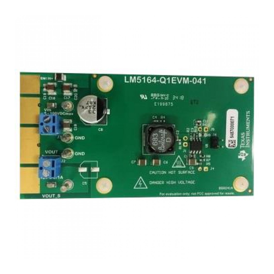
Page 8: Lm5164-Q1 Evm Top View
LM5164-Q1 Evaluation Module www.ti.com Figure 3. LM5164-Q1 EVM Top View CAUTION Caution Hot surface. Contact may cause burns. Do not touch. Detailed Descriptions This section describes the connectors and the test points on the EVM and how to properly connect, set up and use the LM5164-Q1 EVM. - Page 9 VIN, VOUT, and GND. See the schematic in Figure 4 for all signals connected to the edge connector. SNVU620A – September 2018 – Revised April 2019 LM5164-Q1 EVM User Guide Submit Documentation Feedback Copyright © 2018–2019, Texas Instruments Incorporated...
-
Page 10: Schematic
LM5164QDDARQ1 VOUT VOUT VOUT VOUT VIN_EMI 15uH 100k 4.7uF 0.1µF 4.7uF 0.1µF 4.7uF GND_EMI Figure 4. LM5164-Q1 EVM Schematic LM5164-Q1 EVM User Guide SNVU620A – September 2018 – Revised April 2019 Submit Documentation Feedback Copyright © 2018–2019, Texas Instruments Incorporated... -
Page 11: Pcb Layout
The 12-pin edge connector can also be used to facilitate the use of a cable harness if required. Figure 5. Top Layer and Silkscreen Layer Figure 6. Mid-Layer 1 Ground Plane SNVU620A – September 2018 – Revised April 2019 LM5164-Q1 EVM User Guide Submit Documentation Feedback Copyright © 2018–2019, Texas Instruments Incorporated... -
Page 12: Mid-Layer 2 Routing
PCB Layout www.ti.com Figure 7. Mid-Layer 2 Routing Figure 8. Bottom Layer Routing LM5164-Q1 EVM User Guide SNVU620A – September 2018 – Revised April 2019 Submit Documentation Feedback Copyright © 2018–2019, Texas Instruments Incorporated... -
Page 13: Bill Of Materials
Bill of Materials www.ti.com Bill of Materials Table 3. LM5164-Q1 EVM Bill of Materials Ref Des Value Description Package Part Number Vendor C1, C19, 0.1µF CAP, CERM, 0.1 µF, 100 V, ±10%, X7R, 0603 HMK107B7104KAHT Taiyo AEC-Q200 Grade 1, 0603... -
Page 14: Performance Curves
= 24 V Load = 1 A Figure 13. No Load Start-up with VIN Figure 14. Full Load Start-up with VIN LM5164-Q1 EVM User Guide SNVU620A – September 2018 – Revised April 2019 Submit Documentation Feedback Copyright © 2018–2019, Texas Instruments Incorporated... -
Page 15: Load Switching
Load = 0 A to Short to 0 A Figure 19. Short-Circuit Recovery Figure 20. No-Load/Short Circuit and Short-Circuit Recovery SNVU620A – September 2018 – Revised April 2019 LM5164-Q1 EVM User Guide Submit Documentation Feedback Copyright © 2018–2019, Texas Instruments Incorporated... -
Page 16: Cispr 25 Class 5 Conducted Emissions Plot, 150 Khz To 30 Mhz
Load = 1 A = 48 V Load = 1 A Figure 23. Thermal Performance Figure 24. Thermal Performance LM5164-Q1 EVM User Guide SNVU620A – September 2018 – Revised April 2019 Submit Documentation Feedback Copyright © 2018–2019, Texas Instruments Incorporated... - Page 17 Figure 28. CISPR 25 Class 5 Conducted Emissions Plot, 150 kHz to 30 MHz 30 MHz to 108 MHz SNVU620A – September 2018 – Revised April 2019 LM5164-Q1 EVM User Guide Submit Documentation Feedback Copyright © 2018–2019, Texas Instruments Incorporated...
- Page 18 Page ....................... • Updated EVM schematic .................... • Cleaned up BOM, added second sources ......................• Added CISPR 25 EMI figures Revision History SNVU620A – September 2018 – Revised April 2019 Submit Documentation Feedback Copyright © 2018–2019, Texas Instruments Incorporated...
- Page 19 STANDARD TERMS FOR EVALUATION MODULES Delivery: TI delivers TI evaluation boards, kits, or modules, including any accompanying demonstration software, components, and/or documentation which may be provided together or separately (collectively, an “EVM” or “EVMs”) to the User (“User”) in accordance with the terms set forth herein.
- Page 20 www.ti.com Regulatory Notices: 3.1 United States 3.1.1 Notice applicable to EVMs not FCC-Approved: FCC NOTICE: This kit is designed to allow product developers to evaluate electronic components, circuitry, or software associated with the kit to determine whether to incorporate such items in a finished product and software developers to write software applications for use with the end product.
- Page 21 www.ti.com Concernant les EVMs avec antennes détachables Conformément à la réglementation d'Industrie Canada, le présent émetteur radio peut fonctionner avec une antenne d'un type et d'un gain maximal (ou inférieur) approuvé pour l'émetteur par Industrie Canada. Dans le but de réduire les risques de brouillage radioélectrique à...
- Page 22 www.ti.com EVM Use Restrictions and Warnings: 4.1 EVMS ARE NOT FOR USE IN FUNCTIONAL SAFETY AND/OR SAFETY CRITICAL EVALUATIONS, INCLUDING BUT NOT LIMITED TO EVALUATIONS OF LIFE SUPPORT APPLICATIONS. 4.2 User must read and apply the user guide and other available documentation provided by TI regarding the EVM prior to handling or using the EVM, including without limitation any warning or restriction notices.
- Page 23 Notwithstanding the foregoing, any judgment may be enforced in any United States or foreign court, and TI may seek injunctive relief in any United States or foreign court. Mailing Address: Texas Instruments, Post Office Box 655303, Dallas, Texas 75265 Copyright © 2019, Texas Instruments Incorporated...
- Page 24 TI products. TI’s provision of these resources does not expand or otherwise alter TI’s applicable warranties or warranty disclaimers for TI products. Mailing Address: Texas Instruments, Post Office Box 655303, Dallas, Texas 75265 Copyright © 2019, Texas Instruments Incorporated...