Table of Contents
Advertisement
Quick Links
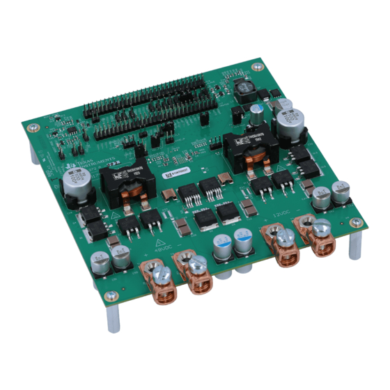
The LM5170EVM-BIDIR Evaluation Module (EVM) is designed to showcase the LM5170-Q1 high
performance dual-channel bidirectional controller suitable for, but not limited to, the automotive 48-V to 12-
V dual battery system applications.
The EVM can be configured to achieve a bidirectional power converter in the form of either the current
source or voltage source. The direction of power flow can be controlled either by an external command
signal or by the on-board jumper. Through the onboard interface headers, the EVM can be operated by a
DSP, an FPGA, an MCU, or other digital controllers. Two EVMs can be paralleled to make a 3 or 4
phases interleaved converter for higher power. More EVMs can be paralleled for greater number of
phases. Many convenient jumper headers are also included for versatile configurations of the EVM.
Refer to the
LM5170-Q1 Multiphase Bidirectional Current Controller Datasheet
technical information of the LM5170-Q1 device.
1
..........................................................................................................................
2
3
....................................................................................................................
4
.................................................................................................................
5
1
2
3
4
5
6
7
8
9
10
11
12
13
14
15
16
17
18
19
20
21
22
23
SNVU543A - November 2016 - Revised December 2016
.....................................................................................
.............................................................................................................
.................................................................................................
....................................................................................
..............................................................................................
...............................................................................
.......................................................................................
...............................................................................................
.........................................................................................................
........................................................................................................
..................................................................................
.................................................................................
........................................................................................
......................................................................................
..................................................................................................
.....................................................................................
Copyright © 2016, Texas Instruments Incorporated
SNVU543A - November 2016 - Revised December 2016
LM5170-Q1 EVM User Guide
Contents
List of Figures
.............................................................................
= 14.5 V
..............................................................
.............................................................
...........................................
...........................................
..................................................
..................................................
User's Guide
(SNVSAQ6) for detailed
..........................................
.........................................
LM5170-Q1 EVM User Guide
3
4
12
14
19
5
6
11
14
14
14
14
14
14
15
15
15
15
15
15
16
16
16
16
16
17
17
17
1
Advertisement
Table of Contents

Related Manuals for Texas Instruments LM5170-Q1 EVM


Summary of Contents for Texas Instruments LM5170-Q1 EVM
-
Page 1: Table Of Contents
Step Load Response: Buck Mode; 20-A to 50-A Load Step 1A/μs ..........Step Load Response: Boost Mode, 5-A to 10-A Load Step 1A/μs SNVU543A – November 2016 – Revised December 2016 LM5170-Q1 EVM User Guide Submit Documentation Feedback Copyright © 2016, Texas Instruments Incorporated... - Page 2 ....................Two-Pin Header Settings .................... J17 60-Pin Header Description ................... J18 60-Pin Header Description ......................Bill of Materials Trademarks LM5170-Q1 EVM User Guide SNVU543A – November 2016 – Revised December 2016 Submit Documentation Feedback Copyright © 2016, Texas Instruments Incorporated...
-
Page 3: Features And Electrical Performance
– Optional Channel Current Shunt AC Filters for Accurate DVM Reading (Unpopulated). The electrical performance of the EVM is show in Table Figure 1 shows the simplified EVM schematic. SNVU543A – November 2016 – Revised December 2016 LM5170-Q1 EVM User Guide Submit Documentation Feedback Copyright © 2016, Texas Instruments Incorporated... -
Page 4: Setup
Individual channel current monitoring or total current monitoring • Programmable undervoltage lockout (unpopulated) • Synchronization to external clock • External shutdown command through nFAULT pin (J17-pin45) LM5170-Q1 EVM User Guide SNVU543A – November 2016 – Revised December 2016 Submit Documentation Feedback Copyright © 2016, Texas Instruments Incorporated... -
Page 5: Simplified Evm Schematic
9.09 k AGND 0.22 µF 4.7 µH 470 µF 100 µF PGND PGND PGND Figure 1. Simplified EVM Schematic SNVU543A – November 2016 – Revised December 2016 LM5170-Q1 EVM User Guide Submit Documentation Feedback Copyright © 2016, Texas Instruments Incorporated... -
Page 6: Evm Board Top View And Layout Partitions
Setup www.ti.com Figure 2. EVM Board Top View and Layout Partitions LM5170-Q1 EVM User Guide SNVU543A – November 2016 – Revised December 2016 Submit Documentation Feedback Copyright © 2016, Texas Instruments Incorporated... -
Page 7: Three-Pin Header Settings
– = All jumper pins open. (1,2) = Pins 1 and 2 closed. (2,3) = Pins 2 and 3 closed. SNVU543A – November 2016 – Revised December 2016 LM5170-Q1 EVM User Guide Submit Documentation Feedback Copyright © 2016, Texas Instruments Incorporated... -
Page 8: Two-Pin Header Settings
Analog outer voltage loop control enabled Analog outer voltage loop control disabled Analog outer voltage loop control enabled Jumper pins open. Jumper pins closed. LM5170-Q1 EVM User Guide SNVU543A – November 2016 – Revised December 2016 Submit Documentation Feedback Copyright © 2016, Texas Instruments Incorporated... -
Page 9: J17 60-Pin Header Description
J17 is the interface connector to MCU, or external digital controller, or to the master EVM’s J18 if the host EVM serves as a slave in the multiphase configuration. I = input pin O = output pin SNVU543A – November 2016 – Revised December 2016 LM5170-Q1 EVM User Guide Submit Documentation Feedback Copyright © 2016, Texas Instruments Incorporated... -
Page 10: J18 60-Pin Header Description
J18 to the slave EVM’s J17. I = input pin O = output pin LM5170-Q1 EVM User Guide SNVU543A – November 2016 – Revised December 2016 Submit Documentation Feedback Copyright © 2016, Texas Instruments Incorporated... -
Page 11: Bidirectional Converter Bench Setup
50 A is required to monitor the inductor current via a wire loop inserted to the non-switching side of the inductor. SNVU543A – November 2016 – Revised December 2016 LM5170-Q1 EVM User Guide Submit Documentation Feedback Copyright © 2016, Texas Instruments Incorporated... -
Page 12: Test Procedure
7. After the tests are done, turn off the ISETA or ISETD signal, remove the voltage at J17-pin 5, and turn off the E-Load, LV-PS and HV-PS. LM5170-Q1 EVM User Guide SNVU543A – November 2016 – Revised December 2016 Submit Documentation Feedback Copyright © 2016, Texas Instruments Incorporated... - Page 13 Signals required from an MCU or other digital control circuit include UVLO, EN1/EN2, DIR, ISETA or ISETD. Contact TI for info on operating the EVM with the MSP431 Launchpad or C2000 MCU. SNVU543A – November 2016 – Revised December 2016 LM5170-Q1 EVM User Guide Submit Documentation Feedback Copyright © 2016, Texas Instruments Incorporated...
-
Page 14: Test Data
Duty Ratio of ISETD PWM Signal ISETA Voltage (V) Figure 8. ISETD to ISETA Conversion Figure 9. Current Sharing Between Two Channels LM5170-Q1 EVM User Guide SNVU543A – November 2016 – Revised December 2016 Submit Documentation Feedback Copyright © 2016, Texas Instruments Incorporated... -
Page 15: Evm Enable Power-Up Sequence
Figure 14. Dual-Channel Interleaving Operation in Buck Figure 15. Dual-Channel Interleaving Operation in Boost Mode: 20 A Per Channel Mode: 20 A Per Channel SNVU543A – November 2016 – Revised December 2016 LM5170-Q1 EVM User Guide Submit Documentation Feedback Copyright © 2016, Texas Instruments Incorporated... -
Page 16: Inductor Current Tracking: Buck Mode
Diode Emulation Preventing Negative Currents Figure 18. Diode Emulation During Start-Up Figure 19. Diode Emulation During Shutdown Figure 20. Diode Emulation in DCM LM5170-Q1 EVM User Guide SNVU543A – November 2016 – Revised December 2016 Submit Documentation Feedback Copyright © 2016, Texas Instruments Incorporated... -
Page 17: Response To Dynamic Dir Change
Load Step 1A/μs Load Step 1A/μs 4.10 OVP Figure 24. OVP in Buck Mode Figure 25. OVP in Boost Mode SNVU543A – November 2016 – Revised December 2016 LM5170-Q1 EVM User Guide Submit Documentation Feedback Copyright © 2016, Texas Instruments Incorporated... -
Page 18: Output Short Circuit: Buck Mode
Test Data www.ti.com 4.11 Output Short Circuit Figure 26. Output Short Circuit: Buck Mode LM5170-Q1 EVM User Guide SNVU543A – November 2016 – Revised December 2016 Submit Documentation Feedback Copyright © 2016, Texas Instruments Incorporated... -
Page 19: Design Files
To download the Schematics for the EVM board, see the design files at www.ti.com/tool. Figure 27. EVM Schematic Part 1: Power Circuit SNVU543A – November 2016 – Revised December 2016 LM5170-Q1 EVM User Guide Submit Documentation Feedback Copyright © 2016, Texas Instruments Incorporated... -
Page 20: Evm Schematic Part 2: Control Circuit
Design Files www.ti.com Figure 28. EVM Schematic Part 2: Control Circuit LM5170-Q1 EVM User Guide SNVU543A – November 2016 – Revised December 2016 Submit Documentation Feedback Copyright © 2016, Texas Instruments Incorporated... -
Page 21: Evm Schematic Part 3: Bias Supplies
Design Files www.ti.com Figure 29. EVM Schematic Part 3: Bias Supplies SNVU543A – November 2016 – Revised December 2016 LM5170-Q1 EVM User Guide Submit Documentation Feedback Copyright © 2016, Texas Instruments Incorporated... -
Page 22: Evm Schematic Part 4: Optional Outer Voltage Loop Control Circuit
Design Files www.ti.com Figure 30. EVM Schematic Part 4: Optional Outer Voltage Loop Control Circuit LM5170-Q1 EVM User Guide SNVU543A – November 2016 – Revised December 2016 Submit Documentation Feedback Copyright © 2016, Texas Instruments Incorporated... -
Page 23: Evm Schematic Part 5: Interface Connectors And Configuration Headers
Design Files www.ti.com Figure 31. EVM Schematic Part 5: Interface Connectors and Configuration Headers SNVU543A – November 2016 – Revised December 2016 LM5170-Q1 EVM User Guide Submit Documentation Feedback Copyright © 2016, Texas Instruments Incorporated... -
Page 24: Bill Of Materials
Diode, TVS, Uni, 36 V, 3600 W, SM5S36AHE3/2D Vishay-Semiconductor DO-218 Diode, Switching, 75 V, 0.25 A, Micro Commercial D4, D8, D9 1N4448WX-TP SOD-323 Components LM5170-Q1 EVM User Guide SNVU543A – November 2016 – Revised December 2016 Submit Documentation Feedback Copyright © 2016, Texas Instruments Incorporated... - Page 25 RES, 1.00, 1%, 0.125 W, 0805 CRCW08051R00FKEA Vishay-Dale R37, R38, R39, R41 RES, 1.00 M, 1%, 0.125 W, CRCW08051M00FKEA Vishay-Dale 0805 SNVU543A – November 2016 – Revised December 2016 LM5170-Q1 EVM User Guide Submit Documentation Feedback Copyright © 2016, Texas Instruments Incorporated...
- Page 26 Single OR Gate CMOS Logic SN74LV1T32DBVR Texas Instruments Level Shifter, DBV0005A Precision Micropower Shunt Voltage Reference, 3-pin SOT- LM4040AIM3-2.0/NOPB Texas Instruments 23, Pb-Free LM5170-Q1 EVM User Guide SNVU543A – November 2016 – Revised December 2016 Submit Documentation Feedback Copyright © 2016, Texas Instruments Incorporated...
-
Page 27: Evm Top Layer Silkscreen
The EVM includes various headers for flexible configurations suitable for different applications. Figure 32 through Figure 41 show the EVM PCB artwork. Figure 32. EVM Top Layer Silkscreen SNVU543A – November 2016 – Revised December 2016 LM5170-Q1 EVM User Guide Submit Documentation Feedback Copyright © 2016, Texas Instruments Incorporated... -
Page 28: Evm Top Layer Copper
Design Files www.ti.com Figure 33. EVM Top Layer Copper LM5170-Q1 EVM User Guide SNVU543A – November 2016 – Revised December 2016 Submit Documentation Feedback Copyright © 2016, Texas Instruments Incorporated... -
Page 29: Evm Middle Layer 1
Design Files www.ti.com Figure 34. EVM Middle Layer 1 SNVU543A – November 2016 – Revised December 2016 LM5170-Q1 EVM User Guide Submit Documentation Feedback Copyright © 2016, Texas Instruments Incorporated... -
Page 30: Evm Middle Layer 2
Design Files www.ti.com Figure 35. EVM Middle Layer 2 LM5170-Q1 EVM User Guide SNVU543A – November 2016 – Revised December 2016 Submit Documentation Feedback Copyright © 2016, Texas Instruments Incorporated... -
Page 31: Evm Middle Layer 3
Design Files www.ti.com Figure 36. EVM Middle Layer 3 SNVU543A – November 2016 – Revised December 2016 LM5170-Q1 EVM User Guide Submit Documentation Feedback Copyright © 2016, Texas Instruments Incorporated... -
Page 32: Evm Middle Layer 4
Design Files www.ti.com Figure 37. EVM Middle Layer 4 LM5170-Q1 EVM User Guide SNVU543A – November 2016 – Revised December 2016 Submit Documentation Feedback Copyright © 2016, Texas Instruments Incorporated... -
Page 33: Evm Middle Layer 5
Design Files www.ti.com Figure 38. EVM Middle Layer 5 SNVU543A – November 2016 – Revised December 2016 LM5170-Q1 EVM User Guide Submit Documentation Feedback Copyright © 2016, Texas Instruments Incorporated... -
Page 34: Evm Middle Layer 6
Design Files www.ti.com Figure 39. EVM Middle Layer 6 LM5170-Q1 EVM User Guide SNVU543A – November 2016 – Revised December 2016 Submit Documentation Feedback Copyright © 2016, Texas Instruments Incorporated... -
Page 35: Evm Bottom Layer Copper
Design Files www.ti.com Figure 40. EVM Bottom Layer Copper SNVU543A – November 2016 – Revised December 2016 LM5170-Q1 EVM User Guide Submit Documentation Feedback Copyright © 2016, Texas Instruments Incorporated... -
Page 36: Evm Bottom Layer Silkscreen
Design Files www.ti.com Figure 41. EVM Bottom Layer Silkscreen LM5170-Q1 EVM User Guide SNVU543A – November 2016 – Revised December 2016 Submit Documentation Feedback Copyright © 2016, Texas Instruments Incorporated... - Page 37 Changed the test conditions for 48VDC-Port output parameter from: Buck mode to: Boost mode ......• Changed the test conditions for 48VDC-Port output parameter from: Boost mode to: Buck mode SNVU543A – November 2016 – Revised December 2016 Revision History Submit Documentation Feedback Copyright © 2016, Texas Instruments Incorporated...
- Page 38 IMPORTANT NOTICE FOR TI DESIGN INFORMATION AND RESOURCES Texas Instruments Incorporated (‘TI”) technical, application or other design advice, services or information, including, but not limited to, reference designs and materials relating to evaluation modules, (collectively, “TI Resources”) are intended to assist designers who are developing applications that incorporate TI products;...
- Page 39 Mouser Electronics Authorized Distributor Click to View Pricing, Inventory, Delivery & Lifecycle Information: Texas Instruments LM5170EVM-BIDIR...