
Related Manuals for Nautilus T624


Summary of Contents for Nautilus T624
- Page 1 ™ This product is compliant with the ASSEMBLY MANUAL / OWNER’S MANUAL applicable CE requirements.
-
Page 2: Table Of Contents
For details regarding product warranty or if you have questions or problems with your product, please contact your local Nautilus distributor. To find your local distributor, go to: www.nautilusinternational.com Nautilus, Inc., 5415 Centerpoint Parkway, Groveport, OH 43125 USA, www.NautilusInc.com - Customer Service: North America (800) 605-3369, csnls@nautilus.com | outside U.S. www.nautilusinternational.com | Printed in China | © 2014 Nautilus, Inc. | Nautilus, the Cam logo, Nautilus T624, Bowflex, Schwinn, and Universal are trademarks owned or licensed by Nautilus, Inc., which are registered or otherwise protected by common law in the United States and other countries. Polar... -
Page 3: Important Safety Instructions
• If replacement parts are necessary, use only genuine Nautilus replacement parts and hardware. Failure to use genuine replacement parts can cause a risk to users, keep the machine from operating correctly and void the warranty. - Page 4 Before using this equipment, obey the following warnings: Read and understand the complete Manual. Keep the Manual for future reference. Read and understand all warnings on this machine. If at any time the Warning labels become loose, unreadable or dislodged, contact your local distributor for replacement labels. To reduce the risk of electrical shock or unsupervised usage of the equipment, always unplug the power cord from the wall outlet and the machine and wait 5 minutes before cleaning, maintaining or repairing the machine.
- Page 5 • The electrical wiring for the residence in which the machine will be used must obey the applicable local and provincial requirements. • Exercise on this machine requires coordination and balance. Be sure to anticipate that changes in belt speed and incline angle of deck can occur during workouts, and be attentive in order to avoid loss of balance and possible injury •...
-
Page 6: Safety Warning Labels / Serial Number
SAFETY WARNING LABELS AND SERIAL NUMBER WARNING: keep young children away from this machine at all times. Contact with the moving Product Specification surface may result in Serial Number severe friction burns. -
Page 7: Earthing Instructions
Earthing Instructions This product must be electrically earthed. If a malfunction occurs, correct earthing decreases the risk of electric shock. The power cord is equipped with an equipment-earthing conductor, and must be connected to an outlet that is properly installed and earthed. The electrical wiring must comply with all applicable local and provincial standards and requirements. -
Page 8: Specifications
SPECIFICATIONS / BEFORE ASSEMBLY Maximum User Weight: 136 kg (300 lbs) Total Surface Area (footprint) of equipment: 16387 cm Power Requirements: 146.3 cm Operational Voltage: 220V - 240V AC, 50Hz 57.6” Operating Current: 38.4 cm (15.1 inches) Maximum Inclined Deck Height: 183.3 cm Approx. 90.7 kgs (200 lbs) Assembled Weight: 72.2” 89.4 cm ( 35.2”... -
Page 9: Parts
PARTS Item Description Item Description Console Assembly Base Assembly ( * ) Console Backing Base Shroud, Left Tray, Left Upright, Left Tray, Right Handlebar Shroud, Left Upright, Right Power Cord Handlebar Shroud, Right Safety Key Base Shroud, Right Media Cable (not shown) DO NOT CUT the Shipping Strap on the Base Assembly until it has been placed face up as shown in the appropriate work space (... -
Page 10: Hardware
HARDWARE / TOOLS Item Description Item Description Socket Head Hex Screw, M8x50 Self Tapping Screw, M3.9x16 Socket Head Hex Screw, M8x16 Lock Washer, M8 Phillips Head Screw, M5x14 Flat Washer, M8 Note: Select pieces of Hardware have been provided as spares on the Hardware Card. Be aware that there may be remain- ing Hardware after the proper assembly of your machine. Tools Included 6 mm... -
Page 11: Assembly
ASSEMBLY DO NOT CUT the Shipping Strap on the Base Assembly until it has been placed face up as shown in the appropriate work space. 1. Fold the Walking Deck on the Base Assembly Cut the Shipping Strap on the Base Assembly. Make sure that there is safe clearance around, on and above your tread- mill. - Page 12 2. Connect the Input/Output (I/O) Cables and Attach the Uprights to Frame Note: Do not crimp cables. Do not fully tighten Hardware until instructed.
- Page 13 3. Unfold the Walking Deck Slightly push the walking deck forward toward the front of the machine. With your left foot lightly push the top part of the hydraulic lift forward until the locking tube releases and you can pull the walking deck slightly toward the rear of the machine.
- Page 14 4. Remove the Console Backing from the Console Assembly Note: Dispose of the pre-installed hardware.
- Page 15 5. Connect the I/O Cables and Attach the Console to Frame Assembly Note: Do not crimp the Cables.
- Page 16 6. Fold the Walking Deck and tighten ALL Hardware from previous steps 7. Place the Base Shrouds onto the Frame Assembly, and then unfold the Walking Deck Note: Unfold the Walking Deck after the Base Shrouds have been placed onto the Frame Assembly. The Base Shrouds do not use hardware or snap onto the Frame Assembly.
- Page 17 8. Attach the Console Backing to the Frame Assembly NOTICE: Attach the hardware marked below with the ( * ) first, then the hardware with the ( ** ), followed by the remaining hardware.
- Page 18 9. Attach the Handlebar Shrouds to the Frame Assembly NOTICE: The parts have a right (“ R ”) and left (“ L ”) mark to assist with assembly.
- Page 19 10. Snap the Trays into the Console Assembly NOTICE: Tray edges should be flush with the face of Console.
- Page 20 11. Connect the Power Cord and Safety Key to the Frame Assembly Connect this machine to a properly earthed outlet only (see Earthing Instructions). 12. Final Inspection Inspect your machine to ensure that all hardware is tight and components are properly assembled. Be sure to record the serial number in the field provided at the front of this manual.
-
Page 21: Moving The Machine
BEFORE YOU START Moving the Machine The machine can be moved by one or more persons. Use caution when you move the machine. The treadmill is heavy and can be awkward. Make sure that your own physical strength is capable of moving the machine. -
Page 22: Unfolding The Machine
Do not use the Console, handlebars, or lifted walking deck to lift or move the treadmill. Damage to the treadmill can occur. Keep clear of the movement path of the lifted walking deck. 8. R oll the machine on the transport wheels to its new location. Do not put objects where the walking deck would be if lowered. NOTICE: Move the machine carefully so that it does not hit other objects. -
Page 23: Leveling The Machine
Leveling the Machine The machine needs to be leveled if your workout area is uneven. To adjust: Place the machine in your workout area. 2. A djust the levelers until they all contact the floor. Do not adjust the levelers to such a height that they detach or unscrew from the machine. Injury to you or damage to the machine can occur. -
Page 24: Features
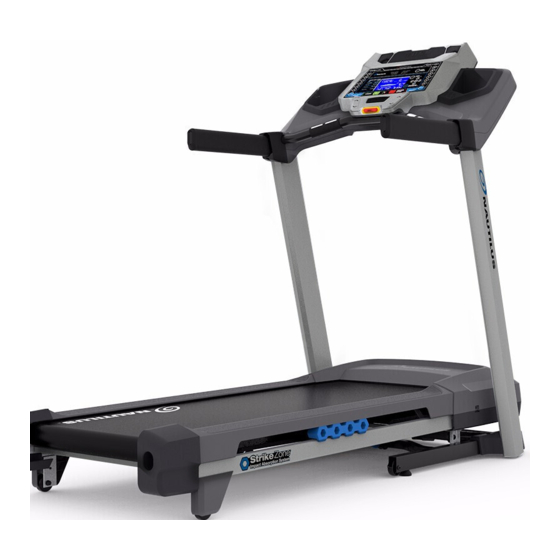
FEATURES Handlebar Motor Cover Ergo Bar Base Contact Heart Rate (CHR) Sensors Leveler Emergency Safety Key Port Transport Wheel Hydraulic Lift Console Dampener USB Port Side Foot Support Rails MP3 Input Walking Belt and Deck Media Tray Power Switch Speaker AC Inlet Storage Tray Telemetry Heart Rate (HR) Receiver (not shown) Upright Media Cable (not shown) -
Page 25: Console Features
Console Features The Console provides important information about your workout and lets you control the resistance levels while you exercise. The Console features touch control buttons to navigate you through the exercise programs. Goal Track Achievement Lights Pre-Set Pre-Set Speed Incline Buttons Buttons Incline Speed Enter Enter Button Button INCLINE SPEED Fan Button Console Display Goal Track Achievement Lights- when an achievement level is reached or a result is reviewed, the achievement indicator light will activate. - Page 26 Incline Enter button- Activates the incline motor to adjust the Walking Deck to the selected Pre-Set Incline value. START button- Begins a Quick Start workout, begins a Program Workout after customized for the User, or resumes a paused workout. FAN button- Controls 3-speed fan PAUSE / STOP button- Pauses an active workout, ends a paused workout, or exits to the previous menu Pre-Set Speed buttons- Selects a speed value for the Walking Belt.
- Page 27 Option Guides The Option Guides inform the User where they are in a list of options with the MORE and PREVIOUS Options. If the MORE Options (decrease arrow) is active, then there are additional options that can be viewed by pushing the Decrease () button. The MORE Options (decrease arrow) is active until the User reaches the end of the list. When the User is at the end of the options list, the MORE Options (decrease arrow) will deactivate and the Decrease () button will not provide further options. The PREVIOUS Options (increase arrow) is active as soon as the User begins moving through the list. Use the Increase () button to see the previous options. Active User Display The Active User Display shows which User Profile is currently selected. Time / Lap (Time) The TIME display field shows the total time count of the workout, the average Time for the User Profile, or the total opera- tional time of the machine.
- Page 28 USB Charging If a USB Device is attached to the USB Port, the Port will attempt to charge the Device. Note: Depending on the amperage of device, the power supplied from the USB Port may not be enough to operate the Device and charge it at the same time.
- Page 29 Remote Heart Rate Monitor Monitoring your Heart Rate is one of the best procedures to control the intensity of your exercise. Contact Heart Rate (CHR) sensors are installed to send your heart rate signals to the Console. The Console can also read telemetry HR sig- nals from a Heart Rate Chest Strap Transmitter that operates in the 4.5kHz - 5.5kHz range. Note: The heart rate chest strap must be an uncoded heart rate strap from Polar Electro or an uncoded POLAR com- ®...
- Page 30 Heart Rate Calculations Your maximum heart rate usually decreases from 220 Beats Per Minute (BPM) in childhood to approximately 160 BPM by age 60. This fall in heart rate is usually linear, decreasing by approximately one BPM for each year. There is no indication that training influences the decrease in maximum heart rate. Individuals of the same age could have different maximum heart rates. It is more accurate to find this value by completing a stress test than by using an age related formula. Your at-rest heart rate is influenced by endurance training. The typical adult has an at rest heart rate of approximately 72 BPM, whereas highly trained runners may have readings of 40 BPM or lower. The Heart Rate table is an estimate of what Heart Rate Zone (HRZ) is effective to burn fat and improve your cardiovas- cular system. Physical conditions vary, therefore your individual HRZ could be several beats higher or lower than what is shown.
-
Page 31: Operations
OPERATIONS What to Wear Wear rubber-soled athletic shoes. You will need the appropriate clothes for exercise that allow you to move freely. How Often Should You Exercise Consult a physician before you start an exercise program. Stop exercising if you feel pain or tightness in your chest, become short of breath, or feel faint. Contact your doctor before you use the machine again. Use the values calculated or measured by the machine’s computer for reference purposes only. -
Page 32: Power Up / Idle Mode
• If there is an emergency, pull out the Safety Key to shut off the power to the Belt and Incline Motors. This will quickly stop the belt (brace yourself- this is an abrupt stop) and clear the workout. Push the PAUSE/STOP button to stop the belt and pause the program. Push the USER button to select the desired User for the workout. 8. Select your workout using the PROGRAMS button and the Decrease/Increase buttons. -
Page 33: User Profiles
Push OK to set. The Console goes to the Power-Up Mode screen. Note: To adjust these selections, consult the “Console Set-Up Mode” section. Quick Start ( Manual ) Program The Quick Start ( Manual ) program lets you start a workout without entering any information. During a Manual Workout, each column represents a 2 minute time period. The active column will advance across the screen every 2 minutes. If the workout lasts for more than 32 minutes, the active column is fixed on the farthest column on the right and pushes the previous columns off the display. - Page 34 3. The Console display shows the EDIT prompt and the current User Profile name. Push OK to start the Edit User Profile option. T o exit the User Profile options, push the PAUSE/STOP button and the console will go back to the Power-Up Mode screen. 4. The Console display shows the NAME prompt and the current User Profile name. Note: The User name will be blank if this is the first edit.
-
Page 35: Profile Programs
The Upper Display shows the current value setting: “ON” or “OFF”. Push the Increase() or Decrease() buttons to change the value. The default is “ON”. Push the OK button to set the Telemetry Heart Rate Receiver to active. 10. The Console will go to the Power-Up Mode screen with the user selected. Reset a User Profile 1. - Page 36 QUICK GOAL Distance Time Default MAX SPEED : 3 mph Calories ICKSTART (press and hold to customize TRAIN/PACER: PERFORMANCE 1: COMPARE:AVERAGE is automatically selected by ogram) TRAIN this program, Console uses AVG pace from 1 MILE PACER yards previous workout if this distance has not been ICK GOAL 5K PACER previously done.
- Page 37 CALORIE BURN (SCH): Use Case 4: Programs and Their Brickyards Incline. Speed is preset. Default MAX SPEED : 1 mph TRAIN FAT BURN 2: FAT BURN 1: ENDURANCE PERFORMANCE Fast Burn – steady pace with high intensity Slow Burn – steady pace with low intensity HEART HEALTH: (moderate incline / moderate speed) (low incline / low speed)
- Page 38 8. U se the Increase() or Decrease() buttons to adjust the workout value, and push OK. 9. The Console will display the “READY ?” prompt. 10. Push START to begin the goal-oriented workout. The workout will begin after a three second, audible countdown. Note: The Console will display “RAMPING UP”...
-
Page 39: Pausing Or Stopping
The RECOVERY TEST program uses your age and other User information to see how your heart rate adjusts from a selected heart rate zone to a casual pace. The program supplies a score that can be used to track how your heart adjusts to physical conditions. - Page 40 Note: To exit the Goal Track mode, push the Goal Track button and the console will go back to the Power-Up Mode screen. 3. The Console will display the “LONGEST WORKOUT”, the workout values and activate the corresponding Achievement light. After 4 seconds, the Console will display the name of the workout, and then the date it was performed (except for “LAST 7 DAYS” and “LAST 30 DAYS”). Note: To exit the GOAL TRACK statistics, push the PAUSE/STOP button and the console will go back to the Power-Up Mode screen. 4. Push the Decrease() button to move to the next GOAL TRACK statistic, “CALORIE RECORD”. The Console will display the workout results with the most Calories value. The Console will cycle between the workout results, the name of the workout profile, and the date of the workout every 4 seconds. Use the Left() or Right() buttons to force the cycle between the workout results.
-
Page 41: Console Setup Mode
CONSOLE SETUP MODE The Console Setup Mode lets you control the sound settings ( on/off ), adjust the date and time, or see maintenance statistics (Total Run Hours and Software Version– for service technician use only). Hold down the PAUSE/STOP button and Right button together for 3 seconds while in the Power-Up Mode to go into the Console Setup Mode. Note: Push PAUSE/STOP to exit the Console Setup Mode and return to the Power-Up Mode screen. The Console display shows the Date prompt with the current setting. To change, push the Increase/Decrease buttons to adjust the currently active value (flashing). Push the Left/Right buttons to change which segment is the currently active value (month / day / year). -
Page 42: Maintenance
Do not remove the Motor Control Board (MCB) Cover. Dangerous voltages and moving parts are present. The components are serviceable only by approved service personnel or by following service procedures supplied by Nautilus, Inc. Note: Do not use petroleum based products. -
Page 43: Adjusting The Belt Tension
Adjusting the Belt Tension If the walking belt starts to slip during use, it is necessary to adjust the tension. Your treadmill has tension bolts at the rear the treadmill. Before you adjust the belt tension, start the treadmill by pushing the START button. Be sure not to touch the walking belt or step on the power cord. -
Page 44: Lubricating The Walking Belt
4. M onitor the path of the belt for approximately 2 minutes. Continue to adjust the bolts until the walking belt is centered. Push PAUSE/STOP twice to stop the walking belt and end the Quick Start workout. Lubricating the Walking Belt Your treadmill is equipped with a low maintenance deck and belt system. The Walking Belt is pre-lubricated. Belt friction can affect the function and life of the machine. - Page 45 Store silicone lubricant in a safe place. Keep out of reach of children. Silicone lubricant is not intended for human consumption. Manually rotate the belt 1/2 of the length of the belt and apply lubricant again. Unfold the machine. Refer to the “Unfolding the Machine” procedure in this manual. Keep clear of the movement path of the walking deck.
-
Page 46: Maintenance Parts
Maintenance Parts Console Assembly Tray, Right Handlebar Shroud, Right Safety Key Port Right Upright Cable Upright, Left Upright, Right Base Shroud, Left Contact Heart Rate Sensor Base Shroud, Right Handlebar Shroud, Left Console Cable Base Cable Power Cord Tray, Left Base Assembly... - Page 47 Maintenance Parts ( Frame ) Front Back Fuse Base Support Incline Adjuster Power Switch Deck Cushioners Pivot Assembly Power Input Transport Wheel Belt Tensioner Motor Cover Leveler Rear Roller Cover Side Foot Support Rails Lifting Cylinder GG Motor Control Board (MCB) Cover...
-
Page 48: Troubleshooting
TROUBLESHOOTING Condition/Problem Things to Check Solution No display/partial display/ Check electrical (wall) Make sure unit is plugged into a functioning wall outlet. Test the unit will not turn on outlet outlet with a known functioning device such as a lamp. Check connection at front Connection should be secure and undamaged. - Page 49 Condition/Problem Things to Check Solution Console shuts off (enters Check electrical (wall) Make sure unit is plugged into a functioning wall outlet. Test the sleep mode) while in use outlet outlet with a known functioning device such as a lamp. Check connection at front Connection should be secure and undamaged. Replace of unit adapter or connection at unit if either are damaged.
- Page 50 ™ ™ Nautilus Bowflex Schwinn Universal ™ ™ ™ ™ 8004420.121518.C...