Table of Contents
Advertisement
Advertisement
Table of Contents

Related Manuals for Asus Z97-AR


Summary of Contents for Asus Z97-AR
- Page 1 Z97-AR...
- Page 2 Product warranty or service will not be extended if: (1) the product is repaired, modified or altered, unless such repair, modification of alteration is authorized in writing by ASUS; or (2) the serial number of the product is defaced or missing.
-
Page 3: Table Of Contents
Contents Safety information ...................... iv About this guide ......................iv Package contents ....................... vi Z97-AR specifications summary ................vi Chapter 1: Product Introduction Before you proceed ................... 1-1 Motherboard overview ................1-1 Central Processing Unit (CPU) ..............1-4 System memory ..................1-7 Expansion slots .................. -
Page 4: Safety Information
Safety information Electrical safety • To prevent electrical shock hazard, disconnect the power cable from the electrical outlet before relocating the system. • When adding or removing devices to or from the system, ensure that the power cables for the devices are unplugged before the signal cables are connected. If possible, disconnect all power cables from the existing system before you add a device. - Page 5 Refer to the following sources for additional information and for product and software updates. ASUS websites The ASUS website provides updated information on ASUS hardware and software products. Refer to the ASUS contact information. Optional documentation Your product package may include optional documentation, such as warranty flyers, that may have been added by your dealer.
-
Page 6: Package Contents
Package contents Check your motherboard package for the following items: ASUS Z97-AR Motherboard Motherboard Cables 2 x Serial ATA 6.0 Gb/s cables 1 x ASUS SLI bridge connector Accessories 2-in-1 Q-connector Support DVD Application DVD User Guide Documentation If any of the above items is damaged or missing, contact your retailer. - Page 7 - Supports jack-detection, multi-streaming and front panel jack-retasking (MIC) - Optical S/PDIF out port at rear I/O Intel Z97 Express Chipset - supports ASUS USB 3.0 Boost ® - 6 x USB 3.0 / 2.0 ports (2 ports at mid-board, 4 ports at rear panel [blue]) - 8 x USB 2.0 / 1.1 ports (6 ports at mid-board, 2 ports at rear panel)
- Page 8 Z97-AR specifications summary DIGI+ Power Control - CPU Power - Industry-leading digital 8-phase power design - ASUS CPU power utility - Auto Tuning, TPU, GPU Boost, 2-level TPU switch - EPU, EPU switch Fan Xpert 3 - Featuring Fan Auto Tuning function and multiple thermistors selection for...
- Page 9 - O.C. Tuner Features - CrashFree BIOS 3 - EZ Flash 2 ASUS Q-Design - ASUS Q-LED (CPU, DRAM, VGA, Boot Device LED) - ASUS Q-Slot - ASUS Q-DIMM - ASUS Q-Connector 5X Protection featuring all-round protection provides the best quality, reliability, and durability USB 3.0 Boost...
- Page 10 Front panel audio connector (AAFP) 64 Mb Flash ROM, UEFI AMI BIOS, PnP, DMI 2.7, WfM 2.0, SM BIOS 2.7, ACPI 5.0, Multi-language BIOS, ASUS EZ Flash 2, ASUS CrashFree BIOS 3, My BIOS features Favorites, Quick Note, Last Modified log, F12 PrintScreen, F3 Shortcut function, and ASUS DRAM SPD (Serial Presence Detect) memory information WfM 2.0, DMI 2.7, WOL by PME, PXE...
-
Page 11: Chapter 1: Product Introduction
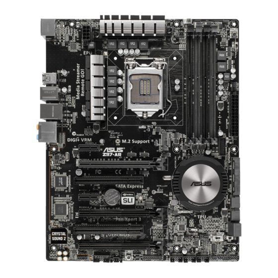
1.2.2 Screw holes Place six screws into the holes indicated by circles to secure the motherboard to the chassis. Do not overtighten the screws! Doing so can damage the motherboard. ASUS Z97-AR... - Page 12 Place this side towards the rear of the chassis 1.2.3 Motherboard layout Chapter 1: Product introduction...
- Page 13 TPM connector (20-1 pin TPM) 1-32 Power-on button 1-41 Thunderbolt header (5-pin TB_HEADER) 1-35 Serial port connector (10-1 pin COM) 1-27 Front panel audio connector (10-1 pin AAFP) 1-30 Digital audio connector (4-1 pin SPDIF_OUT) 1-30 M.2 Socket 3 1-31 ASUS Z97-AR...
-
Page 14: Central Processing Unit (Cpu)
Contact your retailer immediately if the PnP cap is missing, or if you see any damage to the PnP cap/socket contacts/motherboard components. ASUS will shoulder the cost of repair only if the damage is shipment/ transit-related. - Page 15 1.3.1 Installing the CPU ASUS Z97-AR...
- Page 16 1.3.2 CPU heatsink and fan assembly installation Apply the Thermal Interface Material to the CPU heatsink and CPU before you install the heatsink and fan, if necessary. To install the CPU heatsink and fan assembly Chapter 1: Product introduction...
-
Page 17: System Memory
(DIMM) sockets. A DDR3 module is notched differently from a DDR or DDR2 module. DO NOT install a DDR or DDR2 memory module to the DDR3 slot. According to Intel CPU spec, DIMM voltage below 1.65 V is recommended to protect the ® CPU. ASUS Z97-AR... - Page 18 The stability and compatibility of the memory modules depend on the CPU’s capabilities and other installed devices. • For system stability, use a more efficient memory cooling system to support a full memory load (4 DIMMs). • Visit the ASUS website at: www.asus.com for the latest QVL. Chapter 1: Product introduction...
- Page 19 Z97-AR Motherboard Qualified Vendors Lists (QVL) DDR3 3200 (O.C.) MHz capability Vendors Part No. Size SS/DS Chip Chip Timing Voltage DIMM socket Brand support (Optional) AVEXIR AVD3UH32001304G-4CI(XMP) 16GB (4x4GB) 13-15-15-35 1.65V • • • G.SKILL F3-3200C12Q-16GTXDG(XMP) 16GB (4x4GB) 12-15-15-35 1.65V •...
- Page 20 DDR3 2800 (O.C.) MHz capability Vendors Part No. Size SS/DS Chip Chip Timing Voltage DIMM socket Brand support (Optional) AVEXIR AVD3UH28001208G- 32GB (4x8GB) 12-14-14-35 1.65V • • • 4BZ1(XMP) A_DATA AX3U2800W 16GB (4x4GB) 12-14-14-36 1.65V • • • 4G12(XMP) A_DATA AX3U2800W 32GB (4x8GB) 12-14-14-36...
- Page 21 1.65 • • • 64GBZHD(XMP) G.SKILL F3-19200CL10Q- 32GB (4x8GB) 10-12-12-31 1.65 • • 32GBZHD(XMP) G.SKILL F3-19200CL11Q- 16GB (4x4GB) 11-11-11-31 1.65 • • • 16GBZHD(XMP) G.SKILL F3-19200CL9D-4GBPIS(XMP) 4G (2x2GB) 9-11-9-28 1.65 • • (continued on the next page) ASUS Z97-AR 1-11...
- Page 22 DDR3 2400 (O.C.) MHz capability Vendors Part No. Size SS/DS Chip Chip Timing Voltage DIMM socket Brand support (Optional) G.SKILL F3-19200CL9Q- 16GB (4x4GB) 9-11-11-31 1.65 • • • 16GBZMD(XMP) G.SKILL F3-2400C11Q-32GXM(XMP) 32GB (4x8GB) 11-13-13-31 1.65 • • • GEIL GOC316GB24 16GB (4x4GB) 10-11-11-30 1.65...
- Page 23 CMD32GX3M4A1866C9 32GB (4x8GB) 9-10-9-27 • • • (Ver3.24)(XMP) CORSAIR CMD8GX3M2A1866C9 8GB (2x4GB) • • • (Ver4.13)(XMP) CORSAIR CMD8GX3M2A1866C9 8GB (2x4GB) 9-10-9-27 • • (Ver5.12)(XMP) CORSAIR CMD8GX3M2A1866C9 8GB (2x4GB) 9-10-9-27 • • (Ver8.16)(XMP) (continued on the next page) ASUS Z97-AR 1-13...
- Page 24 DDR3 1866 (O.C.) MHz capability Vendors Part No. Size SS/DS Chip Chip Timing Voltage DIMM socket Brand support (Optional) CORSAIR CMT32GX3M4X1866C9(Ver3.23) 32GB 9-10-9-27 • • • (XMP) (4x8GB) CORSAIR CMY16GX3M2A1866C9 (Ver 16GB 9-10-9-27 • • • 4.21)(XMP) (2x8GB) CORSAIR CMY8GX3M2A1866C9 (Ver3.24) 9-10-9-27 •...
- Page 25 600C10 (Ver2.21) (2x8GB) (XMP) CORSAIR CML8GX3M2A16 9-9-9- 24 • • • 00C9 (Ver7.12) (2x4GB) (XMP) CORSAIR CMV8GX3M1A1 11-11-11-30 • • • 600C11 CORSAIR CMX8GX3M2 9-9-9-24 1.65 • • • A1600C9 (Ver3.19) (2x4GB) (XMP) (continued on the next page) ASUS Z97-AR 1-15...
- Page 26 DDR3 1600 MHz capability Vendors Part No. Size SS/DS Chip Chip NO. Timing Voltage DIMM socket Brand support (Optional) CORSAIR CMZ16GX3M2A1 16GB 10-10- • • • 600C10 (Ver.3.24) (2x8GB) 10-27 (XMP ) CORSAIR CMZ16GX3M 16GB 9-9-9-24 • • • 4A1600C9(XMP) (4x4GB) CORSAIR CMZ16GX3M4X1600C9...
- Page 27 846B Transcend TS1GLK64W6H SAMSUNG K4B4G08 11-11-11-28-1 • • • Transcend TS512MLK64W6H SAMSUNG K4B4G08 11-11-11-28-2 • • • UMAX 84E44G93UM- UMAX U2S96D3 1600-11-11-11-28 • • • 16BPSYW 0TP-16 UMAX 84E48G93UM- UMAX U2S96D3 1600-11-11-11-28 • • • 16BPSYW 0TP-16 ASUS Z97-AR 1-17...
- Page 28 DDR3 1333 MHz capability Vendors Part No. Size SS/DS Chip Brand Chip NO. Timing Voltage DIMM socket support (Optional) AE32G1339U1-U 23EY4587 • • • MB3H AE34G1339U2-U 23EY4587 • • • MB3H Apacer 78.B1GDE.9L10C Apacer AM5D5908 • • • CEHSBG Asint SLA302G08-EDJ1C ASint 302G08-DJ1C...
- Page 29 20YT3NG 9-9-9-24 • • • Silicon Power SP004GBLTU133V02 S-POWER 20YT3NG 9-9-9-24 • • • UMAX 84E44G93UM-13BPSYW UMAX U2S96D3 1333-9- • • • 0TP-13 9-9-24 UMAX 84E48G93UM-13BPSYW UMAX U2S96D3 1333-9- • • • 0TP-13 9-9-24 1.4.3 DIMM installation ASUS Z97-AR 1-19...
-
Page 30: Expansion Slots
To remove a DIMM Expansion slots In the future, you may need to install expansion cards. The following sub-sections describe the slots and the expansion cards that they support. Unplug the power cord before adding or removing expansion cards. Failure to do so may cause you physical injury and damage motherboard components. - Page 31 This motherboard supports PCI Express x16 network cards, SCSI cards, and other cards that comply with the PCI Express specifications. Slot No. Expansion slot PCIe 2.0 x1_1 slot PCIe 3.0/2.0 x16_1 slot PCI_1 slot PCIe 2.0 x1_2 slot PCIe 3.0/2.0 x16_2 slot PCI_2 slot PCIe 2.0 x16_3 slot ASUS Z97-AR 1-21...
- Page 32 PCI Express 3.0 operating mode VGA configuration PCIe 3.0/2.0 x16_1 PCIe 3.0/2.0 x16_2 x16 (single VGA Single VGA/PCIe card recommended) Dual VGA/PCIe card • We recommend that you provide sufficient power when running CrossFireX™ or SLI™ mode. • Connect a chassis fan to the motherboard connector labeled CHA_FAN1-4 when using multiple graphics cards for better thermal environment.
-
Page 33: Jumpers
• Due to chipset behavior, AC power off is required to enable C.P.R. function. You must turn off and on the power supply or unplug and plug the power cord before rebooting the system. ASUS Z97-AR 1-23... - Page 34 CPU Over Voltage jumper (3-pin CPU_OV) The CPU Over Voltage jumper allows you to set a higher CPU voltage for a flexible overclocking system, depending on the type of the installed CPU. To gain more CPU voltage setting, insert the jumper to pins 2-3. To go back to its default CPU voltage setting, insert the jumper to pins 1-2.
-
Page 35: Connectors
USB 3.0 ports 34 PS/2 keyboard/mouse port Optical S/PDIF Out port LAN port* Audio I/O ports** HDMI port * and **: Refer to the tables on the next page for LAN port LEDs and audio port definitions. ASUS Z97-AR 1-25... - Page 36 • The plugged USB 3.0 device may run on xHCI or EHCI mode, depending on the operating system’s setting. • USB 3.0 devices can only be used for data storage. • We strongly recommend that you connect USB 3.0 devices to USB 3.0 ports for faster and better performance from your USB 3.0 devices.
- Page 37 This connector connects to Serial ATA 6.0 Gb/s hard disk drives via Serial ATA 6.0 Gb/s signal cables. When using hot-plug and NCQ, set the SATA Mode Selection item in the BIOS to [AHCI]. See section 2.6.3 PCH Storage Configuration for details. ASUS Z97-AR 1-27...
- Page 38 Ensure that the CPU fan cable is securely installed to the CPU fan connector. • The CPU_FAN connector supports the CPU fan of maximum 1A (12 W) fan power. • The CPU_FAN connector and CHA_FAN connectors support the ASUS FAN Xpert 3 feature. 1-28 Chapter 1: Product introduction...
- Page 39 The system may become unstable or may not boot up if the power is inadequate. • If you want to use two or more high-end PCI Express x16 cards, use a PSU with 1000W power or above to ensure the system stability. ASUS Z97-AR 1-29...
- Page 40 Front panel audio connector (10-1 pin AAFP) This connector is for a chassis-mounted front panel audio I/O module that supports either HD Audio or legacy AC`97 audio standard. Connect one end of the front panel audio I/O module cable to this connector. •...
- Page 41 Refer to the technical documentation that came with the chassis for details. M.2 socket 3 This socket allows you to install an M.2 (NGFF) SSD module. • This socket supports M Key and type 2260/2280 storage devices. • The M.2 (NGFF) SSD module is purchased separately. ASUS Z97-AR 1-31...
- Page 42 USB 2.0 connectors (10-1 pin USB910, USB1112, USB1314) These connectors are for USB 2.0 ports. Connect the USB module cable to any of these connectors, then install the module to a slot opening at the back of the system chassis. These USB connectors comply with USB 2.0 specifications and supports up to 480 Mb/s connection speed.
- Page 43 Pressing the power switch for more than four seconds while the system is ON turns the system OFF. • Reset button (2-pin RESET) This 2-pin connector is for the chassis-mounted reset button for system reboot without turning off the system power. ASUS Z97-AR 1-33...
- Page 44 USB 3.0 connector (20-1 pin USB3_12) This connector allows you to connect a USB 3.0 module for additional USB 3.0 front or rear panel ports. With an installed USB 3.0 module, you can enjoy all the benefits of USB 3.0 including faster data transfer speeds of up to 5 Gb/s, faster charging time for USB-chargeable devices, optimized power efficiency, and backward compatibility with USB 2.0.
- Page 45 The add-on Thunderbolt I/O card and Thunderbolt cables are purchased separately. T_Sensor connector (2-pin T_SENSOR1) This connector is for the thermistor cable that allows you to monitor the temperature of your motherboard’s critical components and connected devices. The thermistor cable is purchased separately. ASUS Z97-AR 1-35...
-
Page 46: Onboard Leds
Onboard LEDs Standby Power LED The motherboard comes with a standby power LED that lights up to indicate that the system is ON, in sleep mode, or in soft-off mode. This is a reminder that you should shut down the system and unplug the power cable before removing or plugging any motherboard components. - Page 47 TPU LED (TPU_LED) The TPU LED lights up when the TPU switch is enabled. EPU LED (OLED2) The EPU LED lights up when the EPU switch is enabled. ASUS Z97-AR 1-37...
-
Page 48: Onboard Buttons And Switches
Onboard buttons and switches Onboard buttons and switches allow you to fine-tune performance when working on a bare or open-case system. This is ideal for overclockers and gamers who continually change settings to enhance system performance. EPU switch Enable this switch to automatically detect the current PC loadings and intelligently moderate the power consumption. - Page 49 BIOS default settings. A message will appear during POST reminding you that the BIOS has been restored to its default settings. • We recommend that you download and update to the latest BIOS version from www.asus.com after using the MemOK! function. ASUS Z97-AR 1-39...
- Page 50 TPU switch With its two-level adjustment functions, the TPU allows you to automatically adjusts the CPU ratio and clock speed for an optimal system performance. • Enable this switch when the system is powered off. • When the TPU switch is set to Enabled (TPU_I: CPU Ratio Boost), the system automatically adjusts the CPU ratio for an enhanced performance.
- Page 51 EZ XMP switch Enable this switch to overclock the installed DIMMs, allowing you to enhance the DIMM’s speed and performance. ASUS Z97-AR 1-41...
-
Page 52: Software Support
Place the Support DVD into the optical drive. If Autorun is enabled in your computer, the DVD automatically displays the lists of the unique features of your ASUS motherboard. Click the Drivers, Utilities, AHCI/RAID Driver, Manual, Contact, or Specials tabs to display their respective menus. -
Page 53: Chapter 2: Bios Information
DVD and a USB flash disk drive. Save a copy of the original motherboard BIOS file to a USB flash disk in case you need to restore the BIOS in the future. Copy the original motherboard BIOS using the ASUS Update utility. - Page 54 Service Provider). 2.1.2 ASUS EZ Flash 2 The ASUS EZ Flash 2 feature allows you to update the BIOS without using an OS-based utility. Before you start using this utility, download the latest BIOS file from the ASUS website at http://www.asus.com.
- Page 55 2.1.3 ASUS CrashFree BIOS 3 utility The ASUS CrashFree BIOS 3 is an auto recovery tool that allows you to restore the BIOS file when it fails or gets corrupted during the updating process. You can restore a corrupted BIOS file using the motherboard support DVD or a USB flash drive that contains the updated BIOS file.
- Page 56 BIOS file to the USB port. The utility automatically checks the devices for the BIOS file. When found, the utility reads the BIOS file and automatically enters ASUS EZ Flash 2 utility. The system requires you to enter BIOS Setup to recover BIOS settings.
- Page 57 (optical drive) to Drive D (USB flash drive). Welcome to FreeDOS (http://www.freedos.org)! C:/> d: D:/> Updating the BIOS file To update the BIOS file: On the FreeDOS prompt, type bupdater /pc /g and press <Enter>. D:/> bupdater /pc /g ASUS Z97-AR...
- Page 58 On the BIOS Updater screen, press <Tab> to switch from Files panel to Drives panel then select D:. ASUSTeK BIOS Updater for DOS V1.30 [2014/01/01] Current ROM Update ROM BOARD: Z97-A BOARD: Unknown VER: 0210 (H :00 B :00) VER: Unknown DATE: 02/12/2014...
-
Page 59: Bios Setup Program
The BIOS setup screens shown in this section are for reference only. Some screen displays may not be the same as what you see on your screen. • Visit the ASUS website at www.asus.com to download the latest BIOS file for this motherboard. •... - Page 60 2.2.1 EZ Mode By default, the EZ Mode screen appears when you enter the BIOS setup program. The EZ Mode provides you an overview of the basic system information, and allows you to select the display language, system performance mode and boot device priority. To access the Advanced Mode, click Exit/Advanced Mode, then select Advanced Mode or press <F7>...
- Page 61 Hot Keys Language Q-Fan control EZ Tuning Wizard Quick Note Menu bar Last modified settings Sub-menu item General help Configuration fields Scroll bar Menu items Goes back to EZ Mode Displays the CPU/motherboard temperature, CPU and memory voltage output ASUS Z97-AR...
- Page 62 Menu bar The menu bar on top of the screen has the following main items: For saving the frequently-used system settings and configuration My Favorites For changing the basic system configuration Main For changing the overclocking settings Ai Tweaker For changing the advanced system settings Advanced For displaying the system temperature, power status, and changing the Monitor...
- Page 63 A configurable field is highlighted when selected. To change the value of a field, select it and press <Enter> to display a list of options. Last Modified button This button shows the items that you last modified and saved in BIOS Setup. ASUS Z97-AR 2-11...
- Page 64 2.2.3 QFan Control The QFan Control allows you to set a fan profile or manually configure the operating speed of your CPU and chassis fans. Click to select a fan to be Click to activate Click to activate DC Mode configured PWM Mode Click to apply the fan setting...
- Page 65 Select the CPU fan type (Box cooler, Tower cooler, or Water cooler) that you installed then click Next. If you are not sure of the CPU fan type, click I’m not sure. The system automatically detects the CPU fan type. Click Next then click Yes to confirm auto-tuning. ASUS Z97-AR 2-13...
- Page 66 Creating RAID To create RAID: Press <F11> on your keyboard or click from the BIOS screen to open EZ Tuning Wizard screen. Click RAID then click Next. • Ensure that your HDDs have no existing RAID volumes. • Ensure to connect your HDDs to Intel SATA connectors.
-
Page 67: My Favorites
Press <F3> on your keyboard or click from the BIOS screen to open Setup Tree Map screen. On the Setup Tree Map screen, select the BIOS items that you want to save in MyFavorites screen. Main menu panel Selected shortcut items Submenu panel ASUS Z97-AR 2-15... -
Page 68: Main Menu
Select an item from main menu panel, then click the submenu that you want to save as favorite from the submenu panel and click You cannot add the following items to My Favorite items: • Items with submenu options • User-managed items such as language and boot order •... - Page 69 To clear the user password, follow the same steps as in changing a user password, but press <Enter> when prompted to create/confirm the password. After you clear the password, the User Password item on top of the screen shows Not Installed. ASUS Z97-AR 2-17...
-
Page 70: Ai Tweaker Menu
Ai Tweaker menu The Ai Tweaker menu items allow you to configure overclocking-related items. Be cautious when changing the settings of the Ai Tweaker menu items. Incorrect field values can cause the system to malfunction. The configuration options for this section vary depending on the CPU and DIMM model you installed on the motherboard. - Page 71 2.5.2 ASUS MultiCore Enhancement [Auto] [Auto] This item allows you to maximize the oveclocking performance optimized by ASUS core ratio settings. [Disabled] This item allows you to set to default core ratio settings. 2.5.3 CPU Core Ratio [Sync All Cores] This item allows you to set the CPU core ratio limit per core or synchronize automatically to all cores.
- Page 72 2-Core Ratio Limit [Auto] Select [Auto] to apply the CPU default Turbo Ratio setting or manually assign a 2-Core Limit value that must be higher than or equal to the 3-Core Ratio Limit. If you assign a value for 2-Core Ratio Limit, do not set the 1-Core Ratio Limit to [Auto]. 3-Core Ratio Limit [Auto] Select [Auto] to apply the CPU default Turbo Ratio setting or manually assign a 3-Core Limit value that must be higher than or equal to the 4-Core...
- Page 73 [Keep Current Settings]. 2.5.12 EPU Power Saving Mode [Disabled] The ASUS EPU (Energy Processing Unit) sets the CPU in its minimum power consumption settings. Enable this item to set lower CPU VCCIN and Vcore voltages and achieve the best energy saving condition.
- Page 74 DRAM RAS# to CAS# Delay [Auto] Configuration options: [Auto] [1] – [31] DRAM RAS# PRE Time [Auto] Configuration options: [Auto] [1] – [31] DRAM RAS# ACT Time [Auto] Configuration options: [Auto] [1] – [63] DRAM Command Rate [Auto] Configuration options: [Auto] [1] – [2] Secondary Timings DRAM RAS# to RAS# Delay [Auto] Configuration options: [Auto] [1] –...
- Page 75 DRAM IO-L (CHB_R0D1) [Auto] Configuration options: [Auto] [1] - [15] DRAM IO-L (CHB_R1D0) [Auto] Configuration options: [Auto] [1] - [15] DRAM IO-L (CHB_R1D1) [Auto] Configuration options: [Auto] [1] - [15] Third Timings tRDRD [Auto] Configuration options: [Auto] [1] - [7] ASUS Z97-AR 2-23...
- Page 76 tRDRD_dr [Auto] Configuration options: [Auto] [1] - [15] tRDRD_dd [Auto] Configuration options: [Auto] [1] - [15] tWRRD [Auto] Configuration options: [Auto] [1] - [63] tWRRD_dr [Auto] Configuration options: [Auto] [1] - [15] tWRRD_dd [Auto] Configuration options: [Auto] [1] - [15] tWRWR [Auto] Configuration options: [Auto] [1] - [7] tWRWR_dr [Auto]...
- Page 77 Scrambler Setting [Optimized (ASUS)] This item allows you to set the optimized mode to enhance system stability. Configuration options: [Optimized (ASUS] [Default (MRC)] MCH Full Check [Auto] Enable this item to enhance the stability of your system. Disable this item to enhance the DRAM overclocking capability.
- Page 78 CPU VRM Switching Frequency [Auto] This item affects the VRM transient response speed and the component thermal production. Select [Manual] to configure a higher frequency for a quicker transient response speed. Configuration options: [Auto] [Manual] DO NOT remove the thermal module. The thermal conditions should be monitored. The following item appears only when you set the CPU VRM Switching Frequency to [Manual].
- Page 79 Decrease the switching frequency to reduce the power consumption or increase the switching frequency to enhance voltage stability. When this item is set to [+] or [-], the Frequency Tuning Offset appears that allows you to set its value from 0% to 6%. ASUS Z97-AR 2-27...
- Page 80 CPU Internal Power Fault Control Thermal Feedback [Auto] This item allows your system to take precautionary actions to protect the CPU when the thermal condition of the external regulator exceeds the threshold. Configuration options: [Auto] [Disabled] [Enabled] CPU Integrated VR Fault Management [Auto] Disable this item to prevent tripping the Fully Integrated Voltage Regulator when doing over-voltage.
- Page 81 CPU Core Voltage Override [Auto] This item allows you to set the CPU Core Voltage override. Use the <+> or <-> keys to adjust the value, The values range from 0.001V to 1.920 V with a 0.001 V interval. ASUS Z97-AR 2-29...
- Page 82 The following items appear only when you set the CPU Core Voltage to [Offset Mode]. Offset Mode Sign [+] To offset the voltage by a positive value. [–] To offset the voltage by a negative value. CPU Core Voltage Offset Use the <+>...
- Page 83 You can use the <+> or <-> keys to adjust the value. The values range from 0.001 V to 0.999 V with a 0.001 V interval. 2.5.20 CPU Analog I/O Voltage Offset Mode Sign [+] To offset the voltage by a positive value. [–] To offset the voltage by a negative value. ASUS Z97-AR 2-31...
- Page 84 CPU Analog I/O Voltage Offset [Auto] This item allows you to set the amount of voltage fed to the analog portion of the I/O on the CPU. By default, this item takes the standard value of the installed CPU. Increase the amount of voltage to enhance the overclocking capability.
- Page 85 BCLK DN is equal to the falling edge of the BCLK D+. You can use the <+> or <-> keys to adjust the value. The values range from 0.1 V to 1.9 V with a 0.00625 V interval. ASUS Z97-AR 2-33...
-
Page 86: Advanced Menu
2.5.31 Clock Crossing Reset Voltage [Auto] This item allows you to increase the value of the clock crossing reset voltage when the rising edge of the BCLK DN is equal to the falling edge of the BCLK D+. You can use the <+> or <->... - Page 87 This item allows you to select the CPU performance state during system boot before the operating system takes control. The CPU runs at a selected performance ratio based on CPU configuration. Configuration options: [Max Non-Turbo Performance] [Max Battery] [Turbo Performance] ASUS Z97-AR 2-35...
- Page 88 Dynamic Storage Accelerator [Disabled] This item allows you to accelerate the performance of the SSDs (Solid-State Drives) by dynamically adjusting the power management during heavy multitasking. Configuration options: [Enabled] [Disabled] CPU Power Management Configuration This item allows you to manage and configure the CPU’s power. Enhanced Intel SpeedStep Technology [Enabled] This item allows your system to adjust the CPU’s voltage and cores frequency, resulting in decreased power consumption and heat production.
- Page 89 Active Page Threshold size. When set to zero (0), it will go to Auto mode and checks if the partition size is enough at S3 entry. Ensure that the caching partition size is larger than the total memory size. ASUS Z97-AR 2-37...
- Page 90 Hybrid Hard Disk Support [Disabled] This item allows you to enable or disable the hybrid hard disk support for a faster resume time. Configuration options: [Enabled] [Disabled] Intel Smart Connect Technology This item allows the system to support Intel Smart Connect Technology, that periodically refreshes selected applications when the system is in sleep mode.
- Page 91 Configuration options: [Auto] [Disabled] [Enabled CPU Graphics Multi-Monitor [Disabled] This item allows you to empower both integrated and discrete graphics devices for the multi-monitor output. The CPU graphics shared system memory size is fixed at 64 MB. Configuration options: [Disabled] [Enabled] ASUS Z97-AR 2-39...
- Page 92 DMI Configuration This item allows you to control various DMI (direct media interface) to run at PCI-E 2.0 speed. DMI Gen 2 [Auto] Set this item to [Enabled] to run DMI at PCI-E 2.0 speed. Configuration options: [Enabled] [Disabled] NB PCI-E Configuration This item allows you to configure the NB PCI Express settings.
- Page 93 PCH - PCI Express options DMI Link ASPM Control [Disabled] This item allows you to control the Active State Power Management on both NB (NorthBridge) side and SB (SouthBridge) side of the DMI Link. Configuration options: [Disabled] [Enabled] ASUS Z97-AR 2-41...
- Page 94 ASPM to take effect. Configuration options: [Disabled] [L0s] [L1] [L0sL1] PEG ASPM Support [Disabled] This item allows you to select the ASPM state for energy-saving conditions, or use the ASUS optimized energy saving profile. Configuration options: [Disabled] [L0s] [L1] [L0sL1] [Auto] 2.6.7...
- Page 95 This item allows you to enable or disable the Wake-on-LAN function of the onboard LAN controller or other installed PCI-E LAN cards. Configuration options: [Disabled] [Enabled] Power On By Ring [Disabled] This item allows you to enable or disable the Wake-on-Modem function. Configuration options: [Disabled] [Enabled] ASUS Z97-AR 2-43...
- Page 96 Power On By RTC [Disabled] This item allows you to enable or disable the RTC (Real-Time Clock) to generate a wake event and configure the RTC alarm date. When enabled, you can set the days, hours, minutes, or seconds to schedule an RTC alarm date. Configuration options: [Disabled] [Enabled] 2.6.9 Network Stack Configuration...
-
Page 97: Monitor Menu
The onboard hardware monitor automatically detects and displays the CPU, chassis, and power fan speed in rotations per minute (RPM). If the fan is not connected to the motherboard, the field shows N/A. Select [Ignore] if you do not wish to display the detected speed. ASUS Z97-AR 2-45... - Page 98 2.7.4 CPU Core 0/3 Voltage, 3.3V Voltage, 5V Voltage, 12V Voltage The onboard hardware monitor automatically detects the voltage output through the onboard voltage regulators. Select [Ignore] if you do not want to detect this item. 2.7.5 CPU Q-Fan Control [Auto] This item allows you to set the CPU Q-Fan operating mode.
- Page 99 The following items appear only when you set the Chassis Fan Profile to [Manual]. Chassis Fan 1/4 Upper Temperature [70] Use the <+> or <-> keys to adjust the upper limit of the CPU temperature. The values range from 40°C to 90°C. ASUS Z97-AR 2-47...
- Page 100 Chassis Fan 1/4 Max. Duty Cycle(%) [100] Use the <+> or <-> keys to adjust the maximum chassis fan duty cycle. The values range from 20% to 100%. When the chassis temperature reaches the upper limit, the chassis fan will operate at the maximum duty cycle. Chassis Fan 1/4 Middle Temperature [45] Use the <+>...
-
Page 101: Boot Menu
POST time. [Full Initialization] All USB devices will be available during POST. This process will extend the POST time. [Partial For a faster POST time, only USB ports with keyboard and Initialization] mouse connections will be detected. ASUS Z97-AR 2-49... - Page 102 PS/2 Keyboard and Mouse Support [Auto] Select any of these settings when PS/2 keyboard and mouse are installed. These settings only apply when fastboot is enabled. [Auto] For a faster POST time, PS/2 devices are only available when the system boots up or rebooted when the PS/2 devices are not reconnected or changed.
- Page 103 Option ROM Messages [Enabled] [Enabled] The third-party ROM messages will be displayed during POST. [Disabled] Disables the ROM messages and displays only the ASUS logo during POST. 2.8.7 Interrupt 19 Capture [Disabled] This item allows you to trap Interrupt 19 by the option ROMs.
- Page 104 The following items appear only when you set the Launch CSM to [Enabled]. Boot Devices Control [UEFI and Legacy OpROM] This item allows you to select the type of devices that you want to boot. Configuration options: [UEFI and Legacy OpROM] [Legacy OpROM only] [UEFI only] Boot from Network Devices [Legacy OpROM first] This item allows you to select the type of network devices that you want to launch.
- Page 105 Append db from File This item allows you to load the additional db from a storage device so that more images can be loaded securely. The db file must be formatted as a UEFI variable structure with time-based authenticated variable. ASUS Z97-AR 2-53...
- Page 106 OS in Safe Mode, press <F8 > after POST (Windows 8 not supported). • To select the boot device during system startup, press <F8> when ASUS Logo appears. 2.8.13 Boot Override These item displays the available devices. The number of device items that appear on the screen depends on the number of devices installed in the system.
-
Page 107: Tool Menu
2.9.2 ASUS EZ Flash 2 Utility This item allows you to run ASUS EZ Flash 2. When you press <Enter>, a confirmation message appears. Use the left/right arrow key to select between [Yes] or [No], then press <Enter> to confirm your choice. -
Page 108: Exit Menu
2.9.4 ASUS DRAM SPD Information This item allows you to view the DRAM SPD information. 2.10 Exit menu The Exit menu items allow you to load the optimal default values for the BIOS items, and save or discard your changes to the BIOS items. You can access the EZ Mode from the Exit menu. -
Page 109: Appendices
Cet appareil est conforme aux normes CNR exemptes de licence d’Industrie Canada. Le fonctionnement est soumis aux deux conditions suivantes : (1) cet appareil ne doit pas provoquer d’interférences et (2) cet appareil doit accepter toute interférence, y compris celles susceptibles de provoquer un fonctionnement non souhaité de l’appareil. ASUS Z97-AR... - Page 110 Complying with the REACH (Registration, Evaluation, Authorisation, and Restriction of Chemicals) regulatory framework, we published the chemical substances in our products at ASUS REACH website at http://csr.asus.com/english/REACH.htm. DO NOT throw the motherboard in municipal waste. This product has been designed to enable proper reuse of parts and recycling.
- Page 111 ASUS Recycling/Takeback Services ASUS recycling and takeback programs come from our commitment to the highest standards for protecting our environment. We believe in providing solutions for you to be able to responsibly recycle our products, batteries, other components as well as the packaging materials.
-
Page 112: Asus Contact Information
+1-510-739-3777 +1-510-608-4555 Web site http://www.asus.com/us/ Technical Support Support fax +1-812-284-0883 Telephone +1-812-282-2787 Online support http://www.service.asus.com/ ASUS COMPUTER GmbH (Germany and Austria) Address Harkort Str. 21-23, D-40880 Ratingen, Germany +49-2102-959911 Web site http://www.asus.com/de Online contact http://eu-rma.asus.com/sales Technical Support Telephone +49-1805-010923* Support Fax... - Page 113 ASUS Z97-AR...
- Page 114 Appendices...