Table of Contents
Advertisement
Quick Links
Advertisement
Table of Contents

Related Manuals for Asus Z97M-PLUS


Summary of Contents for Asus Z97M-PLUS
- Page 1 Z97M-PLUS...
- Page 2 INCIDENTAL, OR CONSEQUENTIAL DAMAGES (INCLUDING DAMAGES FOR LOSS OF PROFITS, LOSS OF BUSINESS, LOSS OF USE OR DATA, INTERRUPTION OF BUSINESS AND THE LIKE), EVEN IF ASUS HAS BEEN ADVISED OF THE POSSIBILITY OF SUCH DAMAGES ARISING FROM ANY DEFECT OR ERROR IN THIS MANUAL OR PRODUCT.
-
Page 3: Table Of Contents
Contents Safety information ...................... vi About this guide ......................vii Z97M-PLUS specifications summary ............... ix Package contents ..................... xiii Installation tools and components ................. xiv Chapter 1: Product Introduction Special features..................1-1 1.1.1 Product highlights................ 1-1 1.1.2 5X Protection................1-2 1.1.3... - Page 4 ..........3-40 ..............3-42 ............. 3-43 Monitor menu ................... 3-44 Boot menu ....................3-47 Tool menu ....................3-53 3.9.1 ASUS EZ Flash 2 Utility ............3-53 ............3-54 3.9.3 ASUS SPD Information ............. 3-55 3.10 Exit menu ....................3-56 3.11 Updating BIOS ..................
- Page 5 Creating a RAID driver disk without entering the OS ....5-7 5.2.2 Creating a RAID driver disk in Windows ® ........5-8 ® 5.2.3 Installing the RAID driver during Windows OS installation ..5-8 Appendices Notices ........................A-1 ASUS contact information ..................A-3...
-
Page 6: Safety Information
Safety information Electrical safety before relocating the system. When adding or removing devices to or from the system, ensure that the power cables for the devices are unplugged before the signal cables are connected. If possible, disconnect all power cables from the existing system before you add a device. Before connecting or removing signal cables from the motherboard, ensure that all power cables are unplugged. -
Page 7: About This Guide
Refer to the following sources for additional information and for product and software updates. ASUS websites The ASUS website provides updated information on ASUS hardware and software products. Refer to the ASUS contact information. Optional documentation that may have been added by your dealer. These documents are not part of the... - Page 8 Conventions used in this guide To ensure that you perform certain tasks properly, take note of the following symbols used throughout this manual. DANGER/WARNING: Information to prevent injury to yourself when trying to complete a task. CAUTION: Information to prevent damage to the components when trying to complete a task IMPORTANT: Instructions that you MUST follow to complete a task.
-
Page 9: Z97M-Plus Specifications Summary
* Hyper DIMM support is subject to the physical characteristics of individual CPUs. Please refer to Memory QVL (Qualified Vendors List) for details. ** Refer to www.asus.com for the Memory QVL (Qualified Vendors List). Expansion slots 1 x PCI Express 3.0/2.0 x16 slot (at x16 mode) 1 x PCI Express 2.0 x16 slot (max. - Page 10 Solid Capacitors, and Stainless Steel Back I/O ensure the best quality, reliability, and durability ASUS Digital Power Design - ASUS Digital Power Control: Digital Power Design for the CPU - ASUS 4 Phase Power Design - ASUS CPU power utility...
- Page 11 - Monitor your PC status with smart devices in real time UEFI BIOS EZ Mode - featuring friendly graphics user interface - ASUS O.C. Tuner - ASUS CrashFree BIOS 3 - ASUS EZ Flash 2 Q-Design - ASUS Q-DIMM - ASUS Q-Slot...
- Page 12 BIOS features 64 Mb Flash ROM, UEFI AMI BIOS, PnP, DMI 2.7, WfM 2.0, SM BIOS 2.8, ACPI 5.0, Multi-language BIOS, ASUS EZ Flash 2, F3 Shortcut function, and ASUS DRAM SPD (Serial Presence Detect) memory information Manageability WfM 2.0, DMI 2.7, WOL by PME, PXE...
-
Page 13: Package Contents
Package contents Check your motherboard package for the following items ASUS Z97M-PLUS motherboard User guide Support DVD 2 x Serial ATA 6.0 Gb/s cables 1 x ASUS I/O-Shield with different models. xiii... -
Page 14: Installation Tools And Components
Installation tools and components 1 bag of screws Philips (cross) screwdriver PC chassis Power supply unit ® ® Intel LGA1150 CPU Intel LGA1150 compatible CPU Fan DIMM SATA hard disk drive SATA optical disc drive (optional) Graphics card (optional) The tools and components in the table above are not included in the motherboard package. -
Page 15: Chapter 1: Product Introduction
DDR3 3200 (O.C.)* / 1600 / 1333 MHz to boost the system’s performance, and to meet the higher bandwidth requirements of 3D graphics, multimedia and Internet applications. Quad-GPU CrossFireX™ Support ® This motherboard features the most powerful Intel Z97 platform that optimizes PCIe allocation in multi-GPU CrossFireX™ solution, giving you a brand-new gaming enjoyment. ASUS Z97M-PLUS... -
Page 16: Protection
5X Protection 5X PROTECTION ASUS motherboards guard your PC with 5X PROTECTION. We use quality components like ESD units tested to strict standards that eliminate electrostatic interference, polyswitches (resettable fuses) around DRAM slots to prevent overcurrent and short-circuit damage, and a corrosion-resistant back I/O shield. -
Page 17: Other Special Features
ASUS HomeCloud ASUS HomeCloud creates a world without boundaries. It lets you access your PC remotely, stream multimedia content to wherever you want, and manage all your stuff from anywhere- no matter where it’s stored. Use the built-in Wake on WAN feature to remotely wake and control your PC with a single smart device, anywhere and anytime. -
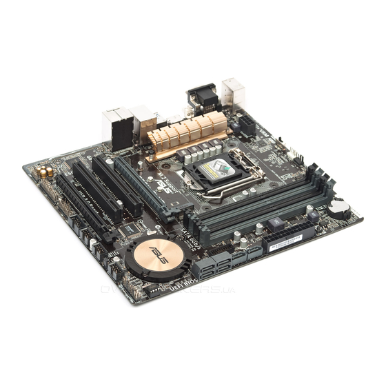
Page 18: Motherboard Layout
22.4cm(8.8in) CHA_FAN2 GPU Boost KBMS_USB78 CPU_FAN GPU_LED BATTERY DIGI +VRM EATX12V MemOK! DRAM_LED HDMI 1442K LGA1150 USB3_56 LAN_USB3_34 AUDIO CHA_FAN1 Z97M-PLUS PCIEX16_1 Intel I218-V PCI1 Intel ® Super 1083 PCI2 SB_PWR PCIEX16_2 SPDIF_OUT USB910 USB1112 USB1314 PANEL AAFP CLRTC Refer to 1.2.9 Internal connectors and 2.2.1 Rear I/O connection for more information about rear panel connectors and internal connectors. - Page 19 16. Serial port connector (10-1 pin COM) 1-16 17. TPM header (20-1 pin TPM) 1-19 18. Digital audio connector (4-1 pin SPDIF_OUT) 1-17 19. LPT connector (26-1 pin LPT) 1-20 20. Front panel audio connector (10-1 pin AAFP) 1-19 ASUS Z97M-PLUS...
-
Page 20: Central Processing Unit (Cpu)
Contact your retailer immediately if the PnP cap is missing, or if you see any damage to the PnP cap/socket contacts/motherboard components. ASUS will shoulder the cost of repair only if the damage is shipment/ transit-related. -
Page 21: System Memory
The motherboard comes with four Double Data Rate 3 (DDR3) Dual Inline Memory Modules (DIMM) slots. A DDR3 module is notched differently from a DDR or DDR2 module. DO NOT install a DDR or DDR2 memory module to the DDR3 slot. Z97M-PLUS Z97M-PLUS 240-pin DDR3 DIMM sockets Recommended memory configurations ASUS Z97M-PLUS... - Page 22 Memory configurations You may install 2GB, 4GB, and 8GB unbuffered and non-ECC DDR3 DIMMs into the DIMM sockets. memory from the higher-sized channel is then mapped for single-channel operation. the CPU. recommend that you obtain memory modules from the same vendor. ®...
-
Page 23: Expansion Slots
Z97M-PLUS PCIEX16_1 PCI1 PCI2 PCIEX16_2 Slot No. Slot Description PCIe 3.0/2.0 x16_1 slot (at x16 mode) PCI slot 1 PCI slot 2 PCIe 2.0 x16_2 slot (max. at x4 mode, compatible with PCIe x1 and x4 devices) ASUS Z97M-PLUS... - Page 24 PCIe Express operating mode VGA configuration PCIe 3.0/2.0 x16_1 PCIe 2.0 x16_2 Single VGA/PCIe card x16 (single VGA recommended) Dual VGA/PCIe card x16 graphics card to get better performance. using multiple graphics cards for better thermal environment. IRQ assignments for this motherboard PCIe x16_1 shared –...
-
Page 25: Jumpers
Normal Clear RTC (Default) Z97M-PLUS Clear RTC RAM Turn OFF the computer and unplug the power cord. Move the jumper cap from pins 1-2 (default) to pins 2-3. Keep the cap on pins 2-3 for about 5~10 seconds, then move the cap back to pins 1-2. -
Page 26: Onboard Buttons And Switches
BIOS default settings. A message will appear during POST reminding you that the BIOS has been restored to its default settings. ASUS website at www.asus.com after using the MemOK! function. 1-12 Chapter 1: Product introduction... - Page 27 Z97M-PLUS CPU Ratio Boost) CPU BCLK/Ratio Boost) Z97M-PLUS GPU Boost switch Boost), the system automatically adjusts the GPU and CPU ratio for an enhanced performance. Boost), the system automatically adjusts the GPU, base clock rate (BCLK) and the CPU ratio for a more enhanced performance.
-
Page 28: Onboard Leds
This user-friendly design provides an intuitional way to locate the root problem within a second. DRAM LED Z97M-PLUS Z97M-PLUS DRAM LED GPU Boost LED The GPU Boost LED lights up when the GPU Boost switch is enabled. GPU_LED Z97M-PLUS Z97M-PLUS GPU Boost LED 1-14 Chapter 1: Product introduction... -
Page 29: Internal Connectors
Rapid Storage Technology through the onboard Intel chipset. Z97M-PLUS Z97M-PLUS SATA 6.0Gb/s connectors AHCI] by default. If you intend to create a Serial ATA RAID set using these connectors, set the SATA Mode Selection item in the BIOS to RAID]. Refer to section 3.6.3 PCH Storage Configuration for details. - Page 30 IntA_P2_SSTX+ IntA_P1_D- IntA_P2_D- IntA_P1_D+ IntA_P2_D+ Z97M-PLUS USB3.0 Front panel connector ® related driver to fully use the USB 3.0 ports under Windows operating system’s setting. Serial port connector (10-1 pin COM) This connector is for a serial (COM) port. Connect the serial port module cable to this connector, then install the module to a slot opening at the back of the system chassis.
- Page 31 This connector is for an additional Sony/Philips Digital Interface (S/PDIF) port. Connect the S/PDIF Out module cable to this connector, then install the module to a slot opening at the back of the system chassis. Z97M-PLUS SPDIF_OUT Z97M-PLUS Digital audio connector The S/PDIF module is purchased separately. ASUS Z97M-PLUS 1-17...
- Page 32 CPU_FAN CHA_FAN2 CHA_FAN1 Z97M-PLUS Z97M-PLUS Fan connectors inside the system may damage the motherboard components. These are not jumpers! Do not place jumper caps on the fan connectors! Advanced Mode > Monitor > CPU Q-Fan Control item in BIOS. PWM, go to Advanced Mode > Monitor > Chassis Fan 1/2 Q-Fan Control items in BIOS.
- Page 33 Z97M-PLUS HD-audio-compliant Legacy AC’97 pin definition compliant definition Z97M-PLUS Front panel audio connector HD Audio AC97]. TPM connector (20-1 pin TPM) This connector supports a Trusted Platform Module (TPM) system, which securely network security, protect digital identities, and ensures platform integrity.
- Page 34 The system may become unstable or may not boot up if the power is inadequate. or above to ensure the system stability. refer to the Recommended Power Supply Wattage Calculator at http://support.asus. com/PowerSupplyCalculator/PSCalculator.aspx?SLanguage=en-us for details. LPT connector (26-1 pin LPT) The LPT (Line Printing Terminal) connector supports devices such as a printer.
- Page 35 Z97M-PLUS +HDD_LED- PWR_SW RESET Z97M-PLUS System panel connector This 2-pin connector is for the system power LED. Connect the chassis power LED cable to this connector. The system power LED lights up when you turn on the system power, and blinks when the system is in sleep mode.
- Page 36 M.2 Socket 3 This socket allows you to install an M.2 (NGFF) SSD module. M.2 (SOCKET3) Z97M-PLUS Z97M-PLUS M.2 socket 3.6.3 PCH Storage Configuration of this user guide for more details. ® Desktop Responsiveness technologies with PCIe M.2 device, ensure to set up the Windows ®...
-
Page 37: Chapter 2: Basic Installation
The diagrams in this section are for reference only. The motherboard layout may vary with models, but the installation steps are the same for all models. Install the ASUS I/O-shield to the chassis rear I/O panel. Place the motherboard into the chassis, ensuring that its rear I/O ports are aligned to the chassis’... - Page 38 Place six screws into the holes indicated by circles to secure the motherboard to the chassis. Z97M-PLUS DO NOT overtighten the screws! Doing so can damage the motherboard. Chapter 2: Basic installation...
-
Page 39: Cpu Installation
2.1.2 CPU installation Ensure that you install the correct CPU designed for LGA1150 socket only. DO NOT install a CPU designed for LGA1155 and LGA1156 socket on the LGA1150 socket. ASUS Z97M-PLUS... -
Page 40: Cpu Heatsink And Fan Assembly Installation
2.1.3 CPU heatsink and fan assembly installation Apply the Thermal Interface Material to the CPU heatsink and CPU before you install the heatsink and fan, if necessary. To install the CPU heatsink and fan assembly Chapter 2: Basic installation... - Page 41 To uninstall the CPU heatsink and fan assembly ASUS Z97M-PLUS...
-
Page 42: Dimm Installation
2.1.4 DIMM installation To remove a DIMM Chapter 2: Basic installation... -
Page 43: Atx Power Connection
2.1.5 ATX Power connection ASUS Z97M-PLUS... -
Page 44: Sata Device Connection
2.1.6 SATA device connection Chapter 2: Basic installation... -
Page 45: Front I/O Connector
2.1.7 Front I/O Connector To install the system panel connector To install USB 2.0 connector To install front panel audio connector AAFP USB 2.0 To install USB 3.0 connector USB 3.0 ASUS Z97M-PLUS... -
Page 46: Expansion Card Installation
2.1.8 Expansion Card installation To install PCIe x16 cards To install PCI cards 2-10 Chapter 2: Basic installation...