Table of Contents
Advertisement
Advertisement
Table of Contents

Related Manuals for Crestron MP2


Summary of Contents for Crestron MP2
- Page 1 Crestron MP2 & MP2E 2-Series Integrated AV Control System Operations Guide...
- Page 2 This document was prepared and written by the Technical Documentation department at: Crestron Electronics, Inc. 15 Volvo Drive Rockleigh, NJ 07647 1-888-CRESTRON All brand names, product names and trademarks are the property of their respective owners. ©2006 Crestron Electronics, Inc.
-
Page 3: Table Of Contents
Crestron MP2 & MP2E Contents 2-Series Integrated AV Control System: MP2 & MP2E Introduction ... 1 Features and Functions ... 1 Applications... 3 Internal Block Diagram ... 5 Specifications ... 6 Physical Description... 8 Industry Compliance ... 13 Setup ... 14 Network Wiring... -
Page 5: 2-Series Integrated Av Control System: Mp2 & Mp2E
• External power supply included • Single-space EIA rack-mountable latest version of the Crestron 2-Series Control Systems Reference Guide (Doc. 6256), which is available from the Crestron website (http://www.crestron.com/manuals). Series-2 Integrated AV Control System: MP2 & MP2E • 1 ®... - Page 6 2-Series Integrated AV Control System 2-Series Engine At the heart of the MP2 & MP2E is the powerful 32-bit Freescale ColdFire processor. Crestron's exclusive enhanced real-time operating system makes the MP2 & MP2E the fastest, most reliable control systems available.
-
Page 7: Applications
A/V switching and control and with an MMS multimedia switch. Example of a Basic Room Master Mode Configuration with A/V Switching and Control Operations Guide – DOC. 6175A 2-Series Integrated AV Control System Series-2 Integrated AV Control System: MP2 & MP2E • 3... - Page 8 2-Series Integrated AV Control System Crestron MP2 & MP2E Example of a Basic Room Master Mode Configuration with MMS Multimedia Switch 4 • 2-Series Integrated AV Control System: MP2 & MP2E Operations Guide – DOC. 6175A...
-
Page 9: Internal Block Diagram
Crestron MP2 & MP2E Internal Block Diagram The following diagram represents the AV switching abilities of the MP2 & MP2E. The diagram depicts the audio and video switching matrices and the equalization module available for the audio inputs. For more information refer to “Operation” on page 25. -
Page 10: Specifications
2-Series Integrated AV Control System Specifications Specifications for the MP2 & MP2E are listed in the following table. MP2 & MP2E Specifications (Continued on following page) 6 • 2-Series Integrated AV Control System: MP2 & MP2E SPECIFICATION Processor Processing Speed... - Page 11 PW-2420RU C2N-HBLOCK CNSP-XX IRP2 CNXRMIRD Series-2 Integrated AV Control System: MP2 & MP2E • 7 DETAILS ±12 dB, 0.1 dB steps from DMT; ±10 dB, 0.1 dB steps from SIMPL 63, 250, 1k, 4k, 10k Hz (5-band); 160, 600, 1k, 2.5k, 5k Hz (5-band speech);...
-
Page 12: Physical Description
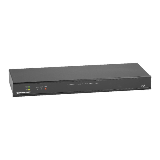
This section provides information on the connections, controls and indicators available on your MP2 & MP2E. MP2 Physical Views MP2E Physical Views 8 • 2-Series Integrated AV Control System: MP2 & MP2E Crestron MP2 & MP2E Operations Guide – DOC. 6175A... - Page 13 PW-2410RU power supply. Indicates communication with Cresnet system. Illuminates when a message is detected. To decipher content, examine the message through the Crestron Toolbox™. Series-2 Integrated AV Control System: MP2 & MP2E • 9 9.09 in (23.08 cm) 12 13 DESCRIPTION 1.70 in...
- Page 14 COM B GROUND (Continued on following page) 10 • 2-Series Integrated AV Control System: MP2 & MP2E LNK – Indicates when there is a connection to the rear panel LAN port. ACT – Indicates communication (activity) at the rear panel LAN port.
- Page 15 (1) 8-pin 3.5 mm detachable terminal block comprising (4) normally open, isolated relays; Rated 1 Amp, 30 Volts AC/DC, MOV arc suppression across contacts. Series-2 Integrated AV Control System: MP2 & MP2E • 11 DESCRIPTION SIGNALS balanced, 1.8 V unbalanced.
- Page 16 9. Use care in wiring installations to avoid applying 24 VDC to Cresnet wiring from an AC power pack as well as from a system device that contains its own power supply. Although this condition should not cause any damage, Crestron does not recommend it. In those network configurations that require more power than can be supplied by the primary power supply alone, disconnect the +24 VDC Cresnet wire from those devices that will be powered by an AC power pack.
-
Page 17: Industry Compliance
Crestron MP2 & MP2E Industry Compliance As of the date of manufacture the MP2 & MP2E have been tested and found to comply with specifications for CE marking and standards per EMC and Radiocommunications Compliance Labelling. NOTE: This device complies with part 15 of the FCC rules. Operation is subject to... -
Page 18: Setup
Identity Code Net ID The Net IDs of the MP2 & MP2E has been factory set to 02. This Net ID is defined as the “Master” control system. The Net IDs of multiple MP2 & MP2E devices in the same system must be unique; this means there will be a master/slave relationship between units (only the Net ID of the master will be left at 02). - Page 19 Crestron MP2 & MP2E Rack Mounting The MP2 & MP2E can be mounted in a rack or stacked with other equipment. Two “ears” are provided with the MP2 & MP2E so that the unit can be rack mounted. These ears must be installed prior to mounting. Complete the following procedure to attach the ears to the unit.
- Page 20 Refer to “Network Wiring” on page 14 before attaching the 4-position terminal block connector. Apply power after all connections have been made. When making connections to the MP2 & MP2E, consider the following: 16 • 2-Series Integrated AV Control System: MP2 & MP2E 1.
- Page 21 - CONTACT CLOSURES - RELAY CLOSURES included). If an alternate external power supply is to be used, Crestron recommends its CNPWS-75 External Power Supply or PW-2420RU Universal Power Pack or equivalent. Series-2 Integrated AV Control System: MP2 & MP2E • 17 24VDC, 2.0A:...
- Page 22 Balanced and Unbalanced Audio Connections on the Five Position Mini Connector SIGNAL NAME Balanced Audio Connections using a Five-Position Mini Connector 18 • 2-Series Integrated AV Control System: MP2 & MP2E A balanced input may use a balanced or unbalanced output. BALANCED BALANCED UNBALANCED AUDIO AUDIO...
- Page 23 NOTE: Using the unbalanced configuration for the audio output reduces the total audio gain by 6 dB. Operations Guide – DOC. 6175A 2-Series Integrated AV Control System Jumpers Left Right Series-2 Integrated AV Control System: MP2 & MP2E • 19 Chan 2 Chan 1...
-
Page 24: Programming Software
SystemBuilder from the Crestron website and examine the extensive help file. Programming with SIMPL Windows NOTE: While SIMPL Windows can be used to program the MP2 & MP2E, it is recommended to use SystemBuilder for configuring a system. SIMPL Windows is Crestron’s premier software for programming Crestron control systems. -
Page 25: Programming With Digital Media Tools
Operations Guide – DOC. 6175A 2-Series Integrated AV Control System • To incorporate the MP2 or MP2E into the system, drag the MP2 or MP2E from the Control Systems folder of the Device Library and drop it in the System Views. -
Page 26: Example Program
MUTE selection on the Tools Menu toggle MUTE on and off. Example Program An example program for the MP2 & MP2E is available from the Crestron website (http://www.crestron.com/exampleprograms). 22 • 2-Series Integrated AV Control System: MP2 & MP2E Crestron MP2 &... -
Page 27: Uploading And Upgrading
Use Crestron Toolbox for communicating with the MP2 & MP2E; refer to the Crestron Toolbox help file for details. With the MP2 the connection to the computer must be a direct serial connection; with the MP2E the connection can be either serial or TCP/IP. -
Page 28: Programs And Firmware
Alternatively, use a CAT5 crossover cable to connect the two LAN ports directly without using a hub or router. • Use the Address Book in the Crestron Toolbox to create an entry for the MP2E with the MP2E’s TCP/IP communication parameters. •... -
Page 29: Operation
The MP2 & MP2E both require 18 watts of power to operate. Therefore, if you use a PW-2410RU power supply (rated at 25 watts), you will have 7 watts of power left over to run additional Cresnet devices. -
Page 30: Problem Solving
The following table provides corrective action for possible trouble situations. If further assistance is required, please contact a Crestron customer service representative. MP2 & MP2E Troubleshooting (Continued on following page) 26 • 2-Series Integrated AV Control System: MP2 & MP2E TROUBLE POSSIBLE CAUSE(S) Unexpected Network devices are not... - Page 31 Mode” in the Crestron 2-Series Control Systems Reference Guide (Doc. 6256) System Monitor The System Monitor allows you to reload firmware into the MP2 & MP2E in the event that you cannot load the firmware in the normal mode. If the system does not function, perform the following procedure: Operations Guide –...
- Page 32 2-Series Integrated AV Control System NOTE: There are two methods for loading firmware through System Monitor (using Alt+O or using Alt+U). Because the first MP2 & MP2E firmware version 3.016 had special memory requirements, you must use the following Alt+U procedure when reverting to firmware version 3.016 from version 3.050 or when...
-
Page 33: Check Network Wiring
Crestron MP2 & MP2E Battery Replacement A Lithium battery is used to power the system clock within the MP2 & MP2E. Under normal conditions, it will last for approximately 10 years. In the event that the clock fails, only an authorized technician should replace it. Refer to caution statement below. -
Page 34: Reference Documents
For assistance in your local time zone, refer to the Crestron website (http://www.crestron.com/) for a listing of Crestron worldwide offices. You can also log onto the online help section of the Crestron website to ask questions about Crestron products. First-time users will need to establish a user account to fully benefit from all available features. -
Page 35: Software License Agreement
This Agreement may only be modified by a writing signed by an authorized officer of Crestron. Updates may be licensed to You by Crestron with additional or different terms. This is the entire agreement between Crestron and You relating to the Software and it supersedes any prior representations, discussions, undertakings, communications or advertising relating to the Software. - Page 36 “applets” incorporated into the Software), the accompanying media and printed materials and any copies of the Software are owned by Crestron or its suppliers. The Software is protected by copyright laws and international treaty provisions. Therefore, you must treat the Software like any other copyrighted material, subject to the provisions of this Agreement.
-
Page 37: Return And Warranty Policies
Purchasers should inquire of the dealer regarding the nature and extent of the dealer's warranty, if any. CRESTRON shall not be liable to honor the terms of this warranty if the product has been used in any application other than that for which it was intended or if it has been subjected to misuse, accidental damage, modification or improper installation procedures. - Page 38 2-Series Integrated AV Control System Crestron MP2 & MP2E This page is intentionally left blank. 34 • 2-Series Integrated AV Control System: MP2 & MP2E Operations Guide – DOC. 6175A...
- Page 39 Crestron MP2 & MP2E 2-Series Integrated AV Control System This page is intentionally left blank. Series-2 Integrated AV Control System: MP2 & MP2E • 35 Operations Guide – DOC. 6175A...
- Page 40 Crestron Electronics, Inc. Operations Guide – DOC. 6175A 15 Volvo Drive Rockleigh, NJ 07647 (2008838) Tel: 888.CRESTRON 08.06 Fax: 201.767.7576 Specifications subject to www.crestron.com change without notice.