Table of Contents
Advertisement
Quick Links
Advertisement
Table of Contents

Related Manuals for Crestron AV2


Summary of Contents for Crestron AV2
- Page 1 Crestron AV2 & PRO2 2-Series Integrated Dual Bus Control System Operations Guide...
- Page 2 This document was prepared and written by the Technical Documentation department at: Crestron Electronics, Inc. 15 Volvo Drive Rockleigh, NJ 07647 1-888-CRESTRON All brand names, product names and trademarks are the property of their respective owners. ©2002 Crestron Electronics, Inc.
-
Page 3: Table Of Contents
Crestron AV2 & PRO2 2-Series Integrated Dual Bus Control System Contents Integrated Dual Bus Control System: AV2 & PRO2 Introduction ..........................1 Features and Functions ....................1 Specifications ......................3 Physical Description....................4 On-Board Memory ....................13 Expandable Memory (Compact Flash)..............14 Industry Compliance .................... -
Page 5: Integrated Dual Bus Control System: Av2 & Pro2
Crestron’s AV2 and PRO2 2-Series Integrated Control Processors are designed for medium to large home and commercial network systems. Like all Crestron control processors, the AV2 and PRO2 units house the control system software program and provide connectivity for communication and control of all devices on the network. - Page 6 2-Series Integrated Dual Bus Control System Crestron AV2 & PRO2 As with all of Crestron’s 2-Series control processors, the 2-Series Control Engine is a solutions-driven control technology that is at the very heart of the AV2 and PRO2 Integrated Control Systems. With speed, power, and massive memory, the 2-Series control systems are ideal for enhanced applications like media help desks, videoconferencing, distance learning, and entertainment facilities.
-
Page 7: Specifications
Crestron AV2 & PRO2 2-Series Integrated Dual Bus Control System Specifications Specifications for the AV2 and PRO2 are given in the following table. AV2/PRO2 2-Series Integrated Control System Specifications SPECIFICATION DETAILS ® 32-Bit Motorola ColdFire Processor Processor Speed 257 MIPS (Dhrystone 2.1 Benchmark) -
Page 8: Physical Description
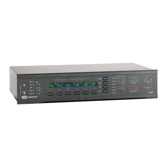
2-Series Integrated Dual Bus Control System Crestron AV2 & PRO2 Physical Description The AV2/PRO2 integrated control systems are housed in black enclosures with labeling on the front and rear panels. The dimensions shown in the following illustration apply to both units. - Page 9 The Z-BUS slot of both units is shown populated with a C2ENET-2 Ethernet Interface card. The AV2 is shown with the optional Y_BUS card cage installed-no cards mounted; the PRO2 is shown with the Y-BUS slots fully populated.
- Page 10 (ears). Refer to “Rack Mounting” on page 15 for details. Ports The ports provided on the front and rear panels of the AV2/PRO2 integrated control systems are described below. COM (A – F)
- Page 11 1A, 30 VAC/DC; MOV arc suppression is provided across contacts for use with "real world" loads. For detailed information, refer to RELAY OUTPUT “Slot 7: C2I-RY8” on page 32. Integrated Dual Bus Control System: AV2 & PRO2 • 7 Operations Guide - DOC. 5957A...
- Page 12 REAR PANEL 24 Y Z G This connector (typical Crestron network port labeled 24 Y Z G) is used for expansion to Cresnet devices. Depending on the expansion slot load, there is a 50 W maximum load rating. Refer to "Network Wiring" on page 17 for details.
- Page 13 SIMPL program. To the right of the display are four menu selection buttons. These buttons Integrated Dual Bus Control System: AV2 & PRO2 • 9 Operations Guide - DOC. 5957A...
- Page 14 Refer to the two arrows shown beneath the Info Menu illustrated after this note for location and identification. 10 • Integrated Dual Bus Control System: AV2 & PRO2 Operations Guide - DOC. 5957A...
- Page 15 NOTE: The up and down menu selection buttons to the right of the LCD screen may be used in lieu of the NEXT and PREV menu function buttons. MSG Submenu with Sample Message Integrated Dual Bus Control System: AV2 & PRO2 • 11 Operations Guide - DOC. 5957A...
- Page 16 (slot 4) and cards inserted into the expansion slots (e.g. CNXCOM-2 and C2COM- 3). Serial transmission to IR ports can also be monitored. Refer to "COM Analyzer" on page 41 for details. 12 • Integrated Dual Bus Control System: AV2 & PRO2 Operations Guide - DOC. 5957A...
-
Page 17: On-Board Memory
(not commented out) are monitored. On-Board Memory The AV2 and PRO2 each have 36MB of built-in memory (non-volatile and volatile). A total of 36MB is broken down as follows: 4MB flash (non-volatile), 32MB DRAM (volatile), and 256KB NVRAM (non-volatile memory). Flash memory contains the file system inside the 2-series control engine. -
Page 18: Expandable Memory (Compact Flash)
4. Observe handling precautions of the memory card manufacturer and remove card from the slot. 5. Align and reposition cover over slot and tighten the screw. 14 • Integrated Dual Bus Control System: AV2 & PRO2 Operations Guide - DOC. 5957A... -
Page 19: Industry Compliance
2-Series control system top cover. Using a #2 Phillips screwdriver, remove the three screws closest to the front panel from one side of the unit. Integrated Dual Bus Control System: AV2 & PRO2 • 15 Operations Guide - DOC. 5957A... -
Page 20: Bussing Strip Installation
5. Securing a tie wrap around the bussing strip is a useful way to strain relieve the wires connected to the terminal block. 16 • Integrated Dual Bus Control System: AV2 & PRO2 Operations Guide - DOC. 5957A... -
Page 21: Network Wiring
NOTE: When making wire connections, refer to the latest revision of the Cresnet Network Interconnect Drawing (Doc. 5411). The document can be obtained from the Downloads | Product Manuals section of the Crestron website (www. crestron.com). CAUTION: Possible equipment damage if miswired. -
Page 22: Hardware Hookup
NOTE: Since the plug on the power supply cord is used to disconnect power from the unit, the socket-outlet shall be installed near the equipment and shall be easily accessible. 18 • Integrated Dual Bus Control System: AV2 & PRO2 Operations Guide - DOC. 5957A... -
Page 23: Establishing Communication With The Av2/Pro2
- SOLID STATE CLOSURES Establishing Communication with the AV2/PRO2 Before uploading a program to the AV2/PRO2 or performing diagnostic functions, you must connect the control system to the PC. This connection can be serial or (if an optional Z-Bus card is installed) it can be TCP/IP. - Page 24 For TCP/IP, use CAT5 straight through cables with 8-pin RJ45 connectors to connect the LAN port on the AV2/PRO2 and the LAN port on the PC to the Ethernet hub. Alternatively, you can use a CAT5 crossover cable to connect the two LAN ports directly, without using a hub.
-
Page 25: Troubleshooting Communications
(e.g., for a modem). Consult the manufacturer’s documentation for further information about the COM ports on your 3. Check the ERR LED indicator on the front panel of the AV2/PRO2. If this LED is illuminated, unplug the unit and reapply power after a few seconds. -
Page 26: Compiling And Uploading A Program To The Control System
2-Series Integrated Dual Bus Control System Crestron AV2 & PRO2 Set the baud rate of the AV2/PRO2 control system to 115200, as follows: Press and release the HWR button on the unit’s front panel. Press and hold the SWR button for approximately three to five seconds. - Page 27 To delete the list, click Clear History. You can also click Check Program to display the header information of the currently loaded program. Integrated Dual Bus Control System: AV2 & PRO2 • 23 Operations Guide - DOC. 5957A...
-
Page 28: Uploading Web Pages To The Av2/Pro2
Uploading Web pages to the AV2/PRO2 The AV2/PRO2 provides a built-in Web server for e-Control applications. The AV2/PRO2 allots 2.5 MB of memory for “user files” such as Web pages, mailbox, and the compiled SPZ file. For detailed information, refer to “Uploading Web Pages”... -
Page 29: Updating The Operating System
Updating the Operating System As with all 2-Series control systems, operating system files for the AV2/PRO2 have a .cuz extension. You can obtain .cuz updates (when available) from the Software Downloads section of the Crestron website. To download an update, click the .cuz file and choose the Save to Disk option, then specify the directory where the update will be stored. -
Page 30: Other Compact-Flash-Related Functions
The SIMPL Windows online help file provides a full listing of console commands that are valid for 2-Series control systems. You can access the AV2/PRO2 console in a variety of ways: via a serial connection (RS-232) with a PC, over Ethernet via the LAN port, or through Telnet, among many other methods. -
Page 31: Programming The Av2 And Pro2
XGETFILE – Enables retrieving a file from compact flash. XPUTFILE – Enables sending a file to compact flash. Programming the AV2 and PRO2 You can create a program that allows you to control the AV2 or PRO2 control system using the Crestron programming tools Crestron Application Builder™ ®... -
Page 32: Programming With Simpl Windows
IR, serial communications, and/or relay ports to the control system. Slot 4: C2I-COM6 The AV2 and PRO2 provide six serial COM ports (A through F) that enable RS-232, RS-422, and RS-485 communication. 28 • Integrated Dual Bus Control System: AV2 & PRO2... - Page 33 To add an IR device to the system, drag the device driver from the Crestron or User IR Database to a C2I-IR8 port. To add an RS-232 device, drag the C2IR one-way serial driver from the Serial Drivers folder to a C2I-IR8 port.
- Page 34 Driving the corresponding <pu-disable> signal high can modify this behavior. This is not recommended, though, since it will cause the output pin to float when <o> goes low. 30 • Integrated Dual Bus Control System: AV2 & PRO2 Operations Guide - DOC. 5957A...
- Page 35 Rather, the <MinChange> signals should be used to specify a "minimum change" value, such that the C2I-IO8 will not propagate the new value until it changes by <MinChange>. (The default minimum change value is 2048.) Integrated Dual Bus Control System: AV2 & PRO2 • 31 Operations Guide - DOC. 5957A...
- Page 36 PDF on the Crestron website (www.Crestron.com). Slot 9: C2Net-Device The C2Net-Device slot enables the AV2 and PRO2 to control up to 252 Cresnet devices. Each Cresnet device is assigned a unique identifier called a Net ID, which is a hexadecimal value ranging from 03 to FE.
- Page 37 Although X-Series processors support ambiguous signals, the 2-Series processor requires all signal types to be strictly defined. If the program you want to convert contains SIMPL+ or User modules, Crestron recommends that you first convert each module before converting the larger program.
-
Page 38: Programming The Lcd Screen (Pro2 Only)
“Module Header Information” Window After you convert each module in a program, you can convert the program as described previously: drag the AV2/PRO2 onto the existing control system in System Views and click Yes to confirm the replacement. For further information about compile-time errors and detailed explanations about working with modules, refer to the SIMPL Windows online help file. - Page 39 VCR object. Simply click on the Add button and enter a new name for the new page. For this example, use “Menu2 – VCR Control” as the name. Integrated Dual Bus Control System: AV2 & PRO2 • 35 Operations Guide - DOC. 5957A...
- Page 40 NOTE: Pages on the Front Panel Editor can be assigned a join number to facilitate controlled page jumps. Use the “Front Panel Editor" window, as shown after this 36 • Integrated Dual Bus Control System: AV2 & PRO2 Operations Guide - DOC. 5957A...
- Page 41 Program View of SIMPL Windows’ Program Manager. The symbol appears in Detail View, as shown after this paragraph. Front Panel Symbol Displayed in SIMPL Windows’ Detail View of Programming Manager Integrated Dual Bus Control System: AV2 & PRO2 • 37 Operations Guide - DOC. 5957A...
-
Page 42: Problem Solving
The sample discussed in the previous sections utilizes only one of the object types available from the “Edit Panel Object” window, shown below. These object types are not new to Crestron programmers; the same types are available in VisionTools™ Pro-e. Object Type Area in the “Edit Panel Object” Window... - Page 43 (Parity), 8 (Data Bits) and 1 (Stop Bits) and click OK. 4. Power down the AV2/PRO2. 5. While powering up the AV2/PRO2, press and hold ALT and K on the keyboard until the following text (or similar) appears in Viewport: System Monitor [v1.001 (0001)]...
-
Page 44: Serial Communication Difficulties With Other Devices Connected To The Control System
The COM analyzer also functions while the unit is in passthrough mode. Passthrough mode is accessed from the Crestron Viewport by selecting Functions | Enter Passthrough Mode (CNX / 2-Series only). The window, shown after this paragraph, is used to select the port configuration for passthrough mode. - Page 45 Depressing the SELECT menu function button displays the Format Type screen, shown after this paragraph. Select the BIN, ASCII, or HEX menu function button to determine the appropriate format. Integrated Dual Bus Control System: AV2 & PRO2 • 41 Operations Guide - DOC. 5957A...
- Page 46 NOTE: The buffer recycles data even when in the 'freeze' state. When the screen is unfrozen, the display jumps to the end of the buffer. T/R Screen with Frozen Sample 42 • Integrated Dual Bus Control System: AV2 & PRO2 Operations Guide - DOC. 5957A...
-
Page 47: Further Inquiries
In Australia and New Zealand, call Crestron Pacific at +613-9480-2999. Firmware Upgrades To take advantage of all the AV2 and PRO2 features, it is important that the unit contains the latest firmware available. Therefore, please check our website (http://www.crestron.com/downloads/software_updates.asp) for the latest version of firmware. -
Page 48: Software License Agreement
This Agreement may only be modified by a writing signed by an authorized officer of Crestron. Updates may be licensed to You by Crestron with additional or different terms. This is the entire agreement between Crestron and You relating to the Software and it supersedes any prior representations, discussions, undertakings, communications or advertising relating to the Software. - Page 49 “applets” incorporated into the Software), the accompanying media and printed materials, and any copies of the Software are owned by Crestron or its suppliers. The Software is protected by copyright laws and international treaty provisions. Therefore, you must treat the Software like any other copyrighted material, subject to the provisions of this Agreement.
-
Page 50: Return And Warranty Policies
CRESTRON shall not be liable to honor the terms of this warranty if the product has been used in any application other than that for which it was intended, or if it has been subjected to misuse, accidental damage, modification, or improper installation procedures. - Page 51 Crestron AV2 & PRO2 2-Series Integrated Dual Bus Control System This page intentionally left blank. Integrated Dual Bus Control System: AV2 & PRO2 • 47 Operations Guide - DOC. 5957A...
- Page 52 Crestron Electronics, Inc. Operations Guide – DOC. 5957A 15 Volvo Drive Rockleigh, NJ 07647 08.02 Tel: 888.CRESTRON Fax: 201.767.7576 Specifications subject to www.crestron.com change without notice.