Table of Contents
Advertisement
Quick Links
Service Literature
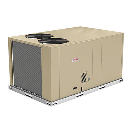
The ZHA commercial heat pump is available in 7.5, 8.5 and
10 ton capacities. The refrigerant systems utilize two com
pressors, two reversing valves, two accumulators, and
other parts common to a heat pump. Optional auxiliary
electric heat is factory or field installed. Electric heat oper
ates in single or multiple stages depending on the kW input
size. 7.5kW through 60kW heat sections are available.
Units are designed to accept any of several different energy
management thermostat control systems with minimum field
wiring.
Information contained in this manual is intended for use by
qualified service technicians only. All specifications are sub
ject to change. Procedures outlined in this manual are pre
sented as a recommendation only and do not supersede or
replace local or state codes.
If the unit must be lifted for service, rig unit by attaching four
cables to the holes located in the unit base rail (two holes at
each corner). Refer to the installation instructions for the proper
rigging technique.
WARNING
Improper installation, adjustment, alteration, ser
vice or maintenance can cause property damage,
personal injury or loss of life. Installation and ser
vice must be performed by a licensed professional
HVAC installer or equivalent service agency.
ELECTROSTATIC DISCHARGE (ESD)
Precautions and Procedures
CAUTION
Electrostatic discharge can affect electronic
components. Take precautions during unit instal
lation and service to protect the unit's electronic
controls. Precautions will help to avoid control
exposure to electrostatic discharge by putting
the furnace, the control and the technician at the
same electrostatic potential. Neutralize electro
static charge by touching hand and all tools on an
unpainted unit surface, such as the blower deck,
before performing any service procedure.
CAUTION
As with any mechanical equipment, contact with
sharp sheet metal edges can result in personal in
jury. Take care while handling this equipment and
wear gloves and protective clothing.
Corp. 1403-L4
Revised 05/2020
ZHA092 through 120
Page 1
ZHA SERIES
7.5 to 10 ton
26.3 to 35.2 kW
WARNING
Electric shock hazard. Can cause injury
or death. Before attempting to perform
any service or maintenance, turn the
electrical power to unit OFF at discon
nect switch(es). Unit may have multiple
power supplies.
. . . . . . . . . . . . . . . . . . . . . . .
. . . . . . . . . . . . . . . . . . . . . . . . . . . . . . .
. . . . . . . . . . . . . . . . . . . . . . . . . . . . . . . .
. . . . . . . . . . . . . . . . . . . . . . . . . . . . .
. . . . . . . . . . . . . . . . . . . . . . . . .
. . . . . . . . . . . . . . . . . . . . . . .
. . . . . . . . . . . . . . .
. . . . . . . . . . . . . . . . . . . . . . . . . . . . . . .
. . . . . . . . . . . . . . . . . . . . . . . . . . . . . .
. . . . . . . . . . . . . . . . .
. . . . . . . . . . . . . . . . . . . . . . . . . . .
. . . . . . . . . . . . . . . . . . . . . . . . . . . .
. . . . . . . . . . . . . . . . . . . . . . . .
Page 2
Page 5
Page 7
Page 11
Page 15
Page 16
Page 24
Page 24
Page 25
Page 28
Page 29
Page 31
Page 36
© 2014.
Advertisement
Table of Contents

Related Manuals for Lennox ZHA Series


Summary of Contents for Lennox ZHA Series
-
Page 1: Table Of Contents
ZHA SERIES Service Literature 7.5 to 10 ton Corp. 1403-L4 26.3 to 35.2 kW Revised 05/2020 ZHA092 through 120 The ZHA commercial heat pump is available in 7.5, 8.5 and 10 ton capacities. The refrigerant systems utilize two com pressors, two reversing valves, two accumulators, and other parts common to a heat pump. -
Page 2: Options / Accessories
OPTIONS / ACCESSORIES Unit Model No Model Catalog Item Description Number Number COOLING SYSTEM Condensate Drain Trap PVC - C1TRAP20AD2 76W26 Copper - C1TRAP10AD2 76W27 Corrosion Protection Factory Drain Pan Overflow Switch Z1SNSR90A1 99W59 Low Ambient Kit Z1SNSR33B-1 10Z34 Refrigerant Type R-410A BLOWER - SUPPLY AIR Blower Option... - Page 3 OPTIONS / ACCESSORIES Unit Model No Model Catalog Item Description Number Number INDOOR AIR QUALITY Air Filters 11H62 MERV 8 - Z1FLTR15B-1 Healthy Climate High Efficiency Air Filters ® 20 x 24 x 2 in. (Order 4 per unit) MERV 13 - Z1FLTR40B-1 11H63 Replacement Media Filter With Metal Mesh C1FLTR30B-1-...
- Page 4 OPTIONS / ACCESSORIES Unit Model No Model Catalog Item Description Number Number ECONOMIZER Standard Economizer (Not for Title 24) Standard Downflow Economizer with Single Temperature Control - Z1ECON30B-1 10Z29 With Barometric Relief Dampers and Air Hoods Z1ECON16B-1 11G98 Standard Horizontal Economizer with Single Temperature Control - With Barometric Relief Dampers and Air Hoods Standard Economizer Controls (Not for Title 24) Single Enthalpy Control...
-
Page 5: Specifications
SPECIFICATIONS 7.5 - 8.5 TON General Data Nominal Tonnage 7.5 Ton 7.5 Ton 8.5 Ton 8.5 Ton Model Number ZHA092S4B ZHA092S4M ZHA102S4B ZHA102S4M Efficiency Type Standard Standard Standard Standard Blower Type Constant Air MSAV (Multi-Stage Constant Air MSAV (Multi-Stage Volume (CAV) Air Volume) Volume (CAV) Air Volume) - Page 6 SPECIFICATIONS 10 TON General Data Nominal Tonnage 10 Ton 10 Ton Model Number ZHA120S4B ZHA120S4M Efficiency Type Standard Standard Blower Type Constant Air Volume (CAV) MSAV (Multi-Stage Air Volume) Cooling Gross Cooling Capacity - Btuh 121,900 121,900 Performance Net Cooling Capacity - Btuh 118,000 118,000 AHRI Rated Air Flow - cfm...
-
Page 7: Blower Data
BLOWER DATA 092S STANDARD EFFICIENCY BELT DRIVE BLOWER − BASE UNIT BLOWER TABLE INCLUDES RESISTANCE FOR BASE UNIT ONLY (NO HEAT SECTION) WITH DRY INDOOR COIL AND AIR FILTERS IN PLACE. FOR ALL UNITS ADD: 1 − Wet indoor coil air resistance of selected unit. 2 −... - Page 8 BLOWER DATA 102 AND 120S STANDARD EFFICIENCY BELT DRIVE BLOWER − BASE UNIT BLOWER TABLE INCLUDES RESISTANCE FOR BASE UNIT ONLY (NO HEAT SECTION) WITH DRY INDOOR COIL AND AIR FILTERS IN PLACE. FOR ALL UNITS ADD: 1 − Wet indoor coil air resistance of selected unit. 2 −...
- Page 9 BLOWER DATA FACTORY INSTALLED BELT DRIVE KIT SPECIFICATIONS Nominal Maximum Drive Kit Number RPM Range 590 - 890 800 - 1105 795 - 1195 3.45 730 - 970 3.45 940 - 1200 3.45 1015 - 1300 5.75 900 - 1135 5.75 1040 - 1315 5.75...
- Page 10 BLOWER DATA CEILING DIFFUSERS AIR RESISTANCE - in. w.g. RTD11 Step-Down Diffuser FD11 Flush Air Volume 1 Side, 2 Ends All Ends & Sides Diffuser Unit Size 2 Ends Open Open Open 2400 0.21 0.18 0.15 0.14 2600 0.24 0.21 0.18 0.17 2800...
-
Page 11: Electrical Data
ELECTRICAL/ELECTRIC HEAT DATA 7.5 TON 7.5 TON STANDARD EFFICIENCY ZHA 092S4 Voltage - 60hz 208/230V - 3 Ph 460V - 3 Ph 575V - 3 Ph Compressor 1 Rated Load Amps 13.5 Locked Rotor Amps Compressor 2 Rated Load Amps Locked Rotor Amps Outdoor Fan Full Load Amps... - Page 12 ELECTRICAL/ELECTRIC HEAT DATA 8.5 TON 8.5 TON STANDARD EFFICIENCY ZHA102S4 Voltage - 60hz 208/230V - 3 Ph 460V - 3 Ph 575V - 3 Ph Compressor 1 Rated Load Amps 13.5 Locked Rotor Amps Compressor 2 Rated Load Amps Locked Rotor Amps Outdoor Fan Full Load Amps Motors (2)
- Page 13 ELECTRICAL/ELECTRIC HEAT DATA 10 TON 10 TON STANDARD EFFICIENCY ZHA120S4 Voltage - 60hz 208/230V - 3 Ph 460V - 3 Ph 575V - 3 Ph Compressor 1 Rated Load Amps 15.6 Locked Rotor Amps 38.9 Compressor 2 Rated Load Amps 15.6 Locked Rotor Amps 38.9...
- Page 14 ELECTRIC HEAT CAPACITIES 7.5 kW 15 kW 22.5 kW 30 kW 45 kW 60 kW Volts Btuh No. of Btuh No. of Btuh No. of Btuh No. of Btuh No. of Btuh No. of Input Input Output Stages Input Output Stages Input Output...
-
Page 15: Parts Arrangement
ZHA PARTS ARRANGEMENT F4 FUSE 20 x 24 x 2” EVAPORATOR BLOCK FILTERS TB13 HIGH VOLTAGE COIL (OPTIONAL) INVERTER (BEHIND COIL) TERMINAL STRIP (OPTIONAL) TB1 LOW VOLTAGE TERMINAL STRIP BLOWER HOUSING CONDENSER FANS BLOWER MOTOR ELECTRIC HEAT (OPTIONAL) ELECTRIC HEAT CONTROLS CONDENSER TB2 TERMINAL... -
Page 16: I-Unit Components
I-UNIT COMPONENTS CONTACTOR The unit parts arrangement is shown in figure 1. All L1, L2, and L3 wiring is color coded; L1 is red, L2 is yellow, and L3 is blue. See wiring diagrams in the back of this manual for com plete call out of components. - Page 17 11-Low Ambient Kit Relay (K58) 14-Compressor Overload Relays S176, S177 (M-volt CE units) Low ambient relay K58 is a DPDT relay with a 24V coil ener Relays are wired in series with the appropriate compres gized by a CMC1 output in the heating cycle. K58-1 closes sor contactor and monitor the current flow to the compres...
- Page 18 defrost control will ignore the test pins. When the jumper is Defrost Control Board placed across the TEST pins for two seconds, the control The defrost thermostat, defrost pressure switch and the de will enter the defrost mode. If the jumper is removed before frost control work together to ensure that the heat pump an additional 5-second period has elapsed (7 seconds to...
- Page 19 ZHA 092,102, 120 PLUMBING AND COMPRESSOR CIRCUITS DETAIL INDOOR COIL STAGE 2 DRIERS (UPPER) OUTDOOR COIL STAGE 1 UPPER INDOOR COIL STAGE 1 (LOWER) OUTDOOR COIL STAGE 2 (LOWER) COMPRESSOR COMPRESSOR S104 DEFROST PRESSURE SWITCH S6 DEFROST COMPRESSOR 2 TEMPERATURE DISCHARGE SWITCH LINE...
- Page 20 B-Cooling Components 2-Thermal Protectors S5, S8 Units use independent cooling circuits consisting of sepa Some compressors have thermal protectors located on top rate compressors, outdoor coils and indoor coil (with 2 sep of the compressor. The protectors open at 248°F + 9°F arate stages).
- Page 21 6-Defrost Pressure Switch S104 CATIONS(table of contents) in the front of this manual. Units may be equipped with motors manufactured by vari The defrost pressure switch S104 is an auto‐reset SPST ous manufacturers, therefore electrical FLA and LRA spec N.C. pressure switch which opens on a pressure rise. The ifications will vary.
- Page 22 BLOWER ASSEMBLY SIDE VIEW TO INCREASE BELT TENSION 1- Loosen four bolts securing motor mounting base to frame. MOTOR ALLEN SCREW 2- Turn adjusting bolt to the right, or clockwise, to move the motor away from the blower housing. PULLEY IMPORTANT - Gap between end of frame and motor BLOWER mounting base should be equal at both ends, i.e.
- Page 23 LOCATION OF STATIC PRESSURE READINGS INSTALLATIONS WITH DUCTWORK INSTALLATIONS WITH CEILING DIFFUSERS ROOFTOP UNIT ROOFTOP UNIT RETURN AIR READING LOCATION RETURN AIR READING RE RE LOCATION SUPPLY SUPPLY TURN TURN FIRST BRANCH OFF OF MAIN RUN MAIN DUCT RUN SUPPLY AIR SUPPLY AIR READING READING...
-
Page 24: Ii-Placement And Installation
TABLE 3 MANUFACTURER'S NUMBERS DRIVE COMPONENTS DRIVE ADJUSTABLE SHEAVE FIXED SHEAVE BELT BROWNING NO. OEM PART NO. BROWNING NO. OEM PART NO. BROWNING NO. OEM PART NO. 1VP34x7/8 31K6901 AK61x1 100244-20 44L5501 1VP40x7/8 79J0301 AK59x1 31K6801 AX45 100245-23 1VP34x7/8 31K6901 AK46x1 100244-17 100245-18... -
Page 25: Iv-Charging
B-Refrigerant Charge and Check - Fin/Tube Coil IV-CHARGING WARNING-Do not exceed nameplate charge under any WARNING condition. This unit is factory charged and should require no further Refrigerant can be harmful if it is inhaled. Refrigerant adjustment. If the system requires additional refrigerant, re must be used and recovered responsibly. - Page 26 5- Add or remove charge in increments. Allow the system 7- Example ZHA092S Circuit 1: At 95°F outdoor ambient to stabilize each time refrigerant is added or removed. and a measured suction pressure of 130psig, the target liquid temperature is 103°F. For a measured liquid tem 6- Continue the process until measured liquid tempera...
- Page 27 TABLE 5 102S Normal Operating Pressures Outdoor Coil Entering Air Temperature 65 °F 75 °F 85 °F 95 °F 105 °F 115 °F Suct Disc Suct Disc Suct Disc Suct Disc Suct Disc Suct Disc (psig) (psig) (psig) (psig) (psig) (psig) (psig) (psig)
-
Page 28: V- System Service Checks
TABLE 6 120S Normal Operating Pressures Outdoor Coil Entering Air Temperature 65 °F 75 °F 85 °F 95 °F 105 °F 115 °F Suct Disc Suct Disc Suct Disc Suct Disc Suct Disc Suct Disc (psig) (psig) (psig) (psig) (psig) (psig) (psig) (psig) -
Page 29: Vi-Maintenance
VI-MAINTENANCE BACK OF UNIT The unit should be inspected once a year by a qualified ser LIFT UP AND PULL OUT (TOOLLESS) vice technician. FILTER ACCESS PANEL WARNING Electric shock hazard. Can cause injury or death. Before attempting to perform any service or maintenance, turn the electrical power to unit OFF at disconnect switch(es). - Page 30 D-Evaporator Coil G-Outdoor Coil Inspect and clean coil at beginning of each cooling season. Clean outdoor coil annually with detergent or commercial Clean using mild detergent or commercial coil cleanser. coil cleaner and inspect monthly during the cooling season. Flush coil and condensate drain with water taking care not Outdoor coils are made of single and two formed slabs.
-
Page 31: Vii-Accessories
VII-ACCESSORIES TYPICAL FLASHING DETAIL The accessories section describes the application of most of UNIT BASE the optional accessories which can be factory or field installed. BOTTOM OPTIONAL ACCESSORIES section (see table of contents) UNIT BASE RAIL show specific size per unit. A-LARMF Mounting Frames FIBERGLASS When installing units on a combustible surface for downflow... - Page 32 ECONOMIZER OUTDOOR COIL ECONOMIZER FIGURE 18 A6 Enthalpy Control LED'S MIXED AIR SENSOR (R1) LOCATION A steady green Free Cool LED indicates that outdoor air is suitable for free cooling. When an optional IAQ sensor is installed, a steady green R1 MIXED AIR SENSOR DCV LED indicates that the IAQ reading is higher than set...
- Page 33 Free Cooling Setpoint 1- Set thermostat to occupied mode if the feature is avail able. Make sure jumper is in place between TB1 termi nals R and OC if using a thermostat which does not Outdoor air is considered suitable when temperature and have the feature.
- Page 34 DCV Set and Max Settings Outdoor Air Not Suitable: During the unoccupied time period dampers are closed. Adjust settings when an optional IAQ sensor is installed. During the occupied time period a cooling demand will open The DCV SET potentiometer is factory-set at approxi dampers to minimum position and mechanical cooling mately 50% of the potentiometer range.
- Page 35 POWER EXHAUST FANS POWER ECONOMIZER EXHAUST FANS FIGURE 21 E-Power Exhaust Fan A6 ENTHALPY CONTROLLER The power exhaust fan (PEF) requires an optional gravity exhaust damper and economizer and is used in downflow ADJUST POWER applications only. See figure 21. The PEF provides exhaust EXHAUST FAN SETPOINT air pressure relief and also runs when return air dampers...
-
Page 36: Viii-Wiring Diagrams
VIII-Wiring Diagrams and Sequence of Operation ZHA UNIT DIAGRAM 7 14 Page 36... - Page 37 ZHA Sequence of Operation Power: First Stage Heat (compressors B1 and B2) 1- Line voltage from unit disconnect energizes transform 11- Heating demand energizes W1 in the thermostat. er T1 and T18. T1 provides 24VAC power to terminal 12- W1 demand energizes K8 relay coil which closes K8-2 strip TB1.
- Page 38 ELECTRONIC OR ELECTROMECHANICAL THERMOSTAT POWER: 1- Terminal strip TB1 energizes thermostat components with 24VAC. OPERATION: 2- TB1 receives data from the electronic thermostat A2 (Y1, Y2, W1, W2, G, OCP). The 24VAC signal from TB1 ener gizes the appropriate components for heat or cool demand. Page 38...
- Page 39 ECONOMIZER SEQUENCE OF OPERATION POWER: 1- Terminal strip TB1 energizes the economizer components with 24VAC. OPERATION: 2- Enthalpy sensor A7 and A62 (if differential enthalpy is used) communicates to the economizer control module A6 when to power the damper motor B7. 3- Economizer control module A6 supplies B7 with 0 - 10 VDC to control the positioning of economizer.
- Page 40 EHA-7.5, 15, 22.5, 30, 45 & 60kW Y VOLTAGE ZHA SERIES UNITS Heat 2 (W2) 24V Power (R) 24V Common (C) Page 40...
- Page 41 EHA-7.5, 15, 22.5, 30, 45 & 60kW G, J VOLTAGE ZHA SERIES UNITS Heat 2 (W2) 24V Power (R) 24V Common (C) Page 41...
- Page 42 Sequence of Operation - EHA 7.5, 15, 22.5, 30, 45, 60 kW - Y and G, J, M NOTE: This sequence of operation is for all Electric 4- N.O. contacts K15-1 close allowing the first bank of ele ments to be energized. Heat kW ratings Y through J voltages.
- Page 43 TYPICAL MSAV UNIT DIAGRAM Page 43...
- Page 44 MSAV BLOWER OPERATION G Blower Demand: 5- The blower demand closes K117 N.O. contacts. 24VAC is routed through K117 and K186 closed con 1- 24VAC is routed from thermostat blower G. tacts to A96 inverter terminal RH. Blower operates in 2- K117 relay is energized.