Advertisement
Quick Links
Advertisement

Related Manuals for Gigabyte H262-ZL2


Summary of Contents for Gigabyte H262-ZL2
- Page 1 Liquid Cooling Module (for H262-ZL2 and H262-ZL0) User Guide Rev. 1.0...
- Page 2 GIGABYTE's prior written permission. Documentation Classifications In order to assist in the use of this product, GIGABYTE provides the following types of documentation: User Manual: detailed information & steps about the installation, configuration and use of this product (e.g.
-
Page 3: Table Of Contents
Table of Contents Chapter 1 Hardware Installation ..................5 Installation Precautions ..................5 Package Contents .................... 6 Installing the Liquid Cooling Module (H262-ZL2) ..........8 Installing the Liquid Cooling Module (H262-ZL0) ........... 26 - 3 -... - Page 4 This page intentionally left blank - 4 -...
-
Page 5: Chapter 1 Hardware Installation
Chapter 1 Hardware Installation Installation Precautions The motherboard/system contain numerous delicate electronic circuits and components which can become damaged as a result of electrostatic discharge (ESD). Prior to installation, carefully read the service guide and follow these procedures: • Prior to installation, do not remove or break motherboard S/N (Serial Number) sticker or warranty sticker provided by your dealer. -
Page 6: Package Contents
Package Contents When unpacking please check you have the following items. If any are missing or damaged, please contact the place of purchase for a replacement. Retain the box and packaging in case you need to transport your liquid cooling module in the future. The fitted foam packing is ideal for protecting the device during transport. Liquid Cooling Module Packing Box (H262-ZL2) QSFP Connector CPU Coolant Coolant Pipe DIMM Heatsink Heatsink Heatsink DIMM Heatsink... - Page 7 Server System Packing Box Accessory Box Support Brackets and Screws - 7 - Hardware Installation...
-
Page 8: Installing The Liquid Cooling Module (H262-Zl2)
Installing the Liquid Cooling Module (H262-ZL2) Before you remove or install the liquid cooling module: • Make sure the system is not turned on or connected to AC power. Follow these instructions to install the liquid cooling module: Remove the two PCIe brackets. PCIE 2 PCIE 1 Remove PCIe Slot 1 screws. Hardware Installation - 8 -... - Page 9 Remove PCIe Slot 2 screws. Attach support brackets to the system. Accessory Box Support Brackets and Screws KT-2 KT-1 25HB4-H26231-H4R 25HB4-H26230-H4R - 9 - Hardware Installation...
- Page 10 Secure the support brackets with screws. Hardware Installation - 10 -...
- Page 11 Install CPU before installing the Liquid cooling module. NOTE! • The CPU cooling block has pre-applied thermal paste, so no need to apply additional paste unless reseating the cooler. • Make sure all DIMM slot latches are all in a locked position. Hold the liquid cooling module acrylic protector horizontally and remove it from the package box.
- Page 12 Align the liquid cooling module and place it on the top of the compute node. Secure the CPU coolant heatsink with screws. NOTE! To remove /install the coolant module screws, use a hex socket cap screwdriver with a screw torque of 10kgf-cm. Hardware Installation - 12 -...
- Page 13 Remove the screws shown below, and securely remove the acrylic protector from the liquid cooling module. NOTE! Retain the acrylic protector and packaging in case you need to transport your liquid cooling module in the future. - 13 - Hardware Installation...
- Page 14 Secure the liquid cooling module with screws. (25KS6-130102-S0R SCREW*6) Hardware Installation - 14 -...
- Page 15 Secure the LAN card heatsink with screws. (2598EG-1C001-S00 screw *4) Remove PCIe 1 bracket screw and remove the bracket. NOTE! Retain the screw. - 15 - Hardware Installation...
- Page 16 Put the Coolant pipe through the PCIe 1 bracket. Put the PCIe bracket and coolant bracket together. Use the retained screw to lock the PCIe 1 bracket. Hardware Installation - 16 -...
- Page 17 Install the related heatsink for LAN card. Remove the orignal heatsink on the LAN card. - 17 - Hardware Installation...
- Page 18 To remove the heatsink, push the spring screw inward to remove the heatsink. NOTE! • After removing the heatsink, clean the thermal paste on the heatsink. • Retain the four spring screws. Hardware Installation - 18 -...
- Page 19 Push Push Remove the original heatsink on the QSFP connector. Remove the bracket to remove the heatsink. NOTE! Retain the bracket. - 19 - Hardware Installation...
- Page 20 Heatsink Bracket Install the LAN card chip heatsink. Secure the heatsink with four spring screws. Hardware Installation - 20 -...
- Page 21 Install the QSFP connector heatsink. Attach the heatsink on the QSFP connector. Push the bracket into connector to secure the heatsink. - 21 - Hardware Installation...
- Page 22 Remove PCIe Slot 2 screws and remove the support bracket. NOTE! Retain the screws and the support bracket. Hardware Installation - 22 -...
- Page 23 Remove the PCIe bracket. Align the LAN card to the PCIe slot and push in the direction of the arrow until the LAN card sits in the connector. Secure the LAN card with screw. - 23 - Hardware Installation...
- Page 24 Secure the support bracket with screw. Re-install the PCIe riser into the compute node and secure the riser with screws. Hardware Installation - 24 -...
- Page 25 NOTE! Install PCIe 2 riser first, then install PCIe 1 riser. PCIE 2 PCIE 1 Use the DIMM latch tool to open the DIMM latches. - 25 - Hardware Installation...
-
Page 26: Installing The Liquid Cooling Module (H262-Zl0)
Installing the Liquid Cooling Module (H262-ZL0) Before you remove or install the liquid cooling module: • Make sure the system is not turned on or connected to AC power. Follow these instructions to install the liquid cooling module: Remove the two PCIe brackets. PCIE 2 PCIE 1 Remove PCIe Slot 1 screws. Hardware Installation - 26 -... - Page 27 Remove PCIe Slot 2 screws. Install CPU before installing the Liquid cooling module. NOTE! • The CPU cooling block has pre-applied thermal paste, so no need to apply additional paste unless reseating the cooler. • Make sure all DIMM slot latches are all in a locked position. Remove the liquid cooling module from the package box.
- Page 28 Secure the CPU coolant heatsink with screws. NOTE! To remove /install the coolant module screws, use a hex socket cap screwdriver with a screw torque of 10kgf-cm. Remove PCIe 1 bracket screw and remove the bracket. NOTE! Retain the screw. Hardware Installation - 28 -...
- Page 29 Put the Coolant pipe through the PCIe 1 bracket. Put the PCIe bracket and coolant bracket together. Use the retained screw to lock the PCIe 1 bracket. - 29 - Hardware Installation...
- Page 30 Re-install the PCIe riser into the compute node and secure the riser with screws. NOTE! Install PCIe 2 riser first, then install PCIe 1 riser. PCIE 2 PCIE 1 Hardware Installation - 30 -...
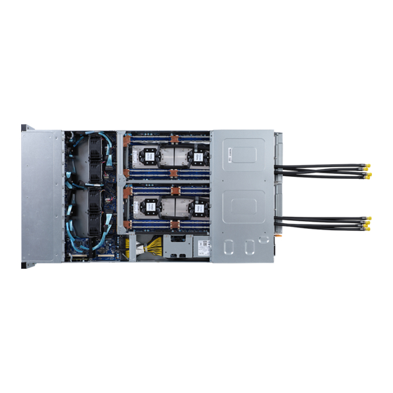
- Page 31 Installation completed. NOTE! Make sure the cable tie is placed horizontally with the coolant pipe. - 31 - Hardware Installation...