Table of Contents
Advertisement
Quick Links
Advertisement
Table of Contents

Related Manuals for Gigabyte H261-Z60


Summary of Contents for Gigabyte H261-Z60
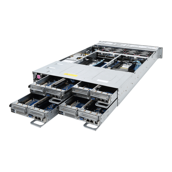
- Page 1 H261-Z60 H261-Z61 HCI Server – AMD DP 2U 4 Nodes Server User Manual Rev.B00...
- Page 2 GIGABYTE's prior written permission. Documentation Classifications In order to assist in the use of this product, GIGABYTE provides the following types of documentation: User Manual: detailed information & steps about the installation, configuration and use of this product (e.g.
- Page 3 Conventions The following conventions are used in this user's guide: NOTE! Gives bits and pieces of additional information related to the current topic. CAUTION! Gives precautionary measures to avoid possible hardware or software problems. WARNING! Alerts you to any damage that might result from doing or not doing specific actions.
- Page 4 Server Warnings and Cautions Before installing a server, be sure that you understand the following warnings and cautions. WARNING! To reduce the risk of electric shock or damage to the equipment: • Do not disable the power cord grounding plug. The grounding plug is an important safety feature.
- Page 5 Electrostatic Discharge (ESD) CAUTION! ESD CAN DAMAGE DRIVES, BOARDS, AND OTHER PARTS. WE RECOMMEND THAT YOU PERFORM ALL PROCEDURES AT AN ESD WORKSTATION. IF ONE IS NOT AVAILABLE, PROVIDE SOME ESD PROTECTION BY WEARING AN ANTI-STATIC WRIST STRAP AT- TACHED TO CHASSIS GROUND -- ANY UNPAINTED METAL SURFACE -- ON YOUR SERVER WHEN HANDLING PARTS.
- Page 6 Installing or removing jumpers: A jumper is a small plastic encased conductor that slips over two jumper pins. Some jumpers have a small tab on top that can be gripped with fin-gertips or with a pair of fine needle nosed pliers. If the jumpers do not have such a tab, take care when us- ing needle nosed pliers to remove or install a jumper;...
-
Page 7: Table Of Contents
Table of Contents Chapter 1 Hardware Installation ................... 11 Installation Precautions .................. 11 Product Specifications ..................12 System Block Diagram ................... 17 Chapter 2 System Appearance ..................19 Front View ...................... 19 Rear View ....................... 19 Front Panel LED and Buttons ................ 20 2-3-1 RoT LEDs .......................21 Power Supply Unit (PSU) LED ............... - Page 8 Motherboard Components ................47 Jumper Setting ....................48 Chapter 5 BIOS Setup ....................49 The Main Menu ....................51 Advanced Menu ..................... 53 5-2-1 Trusted Computing ....................54 5-2-2 PSP Firmware Versions ..................55 5-2-3 Legacy Video Select ....................56 5-2-4 AST2500 Super IO Configuration ................57 5-2-5 S5 RTC Wake Settings ...................58 5-2-6...
- Page 9 Security Menu ....................97 5-7-1 Secure Boot ......................98 Boot Menu ....................100 Save & Exit Menu ..................102 - 9 -...
- Page 10 This page intentionally left blank - 10 -...
-
Page 11: Chapter 1 Hardware Installation
Chapter 1 Hardware Installation Installation Precautions The motherboard/system contain numerous delicate electronic circuits and components which can become damaged as a result of electrostatic discharge (ESD). Prior to installation, carefully read the service guide and follow these procedures: • Prior to installation, do not remove or break motherboard S/N (Serial Number) sticker or warranty sticker provided by your dealer. -
Page 12: Product Specifications
Product Specifications System 2U 4 Nodes - Rear access Š Dimension 440 (W) x 87(H) x 820(D) mm Š AMD EPYC™ 7003 series processor family Š Dual processors, 7nm, Socket SP3 Š Up to 64-core, 128 threads per processor Š TDP up to 200W Š... - Page 13 Management chip in CMC board: Š Integrated in Aspeed® AST2520A2-GP Š Storage Per node: (H261-Z60) 6 x 2.5" SATA hot-swappable HDD/SSD onboard SATA ports Š 4 x 2.5" SATA /SAS hot-swappable HDD/SSD with SAS RAID Card Š Total: 24 x 2.5" hot-swappable HDD/SSD bays Š...
- Page 14 Per node: Front I/O 1 x Power button with LED Š 1 x ID button with LED Š 1 x Status LED Š Total: 4 x Power button with LED Š 4 x ID button with LED Š 4 x Status LED Š...
- Page 15 System Aspeed® AST2500 management controller Š Management GIGABYTE Management Console (AMI MegaRAC SP-X) web interface Š Dashboard Š JAVA Based Serial Over LAN Š HTML5 KVM Š Sensor Monitor (Voltage, RPM, Temperature, CPU Status …etc.) Š Sensor Reading History Data Š...
- Page 16 Ambient Operating temperature: 10°C to 35°C Š Operating humidity: 8-80% (non-condensing) Temperature Š Non-operating temperature: -40°C to 60°C Š Relative Non-operating humidity: 20%-95% (non-condensing) Š Humidity * We reserves the right to make any changes to the product specifications and product-related information without prior notice.
-
Page 17: System Block Diagram
System Block Diagram H261-Z60 Up to 3200/2933 MHz Up to 3200/2933 MHz CPU_0 10.6GT/s; 11.7GT/s; 12.8GT/s CPU_1 4x16 GOP 6 x SATAIII SlimLine SAS 8 Channels 8 Channels DDR4 DDR4 AMD MILAN AMD MILAN “Zen3” Core “Zen3” Core OCP Mezzanine PCIe3.0 x16... - Page 18 This page intentionally left blank Hardware Installation - 18 -...
-
Page 19: Chapter 2 System Appearance
Chapter 2 System Appearance Front View H261-Z60 Node 1 Node 2 Node 3 Node 4 H261-Z61 Node 1 Node 2 Node 3 Node 4 Decription Front Panel LEDs and buttons NOTE! The Orange Latche Supports NVMe • Orange HDD latch supports NVMe. -
Page 20: Front Panel Led And Buttons
Front Panel LED and Buttons No. Name Color Status Description Green System is operating normally. Critical condition, may indicates: System fan failure System temperature Non-critical condition, may indicates: Amber System Status Redundant power module failure Blink (Note) Temperature and voltage issue Chassis intrusion Non-critical condition, may indicates: Redundant power module failure... -
Page 21: Rot Leds
2-3-1 RoT LEDs ID LED Status LED LED on Front panel (Note5) ID LED Status LED EC Firmware (FW) Authentication fail or not exit EC FW is broken or not exit (Note1) Authenticating/Recovering BMC/BIOS Images Authenticating Images Blinks Blue Blinks Green Recovering BMC Active Flash 4 times per second 4 times per second... - Page 22 Active Flash Authentication (AUTH) Fail Blinks Blue Blinks Green BMC : AUTH Fail (Note2) 1 time per second 1 time per second Blinks Blue Blinks Amber BIOS : AUTH fail (Note2) 1 time per second 1 time per second Blinks Blue Blinks Green 2 times per second 2 times per second...
-
Page 23: Power Supply Unit (Psu) Led
Power Supply Unit (PSU) LED PSU LED State Description Indicates no AC power to all power supplies 0.5Hz Blink GREEN Indicates AC present/ only standby on/ Cold redundant mode 2Hz Blink GREEN Indicates power supply firmware in updating mode Indicates AC cord unplugged or AC power lost; with a second power supply in parallel still with AC input power Amber Indicates power supply critical event causing shut down:... -
Page 24: Rear System Lan Leds
Rear System LAN LEDs Name Color Status Description Yellow 1Gbps data rate 1GbE Green 100 Mbps data rate Speed LED 10 Mbps data rate Link between system and 1GbE Green network or no access Link/ Blink Data transmission or receiving is occurring Activity LED No data transmission or receiving is occurring System Appearance... -
Page 25: Hard Disk Drive Leds
Hard Disk Drive LEDs HDD Present RAID SKU LED1 Locate HDD Fault Rebuilding Access (No Access) Disk LED Green ON(*1) BLINK (*2) (LED on Back Panel) Amber No RAID configuration ON(*1) Green (via HBA) Removed HDD Slot (LED on Back Panel) Amber Green BLINK (*2) - Page 26 This page intentionally left blank System Appearance - 26 -...
-
Page 27: Chapter 3 System Hardware Installation
Chapter 3 System Hardware Installation Pre-installation Instructions Computer components and electronic circuit boards can be damaged electrostatic discharge. Working on computers that are still connected to a power supply can be extremely dangerous. Follow the simple guidelines below to avoid damage to your computer or injury to yourself. -
Page 28: Installing The Hard Disk Drive
Installing the Hard Disk Drive Read the following guidelines before you begin to install the Hard disk drive: • Take note of the drive tray orientation before sliding it out. • The tray will not fit back into the bay if inserted incorrectly. •... -
Page 29: Removing The Node
Removing the Node Before you remove or install the node • Make sure the system is not turned on or connected to AC power. Follow these instructions to remove a node: Press the retaining clip on the right side of the node along the direction of the arrow, while pulling out the node using its handle. -
Page 30: Removing Chassis Cover
Removing Chassis Cover Before you remove or install the system cover • Make sure the system is not turned on or connected to AC power. Follow these instructions to remove the system cover: Loosen and remove the six screws securing the back cover. Slide the cover to the rear of the system and remove the cover in the direction of the arrow. -
Page 31: Removing And Installing The Fan Duct
Removing and Installing the Fan Duct Follow these instructions to remove/install the fan duct: Remove the four screws securing the fan ducts. Lift up to remove the fan ducts To install the fan duct, align the fan duct with the guiding groove. Push down the fan duct into chassis until its firmly seats, then install the four screws to secure the fan ducts in place. -
Page 32: Removing And Installing The Heatsink
Removing and Installing the Heatsink Read the following guidelines before you begin to install the heatsink: • Always turn off the computer and unplug the power cord from the power outlet before installing the heatsink to prevent hardware damage. • Unplug all cables from the power outlets. •... - Page 33 Secondary CPU Heatsink: To install the heatsink, reverse the steps above while ensuring that you tighten the captive screws in sequential order (1g2g3g4) as seen in the image below. Primary CPU Heatsink Secondary CPU Heatsink: - 33 - System Hardware Installation...
-
Page 34: Installing The Cpu
Installing the CPU Read the following guidelines before you begin to install the CPU: • Make sure that the motherboard supports the CPU. • Always turn off the computer and unplug the power cord from the power outlet before installing the CPU to prevent hardware damage. •... -
Page 35: Installing Memory
Installing Memory Read the following guidelines before you begin to install the memory: • Make sure that the motherboard supports the memory. It is recommended that memory of the same capacity, brand, speed, and chips be used. • Always turn off the computer and unplug the power cord from the power outlet before installing the memory to prevent hardware damage. -
Page 36: Installing The Memory
3-7-2 Installing the Memory Before installing a memory module, make sure to turn off the computer and unplug the power cord from the power outlet to prevent damage to the memory module. Be sure to install DDR4 DIMMs on this motherboard. Follow these instructions to install the Memory: Insert the DIMM memory module vertically into the DIMM slot, and push it down. -
Page 37: Dimm Population Table
3-7-4 DIMM Population Table EPYC Memory Speed based on DIMM Population (One DIMM per Channel) DIMM Population DIMM Max EPYC 7003 DIMM 0 Type DDR Frequency (MHz) 1R (1 Rank) 3200 RDIMM 2R or 2DR (2 Ranks) 3200 4DR (4 Ranks) 3200 2S2R (4 Ranks) 3200... - Page 38 NOTE! l 1R: 1 package rank of SDP DRAMs l 2R: 2 package rank of SDP DRAMs l 2DR: 2 package rank of DDP DRAMs l 4DR: 4 package rank of DDP DRAMs l 2S2R/2S4R/2S8R: 2 package rank of 2/4/8 high 3DS DRAMs l DIMM must be populated in sequential alphabetic order, starting with bank A.
-
Page 39: Installing The Pci Expansion Card
Installing the PCI Expansion Card • Voltages can be present within the server whenever an AC power source is connected. This voltage is present even when the main power switch is in the off position. Ensure that the system is powered-down and all power sources have been disconnected from the server prior to installing a PCI card. - Page 40 Follow these instructions to install the right PCI Expansion card: Remove the two screws on the riser bracket to the system. Lift up the riser bracket out of system. Remove the screw securing the side bracket to the riser bracket. Remove the side bracket Align the PCIe card to the riser guide slot and push in the direction of the arrow until the PCIe card sits in the PCI card connector.
-
Page 41: Installing The Ocp Card
Installing the OCP Card • Voltages can be present within the server whenever an AC power source is connected. This voltage is present even when the main power switch is in the off position. Ensure that the system is powered-down and all power sources have been disconnected from the server prior to installing a OCP card. -
Page 42: Replacing The Fan Assembly
3-10 Replacing the Fan Assembly Follow these instructions to replace the fan assembly: Pull the fan ear outward. Lift up the fan assembly from the chassis. Reverse the previous steps to install the replacement fan assembly. System Hardware Installation - 42 -... -
Page 43: Replacing The Power Supply
3-11 Replacing the Power Supply Before you remove or install the system cover • Make sure the system is not turned on or connected to AC power. Follow these instructions to replace the power supply: Pull up the power supply handle and press the retaining clip on the right side of the power supply along the direction of the arrow. -
Page 44: Replacing Power Distribution Board Cage
3-12 Replacing Power Distribution Board Cage Before you remove or install the power distribution board cage: • Make sure the system is not turned on or connected to AC power. Follow these instructions to remove the power distribution board cage: Loosen and remove the four screws securing the cage. -
Page 45: Cable Routing
3-13 Cable Routing Suggest Cable Suggest Cable Front switch cable/Front LED cable On board SATA signal cable (Brown) (Purple) PDB to Node bridge board power cable PDB signal cable (Light Green) (Dark Green) LAN bridge board cable System fan power cable (Yellow-Green) (Black) - 45 -... -
Page 46: Hard Drive Back Plane Board Cable Routing
3-13-1 Hard Drive Back Plane Board Cable Routing Node1 Node3 Node2 Node4 Suggest Cable Suggest Cable SATA cable #0~#3 SATA cable #12~#15 NVME SSD cable #4~#5 NVME SSD cable #16~#17 (Defined by SKU) (Defined by SKU) SATA cable #6~#9 SATA cable #18~#21 NVME SSD cable #10~#11 NVME SSD cable #22~#23 (Defined by SKU) -
Page 47: Chapter 4 Motherboard Components
Chapter 4 Motherboard Components Motherboard Components DIMM_P0_H0 DIMM_P1_L0 DIMM_P0_G0 DIMM_P1_K0 DIMM_P0_F0 DIMM_P1_J0 DIMM_P0_E0 DIMM_P1_I0 SATA SGPIO#A CPU0 CPU1 SATA SGPIO#B DIMM_P0_A0 DIMM_P1_M0 DIMM_P0_B0 DIMM_P1_N0 DIMM_P0_C0 DIMM_P1_O0 DIMM_P0_D0 DIMM_P1_P0 10 11 12 Item Description USB 3.0 ports IPMB connector NCSI switch Serial port connector VGA port Riser slot #2 (Gen 3/x16 slot) -
Page 48: Jumper Setting
Jumper Setting Default Enable Clear CMOS CLR_CMOS 1 2 3 Motherboard Components - 48 -... -
Page 49: Chapter 5 Bios Setup
Chapter 5 BIOS Setup BIOS (Basic Input and Output System) records hardware parameters of the system in the EFI on the motherboard. Its major functions include conducting the Power-On Self-Test (POST) during system startup, saving system parameters and loading operating system, etc. BIOS includes a BIOS Setup program that allows the user to modify basic system configuration settings or to activate certain system features. - Page 50 Main This setup page includes all the items in standard compatible BIOS. Advanced This setup page includes all the items of AMI BIOS special enhanced features. (ex: Auto detect fan and temperature status, automatically configure hard disk parameters.) ...
-
Page 51: The Main Menu
The Main Menu Once you enter the BIOS Setup program, the Main Menu (as shown below) appears on the screen. Use arrow keys to move among the items and press <Enter> to accept or enter other sub-menu. Main Menu Help The on-screen description of a highlighted setup option is displayed on the bottom line of the Main Menu. - Page 52 Parameter Description BIOS Information Project Name Displays the project name information. Project Version Displays version number of the BIOS setup utility. Build Date and Time Displays the date and time when the BIOS setup utility was created. BMC Information BMC Firmware Version Displays version number of the BIOS setup utility.
-
Page 53: Advanced Menu
Advanced Menu The Advanced menu display submenu options for configuring the function of various hardware components. Select a submenu item, then press [Enter] to access the related submenu screen. - 53 - BIOS Setup... -
Page 54: Trusted Computing
5-2-1 Trusted Computing Parameter Description Configuration Select Enabled to activate TPM support feature. Security Device Support Options available: Enabled/Disabled. Default setting is Disabled. SPI TPM Support Options available: Enabled/Disabled. Default setting is Enabled Options available: Enabled/Disabled. Default setting is Disabled. Disable Block Sid BIOS Setup - 54 -... -
Page 55: Psp Firmware Versions
5-2-2 PSP Firmware Versions The PSP Firmware Versions page displays the basic PSP firmware version information. Items on this window are non-configurable. - 55 - BIOS Setup... -
Page 56: Legacy Video Select
5-2-3 Legacy Video Select Parameter Description Select between onboard or external VGA support. OnBrd/Ext VGA Select Options available: Auto/Onboard/External. Default setting is Onboard. BIOS Setup - 56 -... -
Page 57: Ast2500 Super Io Configuration
5-2-4 AST2500 Super IO Configuration Parameter Description AST2500 Super IO Configuration Super IO Chip Serial Port 1/2 Press [Enter] for configuration of advanced items. Configuration - 57 - BIOS Setup... -
Page 58: S5 Rtc Wake Settings
5-2-5 S5 RTC Wake Settings Parameter Description Enable or disable System wake on alarm event. When enabled, System Wake system from S5 will wake on the hr:min:sec specified. (Note) Default setting is Disabled. Wake up year Press <+> and <-> to define the wake up year. Wake up month Press <+>... -
Page 59: Serial Port Console Redirection
5-2-6 Serial Port Console Redirection Parameter Description Select whether to enable console redirection for specified device. Console COM1/COM2 Serial Over redirection enables the users to manage the system from a remote LAN Console Redirection location. (Note) Options available: Enabled/Disabled. Default setting is Disabled. Selects a COM port for Legacy serial redirection. -
Page 60: Cpu Configuration
5-2-7 CPU Configuration Parameter Description Enable/disable the CPU Virtualization. SVM Mode Options available: Enabled/Disabled. Default setting is Enabled. Controls the Secure Memory Encryption Enable (SMEE) function. SMEE Options available: Enabled/Disabled. Default setting is Enabled. CPU 0 Information Press [Enter] to view the memory information related to CPU 0. BIOS Setup - 60 -... -
Page 61: Pci Subsystem
5-2-8 PCI Subsystem - 61 - BIOS Setup... - Page 62 Parameter Description PCI Bus Driver Version Displays the PCI Bus Driver version information. Change the PCIe lanes. PCIE_# Options available: Auto/x16/x8x8/x8x4x4/x4x4x8/x4x4x4x4/ (Note1) Disabled. Default setting is Auto. When enabled, this setting will initialize the device expansion PCI Express Slot # I/O ROM ROM for the related PCI-E slot.
-
Page 63: Usb Configuration
5-2-9 USB Configuration Parameter Description USB Configuration USB Controller Displays the supported USB controllers. USB Devices: Displays the USB devices connected to the system. Enable/disable the Legacy USB support fuction. AUTO option disables legacy support if no USB devices are connected. DISABLE option will Legacy USB Support keep USB devices available only for EFI applications. - Page 64 Maximum time the device will take before it properly reports itself to the Host Controller. "Auto" uses default value: for a Root port it is 100 Device power-up delay ms, for a Hub port the delay is taken from Hub descriptor. Options available: Auto/Manual.
-
Page 65: Network Stack
5-2-10 Network Stack Parameter Description Enable/Disable the UEFI network stack. Network Stack Options available: Enabled/Disabled. Default setting is Enabled. Enable/Disable the Ipv4 PXE feature. Ipv4 PXE Support (Note) Options available: Enabled/Disabled. Default setting is Enabled. Enable/Disable the Ipv4 HTTP feature. Ipv4 HTTP Support (Note) Options available: Enabled/Disabled. -
Page 66: Nvme Configuration
5-2-11 NVMe Configuration Parameter Description NVMe controller and Drive Displays the NVMe devices connected to the system. Information BIOS Setup - 66 -... -
Page 67: Sata Configuration
5-2-12 SATA Configuration - 67 - BIOS Setup... -
Page 68: Graphic Output Configuration
5-2-13 Graphic Output Configuration Parameter Description Option: Output Device Type First loaded Device/Onboard Device/External Device/Specific Device Option: OS graphics output Control by OS/ Onboard VGA BIOS Setup - 68 -... -
Page 69: Amd Mem Configuration Status
5-2-14 AMD Mem Configuration Status Parameter Description CPU0 Press [Enter] for configuration of advanced items. - 69 - BIOS Setup... -
Page 70: Tls Auth Configuration
5-2-15 Tls Auth Configuration Parameter Description Save CA Configuration Press [Enter] for configuration of advanced items. Client Cert Configuration Press [Enter] for configuration of advanced items. BIOS Setup - 70 -... -
Page 71: Iscsi Configuration
5-2-16 iSCSI Configuration Parameter Description iSCSI Initiator Name Add Attempt Press [Enter] for configuration of advanced items. Delete Attempt Press [Enter] for configuration of advanced items. Change Attempt Order Press [Enter] for configuration of advanced items. - 71 - BIOS Setup... -
Page 72: Intel(R) I350 Gigabit Network Connection
5-2-17 Intel(R) I350 Gigabit Network Connection BIOS Setup - 72 -... - Page 73 Parameter Description Press [Enter] to configure advanced items. Link Speed Š – Allows for automatic link speed adjustment. – Options available: Auto Negotiated/10 Mbps Half/10 Mbps Full/100 Mbps Half/100 Mbps Full. Default setting is Auto Negotiated. NIC Configuration Wake On LAN Š...
-
Page 74: Vlan Configuration
5-2-18 VLAN Configuration BIOS Setup - 74 -... - Page 75 Parameter Description Press [Enter] to configure advanced items. Create new VLAN Š VLAN ID Š – Sets VLAN ID for a new VLAN or an existing VLAN. – Press the <+> / <-> keys to increase or decrease the desired values. –...
-
Page 76: Mac Ipv4 Network Configuration
5-2-19 MAC IPv4 Network Configuration Parameter Description Options available: Enabled/Disabled. Default setting is Enabled. Configured Options available: Enabled/Disabled. Default setting is Enabled. Enable DHCP Local IP Address Press [Enter] to configure local IP address. Local NetMask Press [Enter] to configure local NetMask. Local Gateway Press [Enter] to configure local Gateway Local DNS Servers... -
Page 77: Mac Ipv6 Network Configuration
5-2-20 MAC IPv6 Network Configuration Parameter Description Enter Configuration Menu Press [Enter] for configuration of advanced items. - 77 - BIOS Setup... -
Page 78: Amd Cbs Menu
AMD CBS Menu AMD CBS menu displays submenu options for configuring the CPU-related information that the BIOS automatically sets. Select a submenu item, then press [Enter] to access the related submenu screen. BIOS Setup - 78 -... -
Page 79: Cpu Common Options
5-3-1 CPU Common Options - 79 - BIOS Setup... - Page 80 Parameter Description Performance Press [Enter] for configuration of advanced items. Prefetcher settings Press [Enter] for configuration of advanced items. Core Watchdog Press [Enter] for configuration of advanced items. RedirectForReturnDis Options available: Auto/1/0. Default setting is Auto. Options available: Auto/Enabled/Disabled. Default setting is Auto. Platform First Error Warning Core Performance Boost Options available: Auto/Disabled.
-
Page 81: Df Common Options
5-3-2 DF Common Options Parameter Description Scrubber Press [Enter] for configuration of advanced items. Memory Addressing Press [Enter] for configuration of advanced items. ACPI Press [Enter] for configuration of advanced items. Link Press [Enter] for configuration of advanced items. Disable DF to external IP Options available: Auto/Sync flood disabled/Sync flood enabled. -
Page 82: Umc Common Options
5-3-3 UMC Common Options Parameter Description DDR4 Common Options Press [Enter] for configuration of advanced items. DRAM Memory Mapping Press [Enter] for configuration of advanced items. NVDIMM Press [Enter] for configuration of advanced items. Memory MBIST Press [Enter] for configuration of advanced items. BIOS Setup - 82 -... -
Page 83: Nbio Common Options
5-3-4 NBIO Common Options Parameter Description Options available: Enabled/Disabled. Default setting is Disabled. IOMMU Options available: Auto/Enabled/Disabled. Default setting is Auto. ACS Enable PCIe ARI Support Options available: Auto/Enabled/Disabled. Default setting is Auto. Options available: Auto/Enabled/Disabled. Default setting is Auto. PCIe Ten Bit Tag Support HD Audio Enable Press [Enter] for configuration of advanced items. -
Page 84: Fch Common Options
5-3-5 FCH Common Options Parameter Description SATA Configuration Options Press [Enter] for configuration of advanced items. USB Configuration Options Press [Enter] for configuration of advanced items. SD Dump Options Press [Enter] for configuration of advanced items. AC Power Loss Options Press [Enter] to configure the AC loss control. -
Page 85: Ntb Common Options
5-3-6 NTB Common Options Parameter Description Options available: Auto/Enabled. Default setting is Auto. - 85 - BIOS Setup... -
Page 86: Soc Miscellaneous Control
5-3-7 SOC Miscellaneous Control Parameter Description Options available: Auto/Enabled/Disabled. Default setting is Auto. ABL Console Out Control ABL PMU message Options available: Auto/Enabled/Disabled. Default setting is Auto. Control (Note) This item appears when ABL Console Out Control is set to Enabled. (Note) BIOS Setup - 86 -... -
Page 87: Amd Pbs Option Menu
AMD PBS Option Menu AMD PBS Option menu displays submenu options for configuring the function of AMD PBS. Select a submenu item, then press [Enter] to access the related submenu screen. Parameter Description Press [Enter] for configuration of advanced items. SPI Locking Options available: Enabled/Disabled. -
Page 88: Ras
5-4-1 RAS Parameter Description RAS Periodic SMI Control Options available: Enabled/Disabled. Default setting is Disabled. SMI Threshold Set the SMI Threshold value. SMI Scale Set the SMI Scale value. Options available: millisecond/second/minute. Default setting is SMI Scale Unit millsecond. SMI Period Set the SMI Period. - Page 89 Parameter Description PCIe Device Corr Err Mask Initialize the PCIe AER Corrected Error Mask register of PCIe device. PCIe Device UnCorr Err Mask Initialize the PCIe AER Uncorrected Error Mask register of PCIe device. PCIe Device UnCorr Err Sev Initialize the PCIe AER Uncorrected Error Serverity register of PCIe device.
-
Page 90: Chipset Setup Menu
Chipset Setup Menu Chipset Setup menu displays submenu options for configuring the function of the Soc. Select a submenu item, then press [Enter] to access the related submenu screen. Parameter Description PCIe Link training in 1 or 2 steps. PCIe Link Training Type Options available: 1 Step/2Step. -
Page 91: Server Management Menu
Server Management Menu Parameter Description Enable/Disable FRB-2 timer (POST timer). FRB-2 Timer Options available: Enabled/Disabled. Default setting is Disabled. Configure the FRB2 Timer timeout. Options available: 3 minutes/4 minutes/5 minutes/6 minutes. Default setting is 6 FRB-2 Timer timeout minutes. Please note that this item is configurable when FRB-2 Timer is set to Enabled. Configure the FRB2 Timer policy. - Page 92 Parameter Description System Event Log Press [Enter] to configure advanced items. View FRU Press [Enter] to view the advanced items. Information BMC network Press [Enter] to configure advanced items. configuration IPv6 BMC Network Press [Enter] to configure advanced items. Configuration BIOS Setup - 92 -...
-
Page 93: System Event Log
5-6-1 System Event Log Parameter Description Enabling / Disabling Options Change this item to enable or disable all features of System Event SEL Components Logging during boot. Options available: Enabled/Disabled. Default setting is Enabled. Erasing Settings Choose options for erasing SEL. Erasing SEL Options available: No/Yes, On next reset/Yes, On every reset. -
Page 94: View Fru Information
5-6-2 View FRU Information The FRU page is a simple display page for basic system ID information, as well as System product information. Items on this window are non-configurable. (Note) The model name will vary depends on the product you purchased. BIOS Setup - 94 -... -
Page 95: Bmc Network Configuration
5-6-3 BMC Network Configuration Parameter Description BMC network configuration Lan Channel 1 Select to configure LAN channel parameters statically or dynamically (DHCP). Do nothing option will not modify any BMC network parameters Configuration Address source during BIOS phase. Options available: Unspecified/Static/DynamicBmcDhcp. Default setting is DynamicBmcDhcp. -
Page 96: Ipv6 Bmc Network Configuration
5-6-4 IPv6 BMC Network Configuration Parameter Description IPv6 BMC Network Configuration IPv6 BMC Lan Channel 1 Enable/Disable IPv6 BMC LAN channel function. When this item is disabled, the system will not modify any BMC network during BIOS IPv6 BMC Lan Option phase. -
Page 97: Security Menu
Security Menu The Security menu allows you to safeguard and protect the system from unauthorized use by setting up access passwords. There are two types of passwords that you can set: • Administrator Password Entering this password will allow the user to access and change all settings in the Setup Utility. •... -
Page 98: Secure Boot
5-7-1 Secure Boot Parameter Description System Mode Displays the system is in User mode or Setup mode. Secure Boot requires all the applications that are running during the booting process to be pre-signed with valid digital certificates. This way, the system knows all the files being loaded before Windows loads and gets to the login screen have not been tampered with. - Page 99 Parameter Description Press [Enter] to configure advanced items. Please note that this item is configurable when Secure Boot Mode is set to Custom. Provision Factory Defaults Š – Allows to provision factory default Secure Boot keys when system is in Setup Mode.
-
Page 100: Boot Menu
Boot Menu The Boot menu allows you to set the drive priority during system boot-up. BIOS setup will display an error message if the legacy drive(s) specified is not bootable. Parameter Description Boot Configuration Number of seconds to wait for setup activation key. 65535 (0xFFFF) Setup Prompt Timeout means indefinite waiting. - Page 101 Parameter Description FIXED BOOT ORDER Priorities Press [Enter] to configure the boot priority. By default, the server searches for boot devices in the following sequence: Boot Option #1 / #2 / #3 / #4 / Hard drive. CD-COM/DVD drive. USB device. Network.
-
Page 102: Save & Exit Menu
Save & Exit Menu The Exit menu displays the various options to quit from the BIOS setup. Highlight any of the exit options then press Enter. Parameter Description Save Options Saves changes made and closes the BIOS setup. Save Changes and Exit Options available: Yes/No.