
Related Manuals for Asus AAEON UP Squared Pro


Summary of Contents for Asus AAEON UP Squared Pro
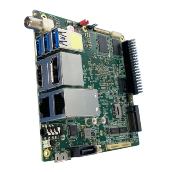
- Page 1 UP Squared Pro Maker Board UPN-APL01 User’s Manual 1 Distributed by www.texim-europe.com...
- Page 2 Copyright Notice This document is copyrighted, 2021. All rights are reserved. The original manufacturer reserves the right to make improvements to the products described in this manual at any time without notice. No part of this manual may be reproduced, copied, translated, or transmitted in any form or by any means without the prior written permission of the original manufacturer.
- Page 3 Acknowledgement All other products’ name or trademarks are properties of their respective owners. Microsoft®, Windows® are registered trademarks of Microsoft Corp. ⚫ Intel®, Pentium®, and Celeron® are registered trademarks of Intel Corporation ⚫ Intel Atom™ is a trademark of Intel Corporation ⚫...
- Page 4 Packing List Before setting up your product, please make sure the following items have been shipped: Item Quantity UPN-APL01 with heatsink (UP Squared Pro Board) ⚫ If any of these items are missing or damaged, please contact your distributor or sales representative immediately.
- Page 5 About this Document This User’s Manual contains all the essential information, such as detailed descriptions and explanations on the product’s hardware and software features (if any), its specifications, dimensions, jumper/connector settings/definitions, and driver installation instructions (if any), to facilitate users in setting up their product. Users may refer to the product page at AAEON.com for the latest version of this document.
- Page 6 Safety Precautions Please read the following safety instructions carefully. It is advised that you keep this manual for future references All cautions and warnings on the device should be noted. Make sure the power source matches the power rating of the device. Position the power cord so that people cannot step on it.
- Page 7 If any of the following situations arises, please the contact our service personnel: Damaged power cord or plug Liquid intrusion to the device iii. Exposure to moisture Device is not working as expected or in a manner as described in this manual The device is dropped or damaged Any obvious signs of damage displayed on the device...
- Page 8 FCC Statement This device complies with Part 15 FCC Rules. Operation is subject to the following two conditions: (1) this device may not cause harmful interference, and (2) this device must accept any interference received including interference that may cause undesired operation.
- Page 9 China RoHS Requirements (CN) 产品中有毒有害物质或元素名称及含量 AAEON Main Board/ Daughter Board/ Backplane 有毒有害物质或元素 部件名称 铅 汞 镉 六价铬 多溴联苯 多溴二苯醚 (Pb) (Hg) (Cd) (Cr(VI)) (PBB) (PBDE) 印刷电路板 ○ ○ ○ ○ ○ ○ 及其电子组件 外部信号 ○ ○ ○ ○ ○ ○ 连接器及线材...
- Page 10 China RoHS Requirement (EN) Poisonous or Hazardous Substances or Elements in Products AAEON Main Board/ Daughter Board/ Backplane Poisonous or Hazardous Substances or Elements Hexavalent Polybrominated Polybrominated Component Lead Mercury Cadmium Chromium Biphenyls Diphenyl Ethers (Pb) (Hg) (Cd) (Cr(VI)) (PBB) (PBDE) PCB &...
-
Page 11: Table Of Contents
Table of Contents Chapter 1 - Product Specifications..................1 Specifications ......................2 Chapter 2 – Hardware Information ..................4 Dimensions ....................... 5 Jumpers and Connectors ..................6 List of Jumpers and Connectors ................8 2.3.1 RTC Battery (CN1) ..................9 2.3.2 M.2 E-Key 2230 Slot (CN7) ................ - Page 12 2.3.21 RS232/ 422/ 485 1x10P Wafer (COM2) ..........23 2.3.22 SIM Card Slot (SIM1) .................. 24 2.3.23 Power Button (SW1) ................... 24 2.3.39 USB3.2 Gen 1 Triple Port (3x Type A) (USB1) ........25 Connector Index ....................26 Chapter 3 – Drivers Installation .................... 28 Driver Download and Installation...............
-
Page 13: Chapter 1 - Product Specifications
Chapter 1 Chapter 1 - Product Specifications Distributed by www.texim-europe.com... -
Page 14: Specifications
Specifications System Processor Intel® Pentium® N4200/ Celeron® N3350/ Atom™ E3950 Processor SoC Graphics Intel® Gen 9 HD, supporting 4K Codec Decode and Encode for HEVC4, H.264, VP8 HDMI x 1 DP x 1 COM port (RS422/RS232/RS485) x 2 Audio Jack x 1 Camera —... - Page 15 System OS Support Microsoft Windows 10 (full), Windows IOT Core Linux: Ubuntu 18.04.5, Ubuntu 20.04.1 Yocto3.1 Operating Temperature With fan: 32°F ~ 140°F (0°C ~ 60°C) With heatsink: 32° ~ 122°F (0°C ~ 50°C) Operation Humidity 0% ~ 90% relative humidity, non-condensing Certification CE/FCC Class A, RoHS Compliant, REACH Distributed by www.texim-europe.com...
-
Page 16: Chapter 2 - Hardware Information
Chapter 2 – Hardware Information Chapter 2 Distributed by www.texim-europe.com... -
Page 17: Dimensions
Dimensions Distributed by www.texim-europe.com... -
Page 18: Jumpers And Connectors
Jumpers and Connectors Top: Distributed by www.texim-europe.com... - Page 19 Bottom: Distributed by www.texim-europe.com...
-
Page 20: List Of Jumpers And Connectors
List of Jumpers and Connectors Please refer to the table below for all of the board’s jumpers that you can configure for your application Label Function RTC Battery Connector M.2 E-Key 2230 Slot SATA Connector CN10 SATA Power CN13 USB3.2 Gen 1 OTG (Type C) Port CN16 USB2.0/ UART 1x10P Wafer CN17... -
Page 21: Rtc Battery (Cn1)
Label Function USB1 USB3.2 Gen 1 Triple Port (3x Type A) 2.3.1 RTC Battery (CN1) Signal VCC_3V3 2.3.2 M.2 E-Key 2230 Slot (CN7) Signal Signal Signal VCC_3V3 USB_D+ VCC_3V3 USB_D- Distributed by www.texim-europe.com... - Page 22 Signal Signal Signal PCIE_TX+ PCIE_TX- PCIE_RX+ PCIE_RX- PCIE_CLK+ PCIE_CLK- SUS_CLK PLT_RST# PCIE_CLKREQ# BT_EN PCIE_WAKE# WIFI_EN VCC_3V3 VCC_3V3 Distributed by www.texim-europe.com...
-
Page 23: Sata Connector (Cn9)
2.3.3 SATA Connector (CN9) Signal Signal Signal SATA_TX+ SATA_TX- SATA_RX- SATA_RX+ 2.3.4 SATA Power (CN10) Signal VCC_5V Distributed by www.texim-europe.com... -
Page 24: Usb3.2 Gen 1 Otg Port (Cn13)
2.3.5 USB3.2 Gen 1 OTG Port (CN13) Signal Signal Signal VCC_5V USB2_D- USB2_D+ USB3_RX- RSB3_RX+ USB3_TX- USB3_TX+ 2.3.6 USB2.0/ UART 1x10P Wafer (CN16) Signal Signal Signal VCC_5V USB2_D6- USB2_D6+ VCC_5V USB2_D7- USB2_D7+ UART_RXD UART_TXD Distributed by www.texim-europe.com... -
Page 25: Fan (Cn17)
2.3.7 FAN (CN17) Signal Signal VCC_5V 2.3.8 Dual LAN Port (CN18) Signal Signal LAN1_MDI0+ LAN1_MDI0- LAN1_MDI1+ LAN1_MDI1- LAN1_MDI2+ LAN1_MDI2- LAN1_MDI3+ LAN1_MDI3- R10A LAN1_ACTLED- LAN1_ACTLED+ LAN1_LINK100# LAN1_LINK1000# LAN2_MDI0+ LAN2_MDI0- LAN2_MDI1+ LAN2_MDI1- LAN2_MDI2+ LAN2_MDI2- LAN2_MDI3+ LAN2_MDI3- R10B Distributed by www.texim-europe.com... -
Page 26: 40-Pin Gpio (Hat40) (Cn20)
Signal Signal LAN2_ACTLED- LAN2_ACTLED+ LAN2_LINK100# LAN2_LINK1000# 2.3.9 40-pin GPIO (HAT40) (CN20) Signal 3.3V I2C2_DAT/ GPIO1 I2C2_CLK/ GPIO2 GPIO3 UART_TX/ GPIO16 ANALOG_DATA1/ SPI3_TXD† UART_RX/ GPIO17 UART_RTS/ GPIO4 I2S6_BCLK/ GPIO18 ANALOG_DATA2† GPIO5 ANALOG_DATA3/ SPI3_RXD† GPIO6 PWM3/ GPIO19 ANALOG_DATA4/ SPI3_CS2† 3.3V I2S2_SDO/ GPIO20 SPI1_TX/ GPIO7 SPI1_R/ GPIO8 I2S2_BCLK/ GPIO21... -
Page 27: Cpld And Bios Update (Cn22)
Signal GPIO11 SPI3_CS1† I2S2_SDI/ GPIO12 PWM0/ GPIO25 PWM1 / GPIO13 I2S6_SYNC/ GPIO14 UART_CTS/ GPIO26 I2S2_SYNC/ GPIO15 I2S6_SDI/ GPIO27 I2S6_SDO / GPIO28 †Note: Apollo Lake-I processors only. 2.3.10 CPLD and BIOS update (CN22) Signal Signal Signal JTAG_TCK JTAG_TDO VCC_1V8 JTAG_TMS SPI_CS SPI_CLK SPI_MISO JTAG_TDI... -
Page 28: Dc Jack (Cn23)
2.3.11 DC Jack (CN23) Signal Signal Signal DC_IN 2.3.12 HDMI/ DP Dual Port (CN24) Signal Signal DP_TXP0 DP_TXN0 DP_TXP1 DP_TXN1 DP_TXP2 DP_TXN2 DP_CLK+ DP_CLK- CONFIG1 CONFIG2 DP_AUX_P DP_AUX_N DP_HPD VCC_3V3 HDMI_TXP0 Distributed by www.texim-europe.com... -
Page 29: Edp Connector (Cn26)
Signal Signal HDMI_TXN0 HDMI_TXP1 HDMI_TXN1 HDMI_TXP2 HDMI_TXN2 HDMI_CLK+ HDMI_CLK- HDMI1_CEC DDC_CLK DDC_DATA VCC_5V HDMI_HPD 2.3.13 eDP Connector (CN26) Signal Signal VCC_3V3 VCC_3V3 EDP_TXN_2 EDP_TXP_2 EDP_TXN_1 EDP_TXP_1 EDP_TXN_0 EDP_TXP_0 EDP_TXN_3 EDP_TXP_3 EDP_AUXN EDP_AUXP Distributed by www.texim-europe.com... -
Page 30: B-Key 3042/3052 Slot (Cn27)
Signal Signal BKLT_CTRL BKLT_EN EDP_HPD VCC_12V/VCC_24V VCC_12V/VCC_24V VCC_12V/VCC_24V VCC_12V/VCC_24V 2.3.14 M.2 B-Key 3042/3052 Slot (CN27) Signal Signal VCC_3V3 VCC_3V3 FULL_CARD_POWER_OFF# USB2_D5+ W_DISABLE#1 USB2_D5- Distributed by www.texim-europe.com... - Page 31 Signal Signal USB3_RX- UIM_RST USB3_RX+ UIM_CLK UIM_DAT USB3_TX- UIM_PWR USB3_TX+ PLT_RST#(3V3) PCIE_CLK- PCIE_WAKE# Distributed by www.texim-europe.com...
-
Page 32: M-Key 2280 Slot (Cn28)
Signal Signal PLT_RST#(1V8) SUSCLK VCC_3V3 VCC_3V3 VCC_3V3 2.3.15 M.2 M-Key 2280 Slot (CN28) Signal Signal Signal VCC_3V3 VCC_3V3 VCC_3V3 VCC_3V3 VCC_3V3 VCC_3V3 DEVSLP Distributed by www.texim-europe.com... -
Page 33: Audio Jack (Cn29)
Signal Signal Signal PCIE_RX- PCIE_RX+ PCIE_TX- PCIE_TX- PLT_RST# PCIE_CLKREQ# PCIE_CLK- PCIE_WAKE# PCIE_CLK+ SUSCLK VCC_3V3 VCC_3V3 VCC_3V3 2.3.16 Audio Jack (CN29) Signal Signal Signal MIC_L/R FRONT_R AUDIO-JD FRONT_L Distributed by www.texim-europe.com... -
Page 34: Pwr Select 12V (Cn31)
2.3.17 PWR Select 12V (CN31) Signal 2.3.18 PWR Select 24V (CN32) Signal 2.3.19 Front Panel Connector (CN34) Signal Signal RESET POWER S/W +3.3V Distributed by www.texim-europe.com... -
Page 35: Rs232/ 422/ 485 1X10P Wafer (Com1)
2.3.20 RS232/ 422/ 485 1x10P Wafer (COM1) Signal Signal DCD / RS422TX- / S485- RX / RS422TX+ / RS485+ TX / RS422RX+ DTR / RS422RX- DSRA RTSA CTSA 2.3.21 RS232/ 422/ 485 1x10P Wafer (COM2) Signal Signal DCD / RS422TX- / S485- RX / RS422TX+ / RS485+ TX / RS422RX+ DTR / RS422RX-... -
Page 36: Sim Card Slot (Sim1)
2.3.22 SIM Card Slot (SIM1) Signal Signal Signal UIM_PWR UIM_RST UIM_CLK UIM_VPP UIM_DAT 2.3.23 Power Button (SW1) Switch Position Function SW1 1 (default) SW1 0 Power ON Distributed by www.texim-europe.com... -
Page 37: Usb3.2 Gen 1 Triple Port (3X Type A) (Usb1)
2.3.39 USB3.2 Gen 1 Triple Port (3x Type A) (USB1) Signal Signal Signal VCC_5V USB2_D1- USB2_D1+ USB3_RX1- USB3_RX1+ USB3_TX1- USB3_TX1+ VCC_5V USB2_D2- USB2_D2+ USB3_RX2- USB3_RX2+ USB3_TX2- USB3_TX2+ VCC_5V USB2_D3- USB2_D3+ USB3_RX3- USB3_RX3+ USB3_TX3- USB3_TX3+ Distributed by www.texim-europe.com... -
Page 38: Connector Index
Connector Index Label Function Connector Type (TF)WAFER BOX.2P .180D(M).DIP .1.25mm.PINREX.712-71-02TW01 (TF)M.2 Key-E Slot.H=4.0mm E-KEY conn.75P .90D(F).BLACK.SMD.FOXCONN.AS0BC21-S40BE-7H SATA (TF)SATA CONNECTOR.7P .180D(M).SMT.TechBest.007-01-00757 CONN SATA (TF)WAFER CN10 POWER BOX.2P .180D(M).DIP .2.0mm.w/LOCK.PINREX.721-81-02TW00 USB3 CN13 (TF)Micro USB 3.0 Conn..10P .90D(M).SMD.B-type.ATTEND.209E-BE01 USB3 (TF)USB CONN..DIP .USB3.0 TRIPLE USB1 TRPLE PORT.27P .90D.FEMALE.Standard.Type... - Page 39 Label Function Connector Type SEL(24V) Front CN34 (TF)Wafer Box.6P .180D.(M).SMD.1.0mm.w/ CAP .CATCH.1204-700-06SMR Panel (TF)Nano SIM Card Connector.3P*2.Hinge SIM1 SIM card Type.SMD.SUNFUN.SMHN-SO1(01T) RS232 / 422 / 485 COM1 (TF)Wafer Box.10P .180D(M).SMD.1.0mm.w/ CAP .CATCH.1204-700-10SMR 1x10P Wafer RS232 / 422 / 485 COM2 (TF)Wafer Box.10P .180D(M).SMD.1.0mm.w/ CAP .CATCH.1204-700-10SMR 1x10P Wafer...
-
Page 40: Chapter 3 - Drivers Installation
Chapter 3 Chapter 3 – Drivers Installation Distributed by www.texim-europe.com... -
Page 41: Driver Download And Installation
Driver Download and Installation Please access https://www.up-community.org and go to the Downloads section > UP Squared to find the relevant drivers. Unknown Device Troubleshooting After installing the drivers on Windows 10, you may see five unknown devices in the device manager. Follow the steps below to resolve each issue: Multimedia Audio Controller Go into the device BIOS Settings. - Page 42 PCI Device (8086&DEV_5AC8), Unknown Device (AANT0F01), and VEN_AANT&DEV_1280 Go into the device BIOS Settings. Navigate to the Boot menu. Change OS Selection to “Windows. ” Distributed by www.texim-europe.com...
- Page 43 PCI Device: The unknown PCI device is the PWM signal. It is provided directly from the Apollo Lake chipset, but Intel has not released a Windows driver for this device. This PCI device is not available for Windows 10, it is only supported by Linux. VEN_AANT&DEV_1280: This is the ADC for Linux, there is no Windows driver.
-
Page 44: Appendix A - Up Framework Sdk Installation
Appendix A Appendix A – UP Framework SDK Installation Distributed by www.texim-europe.com... -
Page 45: Introduction
Introduction This section provides instructions for the installation of the UP Framework SDK. Instructions are provided for Windows 10 and Windows IoT Core. You can download the latest version of UP Framework SDK from the UP community: https://downloads.up-community.org/download/up-sdk-for-windows-10-and-windows-iot/ A.2 Installation for Windows 10 Step 1 Locate the downloaded file UpFrameworkSetup.msi and run the installer. - Page 46 Step 2 Select the installation folder. Default destination path is C:\Program Files(x86)\AAEON\ You may also choose to install the UP Framework SDK for all users or only the current user. Press “Next” to continue installation. Step 3 Press “Next” to confirm the installation. Distributed by www.texim-europe.com...
- Page 47 Step 4 Press “Close” to exit once setup is complete. Distributed by www.texim-europe.com...
-
Page 48: A.3 Installation For Windows Iot Core
A.3 Installation for Windows IoT Core Before you begin, make sure you have downloaded and installed the latest version of the Windows IoT Core image from the UP community. Installation requires using a connected PC with the UP Framework SDK software downloaded and saved. - Page 49 Step 2 Download the UP Framework SDK to your PC and unzip the files. Open PowerShell as an Administrator. Run the command RemoteInstallation.ps1 to install the UP Framework SDK. Enter the IP address of the UP IoT Core device when prompted. Distributed by www.texim-europe.com...
-
Page 50: Appendix B - Cables And Connectors
Appendix B Appendix B – Cables and Connectors Distributed by www.texim-europe.com... -
Page 51: Cables And Connectors
Cables and Connectors This table provides detailed information about the cables and connectors used by the UP Squared Pro (UPN-APL01). If you have any questions about the configuration of your board, please contact your AAEON sales representative. Mating Label Connector PN Function Description Mating Cable Description Cable PN Lithium... - Page 52 Mating Label Connector PN Function Description Mating Cable Description Cable PN CN32 1653002100 PWR SEL(24V) CN34 1655906033 Front Panel SIM1 1654900693 SIM card (TF)COM Cable.D-SUB RS232 / 422 / 485 1x10P COM1 1655901000 1701100180 9P(M).10P .1.0mm Wafer Housing.15cm (TF)COM Cable.D-SUB RS232 / 422 / 485 1x10P COM2 1655901000...
- Page 53 Contact details The Netherlands Belgium UK & Ireland Elektrostraat 17 Zuiderlaan 14 bus 10 St. Mary’s House, Church Lane NL-7483 PG Haaksbergen B-1731 Zellik Carlton Le Moorland Lincoln LN5 9HS +31 (0)53 573 33 33 +32 (0)2 462 01 00 +44 (0)1522 789 555 F: +31 (0)53 573 33 30 +32 (0)2 462 01 25...