Table of Contents
Advertisement
Advertisement
Table of Contents

Related Manuals for Asus A55M-A Series


Summary of Contents for Asus A55M-A Series
- Page 1 A55M-A Series • A55M-A • A55M-A/USB3...
- Page 2 Product warranty or service will not be extended if: (1) the product is repaired, modified or altered, unless such repair, modification of alteration is authorized in writing by ASUS; or (2) the serial number of the product is defaced or missing.
-
Page 3: Table Of Contents
Contents Safety information ...................... vi About this guide ......................vii A55M-A Series specifications summary ..............ix Package contents ....................... xi Product introduction Special features .................... 1-1 1.1.1 Product highlights ................1-1 1.1.2 ASUS DIGI+ VRM ................1-1 1.1.3 ASUS Exclusive Features ............... 1-2 Before you proceed .................. - Page 4 Managing and updating your BIOS ............. 2-1 2.1.1 ASUS Update utility ................ 2-1 2.1.2 ASUS EZ Flash 2 ................2-2 2.1.3 ASUS CrashFree BIOS 3 utility ............2-3 2.1.4 ASUS BIOS Updater ............... 2-4 BIOS setup program ..................2-6 Main menu ....................2-10 2.3.1 System Language [English] ............
- Page 5 2.7.11 Boot Option Priorities ..............2-29 2.7.12 Boot Override ................2-29 Tools menu ....................2-30 2.8.1 ASUS EZ Flash 2 Utility ..............2-30 2.8.2 ASUS SPD Information ..............2-30 2.8.3 ASUS O.C. Profile ................. 2-30 Exit menu ....................2-31 Appendices Notices ........................
-
Page 6: Safety Information
Safety information Electrical safety • To prevent electrical shock hazard, disconnect the power cable from the electrical outlet before relocating the system. • When adding or removing devices to or from the system, ensure that the power cables for the devices are unplugged before the signal cables are connected. If possible, disconnect all power cables from the existing system before you add a device. -
Page 7: About This Guide
Refer to the following sources for additional information and for product and software updates. ASUS websites The ASUS website provides updated information on ASUS hardware and software products. Refer to the ASUS contact information. Optional documentation Your product package may include optional documentation, such as warranty flyers, that may have been added by your dealer. -
Page 8: Conventions Used In This Guide
Conventions used in this guide To ensure that you perform certain tasks properly, take note of the following symbols used throughout this manual. DANGER/WARNING: Information to prevent injury to yourself when trying to complete a task. CAUTION: Information to prevent damage to the components when trying to complete a task IMPORTANT: Instructions that you MUST follow to complete a task . -
Page 9: A55M-A Series Specifications Summary
Supports AMD Memory Profile (AMP) memory • The maximum 32GB memory capacity can be supported with 16GB or above DIMMs. ASUS will update the memory QVL once the DIMMs are available in the market. • Refer to www.asus.com for the latest Memory QVL (Qualified Vendors List). - Page 10 1 x DVI port 1 x D-Sub output port 1 x LAN (RJ-45) port 2 x USB 3.0 ports and 2 x USB 2.0/1.1 ports (A55M-A/USB3 only) 4 x USB 2.0/1.1 ports (A55M-A only) 8-channel audio I/O ports (3-jack) Internal I/O 2 x USB 2.0/1.1 connectors support additional 4 USB 2.0/1.1 ports...
-
Page 11: Package Contents
1 x I/O Shield User Guide Support DVD • A55M-A Series motherboards include A55M-A and A55M-A/USB3 models. The package contents vary from models. • If any of the above items is damaged or missing, contact your retailer. • The illustrated items above are for reference only. Actual product specifications may... -
Page 13: Product Introduction
Engineered and tested to assure unmitigated performance, ASUS A55 boards with DIGI+ VRM remain efficient and accurate for reliable performance in every scenario. -
Page 14: Asus Exclusive Features
ASUS EZ Flash 2 ASUS EZ Flash 2 is a user-friendly utility that allows you to update the BIOS without using a bootable floppy disk or an OS-based utility. Chapter 1: Product introduction... -
Page 15: Asus Mylogo2
Turn your favorite photos into 256-color boot logos to personalize your system. ASUS CrashFree BIOS 3 ASUS CrashFree BIOS 3 allows you to restore a corrupted BIOS file from a USB storage device that contains the BIOS file. USB 3.0 Boost (A55M-A/USB3 only) With USB 3.0 Boost technology, a USB device’s transmission speed is significantly... -
Page 16: Before You Proceed
ON, in sleep mode, or in soft-off mode. This is a reminder that you should shut down the system and unplug the power cable before removing or plugging in any motherboard component. The illustration below shows the location of the onboard LED. SB_PWR A55M-A/USB3 Standby Power Powered Off A55M-A/USB3 Onboard LED Chapter 1: Product introduction... -
Page 17: Motherboard Overview
Place six screws into the holes indicated by circles to secure the motherboard to the chassis. DO NOT overtighten the screws! Doing so can damage the motherboard. Place this side towards the rear of the chassis. A55M-A/USB3 ASUS A55M-A Series... -
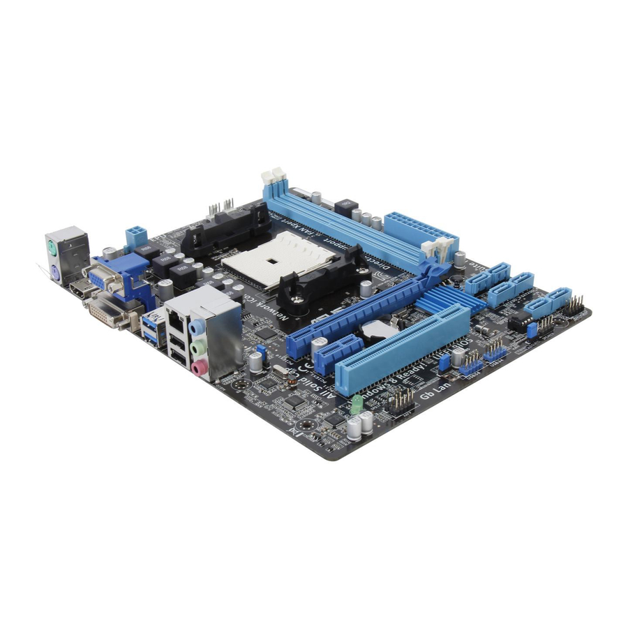
Page 18: Motherboard Layout
1.3.3 Motherboard layout A55M-A Series motherboards include A55M-A and A55M-A/USB3 models. The package contents vary between models. The layout illustrations in this user guide are for A55M- A/USB3 only. 18.8cm(7.4in) CPU_FAN CHA_FAN KBMS DIGI ATX12V +VRM HDMI USB1112 LAN1_USB12 1042... -
Page 19: Layout Contents
Ensure that you use a APU designed for the FM2 socket. The APU fits in only one correct orientation. DO NOT force the APU into the socket to prevent bending the pins and damaging the APU! A55M-A/USB3 A55M-A/USB3 CPU socket FM2 ASUS A55M-A Series... -
Page 20: Apu Installation
1.4.1 APU installation Chapter 1: Product introduction... -
Page 21: Apu Heatsink And Fan Assembly Installation
1.4.2 APU heatsink and fan assembly installation Apply the Thermal Interface Material to the APU heatsink and APU before you install the heatsink and fan if necessary. To install the APU heatsink and fan assembly ASUS A55M-A Series... - Page 22 To uninstall the APU heatsink and fan assembly Chapter 1: Product introduction 1-10...
-
Page 23: System Memory
DDR2 DIMM socket. DDR3 modules are developed for better performance with less power consumption. The figure illustrates the location of the DDR3 DIMM sockets: Channel Sockets Channel A DIMM_A1 A55M-A/USB3 Channel B DIMM_B1 A55M-A/USB3 240-pin DDR3 DIMM sockets ASUS A55M-A Series 1-11... -
Page 24: Memory Configurations
• The maximum 32GB memory capacity can be supported with 16GB or above DIMMs. ASUS will update the memory QVL once the DIMMs are available in the market. • The default memory operation frequency is dependent on its Serial Presence Detect (SPD), which is the standard way of accessing information from a memory module. - Page 25 (2 x 2GB) 12GB KINGSTON KHX1600C9D3K3/12GX(XMP) 9-9-9-27 1.65V (3x4GB) 12GB KINGSTON KHX1600C9D3T1BK3/12GX(XMP) 9-9-9-27 1.65V (3x4GB) 16GB KINGSTON KHX1600C9D3K4/16GX(XMP) 1.65V (4GBx4) 16GB KINGSTON KHX1600C10D3B1K2/16G 1.5V (8GBx2) 16GB KINGSTON KHX16C9K2/16 1.5V (8GBx2) KINGSTON KHX1600C9AD3/2G 1.65V KINGSTON KVR1600D3N11/2G-ES D1288JPNDPLD9U 11-11-11-28 1.35V-1.5V ASUS A55M-A Series 1-13...
- Page 26 DDR3 1600 MHz capability DIMM socket support Chip Vendors Part No. Size Chip No. Timing Voltage (optional) Brand 1DIMM 2DIMMs KHX1600C7D3K2/4GX(XMP) 4GB KINGSTON 1.65V (2x2GB) KHX1600C8D3K2/4GX(XMP) 4GB KINGSTON 1.65V (2x2GB) KHX1600C8D3T1K2/4GX KINGSTON 1.65V (XMP) (2x2GB) KHX1600C9D3K2/4GX(XMP) 4GB KINGSTON 1.65V (2x2GB) KHX1600C9D3LK2/4GX KINGSTON (XMP)
- Page 27 23EY4587MB3H11503M 9-9-9-24 1.5V ASint SLZ302G08-EDJ1C Asint SLZ302G08-DJ1C ASint SLA302G08-EDJ1C Asint SLA302G08-DJ1C ASint SLB304G08-EDJ1B Asint SLB304G08-DJ1B Elixir M2F2G64CB88B7N-CG Elixir N2CB2G80BN-CG Elixir M2F2G64CB88D7N-CG Elixir N2CB2G80DN-CG Elixir M2F2G64CB88G7N-CG Elixir N2CB2G80GN-CG Elixir M2F4G64CB8HB5N-CG Elixir N2CB2G80BN-CG Elixir M2F4G64CB8HD5N-CG 4GB Elixir N2CB2G80DN-CG ASUS A55M-A Series 1-15...
-
Page 28: Channel Memory Configuration
1 DIMM: Supports one module inserted into any slot as Single-channel memory configuration. • 2 DIMMs: Supports two modules inserted into both the blue slots as one pair of Dual- channel memory configuration. Visit the ASUS website at www.asus.com for the latest QVL. Chapter 1: Product introduction 1-16... -
Page 29: Installing A Dimm
1.5.3 Installing a DIMM To remove a DIMM ASUS A55M-A Series 1-17... -
Page 30: Expansion Slots
Expansion slots In the future, you may need to install expansion cards. The following sub-sections describe the slots and the expansion cards that they support. Unplug the power cord before adding or removing expansion cards. Failure to do so may cause you physical injury and damage motherboard components. -
Page 31: Irq Assignments For This Motherboard
– shared – – – – On Chip USB EHCI 1/2/3 – shared – – – – – – On Chip USB EHCI 1/2/3/4 shared ASM1042 USB3.0 controller – – shared – – – – – ASUS A55M-A Series 1-19... -
Page 32: Jumpers
A55M-A/USB3 Normal Clear RTC (Default) A55M-A/USB3 Clear RTC RAM To erase the RTC RAM: Turn OFF the computer and unplug the power cord. Move the jumper cap from pins 1-2 (default) to pins 2-3. Keep the cap on pins 2-3 for about 5~10 seconds, then move the cap back to pins 1-2. - Page 33 This feature requires an ATX power supply that can supply at least 1A on the +5VSB lead, and a corresponding setting in the BIOS. KB_USBPWB A55M-A/USB3 +5VSB (Default) A55M-A/USB3 Keyboard and USB device wake up ASUS A55M-A Series 1-21...
-
Page 34: Connectors
Connectors 1.8.1 Rear panel ports PS/2 Mouse port (green). This port is for a PS/2 mouse. Video Graphics Adapter (VGA) port. This 15-pin port is for a VGA monitor or other VGA-compatible devices. LAN (RJ-45) port. This port allows Gigabit connection to a Local Area Network (LAN) through a network hub. -
Page 35: Internal Connectors
USB 3.0 ports 11 and 12 (A55M-A/USB3 only). These two 4-pin Universal Serial Bus (USB) ports are for connecting USB 3.0 devices. USB 2.0 ports 11 and 12 (A55M-A only). These two 4-pin Universal Serial Bus (USB) ports are for USB 2.0/1.1 devices. - Page 36 The system may become unstable or may not boot up if the power is inadequate. • If you are uncertain about the minimum power supply requirement for your system, refer to the Recommended Power Supply Wattage Calculator at http://support.asus. com/PowerSupplyCalculator/PSCalculator.aspx?SLanguage=en-us for details. Chapter 1: Product introduction 1-24...
- Page 37 SATA3G_1 SATA3G_2 A55M-A/USB3 A55M-A/USB3 SATA 3.0Gb/s connectors • These connectors are set to AHCI mode by default. If you intend to create a Serial ATA RAID set using these connectors, set the type of the SATA connectors in the BIOS to [RAID].
-
Page 38: System Panel Connector
PIN 1 A55M-A/USB3 +HD_LED RESET A55M-A/USB3 System panel connector • System power LED (2-pin PLED) This 2-pin connector is for the system power LED. Connect the chassis power LED cable to this connector. The system power LED lights up when you turn on the system power, and blinks when the system is in sleep mode. -
Page 39: Digital Audio Connector
A55M-A/USB3 HD-audio-compliant Legacy AC’97 pin definition compliant definition A55M-A/USB3 Front panel audio connector • We recommend that you connect a high-definition front panel audio module to this connector to avail of the motherboard high-definition audio capability. • If you want to connect a high definition front panel audio module to this connector, set the Front Panel Type item in the BIOS to [HD]. - Page 40 480Mbps connection speed. USB56 USB34 A55M-A/USB3 PIN 1 PIN 1 A55M-A/USB3 USB2.0 connectors Never connect a 1394 cable to the USB connectors. Doing so will damage the motherboard! The USB 2.0 module is purchased separately. Chapter 1: Product introduction 1-28...
-
Page 41: Software Support
The contents of the Support DVD are subject to change at any time without notice. Visit the ASUS website at www.asus.com for updates. To run the Support DVD Place the Support DVD into the optical drive. - Page 42 Chapter 1: Product introduction 1-30...
-
Page 43: Bios Information
BIOS in the future. Copy the original motherboard BIOS using the ASUS Update utility. 2.1.1 ASUS Update utility The ASUS Update is a utility that allows you to manage, save, and update the motherboard BIOS in Windows environment. ®... -
Page 44: Asus Ez Flash 2
Follow the onscreen instructions to complete the updating process. 2.1.2 ASUS EZ Flash 2 The ASUS EZ Flash 2 feature allows you to update the BIOS without using an OS-based utility. Before you start using this utility, download the latest BIOS file from the ASUS website at www.asus.com. -
Page 45: Asus Crashfree Bios 3 Utility
2.1.3 ASUS CrashFree BIOS 3 utility The ASUS CrashFree BIOS 3 is an auto recovery tool that allows you to restore the BIOS file when it fails or gets corrupted during the updating process. You can restore a corrupted BIOS file using the motherboard support DVD or a USB flash drive that contains the updated BIOS file. -
Page 46: Asus Bios Updater
2.1.4 ASUS BIOS Updater The ASUS BIOS Updater allows you to update BIOS in DOS environment. This utility also allows you to copy the current BIOS file that you can use as a backup when the BIOS fails or gets corrupted during the updating process. -
Page 47: Updating The Bios File
0202 VER: Unknown DATE: 01/13/2013 DATE: Unknown PATH: A55M-A-USB3.CAP 8390656 2012-07-13 17:30:48 Note [Enter] Select or Load [Tab] Switch [V] Drive Info [Up/Down/Home/End] Move [B] Backup [Esc] Exit Press <Tab> to switch between screen fields and use the <Up/Down/Home/End> keys to select the BIOS file and press <Enter>. -
Page 48: Bios Setup Program
BIOS menu screen The BIOS setup program can be used under two modes: EZ Mode and Advanced Mode. You can change modes from the Exit menu or from the Exit/Advanced Mode button in the EZ Mode/Advanced Mode screen. ASUS A55M-A Series... - Page 49 EZ Mode By default, the EZ Mode screen appears when you enter the BIOS setup program. The EZ Mode provides you an overview of the basic system information, and allows you to select the display language, system performance mode and boot device priority. To access the Advanced Mode, click Exit/Advanced Mode, then select Advanced Mode or press F7 hot key for the advanced BIOS settings.
-
Page 50: Advanced Mode
The Advanced Mode provides advanced options for experienced end-users to configure the BIOS settings. The figure below shows an example of the Advanced Mode. Refer to the following sections for the detailed configurations. To access the EZ Mode, click Exit, then select ASUS EZ Mode. Back button Menu items... -
Page 51: Menu Items
Menu items The highlighted item on the menu bar displays the specific items for that menu. For example, selecting Main shows the Main menu items. The other items (Ai Tweaker, Advanced, Monitor, Boot, Tool, and Exit) on the menu bar have their respective menu items. -
Page 52: Main Menu
RAM to clear the BIOS password. See section 1.7 Jumpers for information on how to erase the RTC RAM. The Administrator or User Password items on top of the screen show the default • Not Installed. After you set a password, these items show Installed. 2-10 ASUS A55M-A Series... -
Page 53: Administrator Password
Administrator Password If you have set an administrator password, we recommend that you enter the administrator password for accessing the system. Otherwise, you might be able to see or change only selected fields in the BIOS setup program. To set an administrator password: Select the Administrator Password item and press <Enter>. -
Page 54: Ai Tweaker Menu
Be cautious when changing the settings of the Ai Tweaker menu items. Incorrect field values can cause the system to malfunction. The configuration options for this section vary depending on the CPU and DIMM model you installed on the motherboard. Scroll down to display the following items: 2-12 ASUS A55M-A Series... -
Page 55: Ai Overclock Tuner [Auto]
Target CPU Speed : xxxxMHz Displays the current CPU speed. Target DRAM Speed : xxxxMHz Displays the current DRAM speed. 2.4.1 Ai Overclock Tuner [Auto] Allows you to select the CPU overclocking options to achieve the desired CPU internal frequency. Select any of these preset overclocking configuration options: [Auto] Loads the optimal settings for the system. -
Page 56: Dram Timing Control
The values of the CPU Offset Voltage, VDDNB Offset Voltage, DRAM Voltage, and • SB 1.1V Voltage items are labeled in a different color, indicating the risk levels of high voltage settings. • The system may need a better cooling system to work properly under high voltage settings. 2-14 ASUS A55M-A Series... -
Page 57: Digi+ Vrm
Reducing phase number under light system loading to increase VRM efficiency. [Standard] Proceeds phase control depending on the CPU loading. [Optimized] Loads the ASUS optimized phase tuning profile. [Extreme] Proceeds the full phase mode. [Manual Adjustment] Allows manual adjustment. -
Page 58: Advanced Menu
Enables or disables the AMD PowerNow function. Configuration options: [Enabled] [Disabled] NX Mode [Enabled] Enables or disables the No-execute page protection function. Configuration options: [Enabled] [Disabled] SVM [Enabled] Enables or disables CPU virtualization. Configuration options: [Disabled] [Enabled] 2-16 ASUS A55M-A Series... - Page 59 CPB Mode [Auto] Disables the CPB (Core Performance Boost) mode or set it to [Auto] for automatic configuration. Configuration options: [Disabled] [Auto] C6 Mode [Enabled] Enables or disables C6 mode. Configuration options: [Enabled] [Disabled] IOMMU [Disabled] Set this item to [Enabled] to show IOMMU Mode. Configuration options: [Enabled] [Disabled] Bank Interleaving [Enabled] Enables or disables Bank Interleaving.
-
Page 60: Sata Configuration
S.M.A.R.T. Status Check [Enabled] S.M.A.R.T. (Self-Monitoring, Analysis and Reporting Technology) is a monitor system. When read/write of your hard disk errors occur, this feature allows the hard disk to report warning messages during the POST. Configuration options: [Enabled] [Disabled] 2-18 ASUS A55M-A Series... -
Page 61: Usb Configuration
Allows the system to detect the presence of USB devices at startup. If detected, the USB controller legacy mode is enabled. If no USB device is detected, the legacy USB support is disabled. Legacy USB3.0 Support [Enabled] (A55M-A/USB3 only) [Enabled] Enables the support for USB 3.0 devices on legacy operating systems (OS). -
Page 62: Onboard Devices Configuration
Enables the onboard USB 3.0 controller. [Disabled] Disables the controller. Asmedia USB 3.0 Battery Charging Support [Disabled] (A55M-A/USB3 only) This item appears only when the Asmedia USB 3.0 Controller item is set to [Enabled]. [Enabled] Enables the Asmedia USB 3.0 battery charging function. -
Page 63: Apm
2.5.6 Restore AC Power Loss [Power Off] [Power On] The system goes into on state after an AC power loss. [Power Off] The system goes into off state after an AC power loss. [Last State] The system goes into either off or on state, whatever the system state was before the AC power loss. -
Page 64: Network Stack
[Enabled] Ipv6 PXE Support [Enabled] This item appears only when you set the Network Stack item to [Enabled]. When this item is disabled, the IPV6 PXE boot option will not be created. Configuration options: [Disabled] [Enabled] 2-22 ASUS A55M-A Series... -
Page 65: Monitor Menu
Monitor menu The Monitor menu displays the system temperature/power status, and allows you to change the fan settings. 2.6.1 CPU Temperature / MB Temperature [xxxºC/xxxºF] The onboard hardware monitor automatically detects and displays the CPU and motherboard temperatures. Select Ignore if you do not wish to display the detected temperatures. 2.6.2 CPU / Chassis fan Speed [xxxx RPM] or [Ignore] / [N/A]... -
Page 66: Anti Surge Support [Auto]
40% to 100%. When the CPU temperature is under the lower limit, the CPU fan will operate at the minimum duty cycle. 2.6.5 Anti Surge Support [Auto] This item allows you to enable or disable the Anti Surge function. Configuration options: [Auto] [Disabled] [Enabled] 2-24 ASUS A55M-A Series... -
Page 67: Boot Menu
Boot menu The Boot menu items allow you to change the system boot options. Scroll down to display the following items: Chapter 2: BIOS information 2-25... -
Page 68: Fast Boot [Enabled]
[Disabled] Disables the full screen logo display feature. Set this item to [Enabled] to use the ASUS MyLogo 2™ feature. Post Report [5 sec] This item appears only when the Full Screen Logo item is set to [Disabled] and allows you to set the waiting time for the system to display the post report. -
Page 69: Post Delay Time [3 Sec]
2.7.3 Post Delay Time [3 sec] Allows you to set the POST Report wait time. This configuration only functions in Normal Boot mode. Configuration options: [0 sec] [1 sec] [2 sec] [3 sec] [4 sec] [5 sec] [6 sec] [7 sec] [8 sec] [9 sec] [10 sec] 2.7.4 Bootup NumLock State [On]... -
Page 70: Csm Parameters
Manage the Secure Boot Keys (PK, KEK, DB, DBX) Install default Secure Boot Keys Configuration options: [Yes] [No] Platform Key (PK) Load PK from File Configuration options: [Ok] Copy PK to File Configuration options: [Ok] Delete the PK Configuration options: [Yes] [No] 2-28 ASUS A55M-A Series... -
Page 71: Boot Option Priorities
• To select the boot device during system startup, press <F8> when ASUS Logo appears. • To access Windows OS in Safe Mode, press <F8> after POST. -
Page 72: Tools Menu
<Enter> to display the submenu. 2.8.1 ASUS EZ Flash 2 Utility Allows you to run ASUS EZ Flash 2. Press [Enter] to launch the ASUS EZ Flash 2 screen. For more details, see section 2.1.2 ASUS EZ Flash 2. 2.8.2... -
Page 73: Exit Menu
This option allows you to exit the Setup program without saving your changes. When you select this option or if you press <Esc>, a confirmation window appears. Select Yes to discard changes and exit. ASUS EZ Mode This option allows you to enter the EZ Mode screen. Launch EFI Shell from filesystem device This option allows you to attempt to launch the UEFI Shell application (shellx64.efi) from one... - Page 74 2-32 ASUS A55M-A Series...
-
Page 75: Appendices
: (1) cet appareil ne doit pas provoquer d’interférences et (2) cet appareil doit accepter toute interférence, y compris celles susceptibles de provoquer un fonctionnement non souhaité de l’appareil. ASUS A55-M A Series... -
Page 76: Canadian Department Of Communications Statement
ASUS Recycling/Takeback Services ASUS recycling and takeback programs come from our commitment to the highest standards for protecting our environment. We believe in providing solutions for you to be able to responsibly recycle our products, batteries, other components as well as the packaging materials. -
Page 77: Asus Contact Information
+1-812-282-3777 +1-510-608-4555 Web site usa.asus.com Technical Support Telephone +1-812-282-2787 Support fax +1-812-284-0883 Online support support.asus.com ASUS COMPUTER GmbH (Germany and Austria) Address Harkort Str. 21-23, D-40880 Ratingen, Germany +49-2102-959911 Web site www.asus.de Online contact www.asus.de/sales Technical Support Telephone +49-1805-010923* Support Fax... - Page 78 Appendices...