Table of Contents
Advertisement
Quick Links
Advertisement
Table of Contents

Related Manuals for Asus A7V333-X


Summary of Contents for Asus A7V333-X
- Page 1 A7V333-X User Guide...
- Page 2 Product warranty or service will not be extended if: (1) the product is repaired, modified or altered, unless such repair, modification of alteration is authorized in writing by ASUS; or (2) the serial number of the product is defaced or missing.
-
Page 3: Table Of Contents
1.10 Connectors ..............1-13 Chapter 2 - BIOS Information ............2-1 2.1 Managing and updating your BIOS ......2-2 2.1.1 Using ASUS EZFLASH to update the BIOS....2-2 2.1.2 Using ASUS AFLASH to update the BIOS....2-4 Updating BIOS procedures........2-5 2.2 BIOS Setup Program ........... -
Page 4: Contents
3.2.1 Running the support CD ..........3.2.2 Software drivers and installation menus ....3.3 Software Information........... 3.3.1 ASUS Update ............. 3.3.2 ASUS PC Probe ............Starting ASUS PC Probe ........Using ASUS PC Probe ......... ASUS PC Probe Task Bar Icon ....... 3-9... -
Page 5: Fcc/Cdc Statements
FCC/CDC statements Federal Communications Commission Statement This device complies with FCC Rules Part 15. Operation is subject to the following two conditions: • This device may not cause harmful interference, and • This device must accept any interference received including interference that may cause undesired operation. -
Page 6: Safety Information
Safety information Electrical safety • To prevent electrical shock hazard, disconnect the power cable from the electrical outlet before relocating the system. • When adding or removing devices to or from the system, ensure that the power cables for the devices are unplugged before the signal cables are connected. -
Page 7: Conventions Used In This Guide
1. ASUS Websites The ASUS websites worldwide provide updated information on ASUS hardware and software products. The ASUS websites are listed in the ASUS Contact Information on page viii. 2. Optional Documentation Your product package may include optional documentation, such as warranty flyers, that may have been added by your dealer. -
Page 8: Asus Contact Information
Technical Support Support Fax: +1-510-608-4555 General Support: +1-502-995-0883 Web Site: www.asus.com Support Email: tsd@asus.com ASUS COMPUTER GmbH (Germany and Austria) Address: Harkortstr. 25, 40880 Ratingen, BRD, Germany General Fax: +49-2102-442066 General Email: sales@asuscom.de (for marketing requests only) Technical Support Support Hotline:... -
Page 9: Specifications Summary
ASUS MyLogo ASUS EZ Flash ASUS Q-Fan Power Loss Restart ASUS JumperFree SFS (Stepless Frequency Selection) ASUS C.O.P. (CPU Overheating Protection) Back Panel I/O Ports 1 x Parallel 2 x Serial 1 x PS/2 Keyboard 1 x PS/2 Mouse 1 x Audio I/O (on audio model only) 4 x USB 2.0... - Page 10 A7V333-X specifications summary BIOS features 2Mb Flash ROM, ASUS JumperFree, Award BIOS, DMI2.0, PnP, WfM2.0, BIOS 2.3, ASUS EZ Flash, ASUS MyLogo, TCAV (Trend Chip Away Virus) Industry standard PCI 2.2, USB 2.0. Manageability WfM2.0, DMI2.0, WOR, WOL, Chassis Intrusion Form Factor ATX form factor: 12 in x 9.6 in...
- Page 11 Chapter 1 This chapter gives information about the ASUS A7V333-X motherboard that came with the system.This chapter includes the motherboard layout, jumper settings, and connector locations. ASUS A7V333-X Motherboard...
-
Page 12: Welcome
A processors. This motherboard is loaded with value-added features for guaranteed consumer satisfaction. Unique ASUS features such as ASUS C.O.P., ASUS EZ Flash, ASUS MyLogo and more are included to ensure the best user experience and value in a motherboard. For future upgrades or system reconfiguration, this chapter provides technical information about the motherboard. -
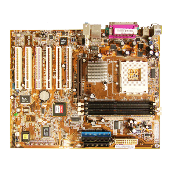
Page 13: Motherboard Components
Motherboard components ASUS A7V333-X Motherboard... - Page 14 IDE controller, up to six USB 2.0 ports, PS/2 keyboard and mouse port, LPC Super I/O interface, AC’97 interface,10/100Mb LAN and PCI 2.2 interface.. ASUS ASIC. This chip performs multiple system functions that include hardware and system voltage monitoring among others. Flash ROM. This 2Mb firmware contains the programmable BIOS program.
- Page 15 USB 2.0 ports. These two 4-pin Universal Serial Bus 2.0 (USB 2.0) ports are available for connecting USB devices such as a mouse and PDA. PS/2 keyboard port. This purple 6-pin connector is for a PS/2 keyboard. ASUS A7V333-X Motherboard...
-
Page 16: Motherboard Layout
AUX1 Below:Mic In Accelerated Graphics Port (AGP4X) FP_AUDIO1 PCI1 Chip PCI2 VT8235 Chipset Audio Codec PCI3 ASUS ASIC CR2032 3V Lithium Cell A7V333-X ® with Hardware CMOS Power Monitor CLRTC1 PCI4 PCI5 2Mbit Firmware CHASSIS1 PCI6 SB_PWR1 CHA_FAN1 USBPWR_56 PANEL1... -
Page 17: Before You Proceed
Central Processing Unit (CPU) The motherboard provides a Socket A (462) for CPU installation. AMD processors offer gigahertz speeds to support all the latest computing platforms and applications. The A7V333-X supports Athlon XP/Athlon and Duron processors. CPU NOTCH... -
Page 18: System Memory
3. Visit ASUS website (www.asus.com) for latest DDR333 Qualified Vendor List. Expansion slots The A7V333-X motherboard has six (6) expansion slots. The following sub- sections describe the slots and the expansion cards that they support. 1.8.1 Configuring an expansion card After physically installing the expansion card, configure the card by adjusting the software settings. -
Page 19: Standard Interrupt Assignments
This motherboard has an Accelerated Graphics Port (AGP) slot that supports +1.5V AGP 4X cards. Note the notches on the card golden fingers to ensure that they fit the AGP slot on your motherboard. ® A7V333-X Keyed for 1.5v A7V333-X Accelerated Graphics Port (AGP) ASUS A7V333-X Motherboard... -
Page 20: Jumpers
Setting to a very high core voltage may cause permanent damage to the CPU. It is recommended that you keep the default setting (Disable). OVER_VOLT1 OVERVOLT OVERVOLT ENABLE DISABLE (Default) ® A7V333-X A7V333-X CPU Over Voltage Setting 1-10 Chapter 1: Motherboard Information... - Page 21 The total current consumed must NOT exceed the power supply capability (+5VSB) whether under normal condition or in sleep mode. USBPWR_12 USBPWR_34 +5VSB (Default) USBPWR_56 A7V333-X ® +5VSB (Default) A7V333-X USB Device Wake Up ASUS A7V333-X Motherboard 1-11...
- Page 22 5. Plug the power cord and turn ON the computer. 6. Hold down the <Del> key during the boot process and enter BIOS setup to re-enter data. CLRTC1 A7V333-X ® Clear CMOS Normal (Default) A7V333-X Clear RTC RAM 1-12 Chapter 1: Motherboard Information...
-
Page 23: Connectors
For UltraDMA/133/100/66 IDE devices, use an 80-conductor IDE cable. NOTE: Orient the red markings (usually zigzag) on the IDE ribbon cable to PIN 1. A7V333-X ® PIN 1 A7V333-X IDE Connectors ASUS A7V333-X Motherboard 1-13... - Page 24 ® NOTE: Orient the red markings on the floppy ribbon cable to PIN 1. A7V333-X Floppy Disk Drive Connector ATX power connectors (20-pin ATXPWR1) These connectors connect to an ATX 12V power supply. The plugs from the power supply are designed to fit these connectors in only one orientation. Find the proper orientation and push down firmly until the connectors completely fit.
- Page 25 USB_56 ® A7V333-X (Blue) A7V333-X USB 2.0 Header The USB module is not included in the package. 5. GAME/MIDI connector (16-1 pin GAME1) (on Audio model only) This connector supports a GAME/MIDI module. If your package came with the optional USB 2.0/GAME module, connect the GAME/MIDI cable to this connector.
- Page 26 CHA_FAN1 ® A7V333-X A7V333-X 12-Volt Fan Connectors Do not forget to connect the fan cables to the fan connectors. Lack of sufficient air flow within the system may damage the motherboard components. These are not jumpers! DO NOT place jumper caps on the fan connectors! 7.
- Page 27 BLINE_OUT_L ® A7V333-X A7V333-X Front Panel Audio Connector Hard disk connector (2-pin IDELED1) This 2-pin connector connects to the front panel HD LED and lights up on every read/write activity of any of the disc drives connected to the primary or secondary IDE slots.
- Page 28 These connectors allow you to receive stereo audio input from sound sources such as a CD-ROM, TV tuner, or MPEG card. AUX1 (White) CD1 (Black) ® A7V333-X A7V333-X Internal Audio Connectors 12. System panel connector (20-pin PANEL1) This connector accommodates several system front panel functions. Keyboard Lock Speaker Connector...
- Page 29 ON and SLEEP, or ON and SOFT OFF, depending on the BIOS or OS settings. Pressing the power switch while in the ON mode for more than 4 seconds turns the system OFF. ASUS A7V333-X Motherboard 1-19...
- Page 30 Chapter 2 This chapter gives information about the ASUS A7V333-X Basic Input/Output System (BIOS).This chapter includes updating the BIOS using the ASUS AFLASH BIOS that is bundled with the support CD. ASUS A7V333-X Motherboard...
-
Page 31: Chapter 2: Bios Information
2.1.1 Using ASUS EZ Flash to update the BIOS The ASUS EZ Flash feature allows you to easily update the BIOS without having to go through the long process of booting from a diskette and using a DOS-based utility. - Page 32 5. At the prompt, “Please Enter File Name for NEW BIOS: _”, type in the BIOS file name that you downloaded from the ASUS website, then press <Enter>. EZ Flash will automatically access drive A to look for the file name that you typed.
-
Page 33: Using Asus Aflash To Update The Bios
2.1.2 Using AFLASH to update the BIOS Creating a bootable disk AFLASH.EXE is a Flash Memory Writer utility that updates the BIOS by uploading a new BIOS file to the programmable flash ROM on the motherboard. This file works only in DOS mode. To determine the BIOS version of your motherboard, check the last four numbers of the code displayed on the upper left-hand corner of your screen during bootup. -
Page 34: Updating The Bios
Careless updating may result to more problems with the motherboard! 1. Download an updated ASUS BIOS file from the Internet (WWW or FTP) (see ASUS CONTACT INFORMATION on page x for details) and save to the boot floppy disk you created earlier. - Page 35 Just repeat the process, and if the problem persists, load the original BIOS file you saved to the boot disk. If the Flash Memory Writer utility is not able to successfully update a complete BIOS file, call the ASUS service center for support. Chapter 2: BIOS Information...
-
Page 36: Bios Setup Program
EXIT Use this menu to exit the current menu or to exit the Setup program. To access the menu bar items, press the right or left arrow key on the keyboard until the desired item is highlighted. ASUS A7V333-X Motherboard... -
Page 37: Legend Bar
2.2.2 Legend bar At the bottom of the Setup screen is a legend bar. The keys in the legend bar allow you to navigate through the various setup menus. The following table lists the keys found in the legend bar with their corresponding functions. Navigation Key(s) Function Description <F1>... -
Page 38: Main Menu
Valid values for month, day, and year are Month: (1 to 12), Day: (1 to 31), Year: (up to 2099). Use the <Tab> or <Shift> + <Tab> keys to move between the month, day, and year fields. ASUS A7V333-X Motherboard... - Page 39 Legacy Diskette A; Legacy Diskette B [1.44M, 3.5 in.] Sets the type of floppy drive installed. Configuration options: [None] [360K, 5.25 in.] [1.2M , 5.25 in.] [720K , 3.5 in.] [1.44M, 3.5 in.] [2.88M, 3.5 in.] Floppy 3 Mode Support [Disabled] This is required to support older Japanese floppy drives.
-
Page 40: Primary And Secondary Master/Slave
[CD-ROM] - for IDE CD-ROM drives [LS-120] - for LS-120 compatible floppy disk drives [ZIP] - for ZIP-compatible disk drives [MO] - for IDE magneto optical disk drives [Other ATAPI Device] - for IDE devices not listed here ASUS A7V333-X Motherboard 2-11... - Page 41 After making your selections on this sub-menu, press the <Esc> key to return to the Main menu. When the Main menu appears, the hard disk drive field displays the size for the hard disk drive that you configured. Translation Method [LBA] Select the hard disk drive type in this field.
-
Page 42: Keyboard Features
Options range from 6 to 30 characters per second. Configuration options: [6/Sec] [8/Sec] [10/Sec] [12/Sec] [15/Sec] [20/Sec] [24/Sec] [30/Sec] Keyboard Auto-Repeat Delay [1/4 Sec] This field sets the time interval for displaying the first and second characters. Configuration options: [1/4 Sec] [1/2 Sec] [3/4 Sec] [1 Sec] ASUS A7V333-X Motherboard 2-13... -
Page 43: Advanced Menu
Advanced Menu CPU Speed This field allows you to select the internal frequency of the CPU. Select [Manual] if you want to make changes to the next two fields. Note that the system memory can only operate at a frequency higher than or equal to the CPU FSB frequency. CPU Frequency Multiple This field displays frequency multiple value between the CPU’s internal frequency (CPU speed) and external frequency. -
Page 44: Chip Configuration
When using OS/2 operating systems with installed DRAM of greater than 64MB, you need to set this option to [Enabled]. Otherwise, leave to the default setting [Disabled]. Configuration options: [Disabled] [Enabled] 2.4.1 Chip Configuration (Use the scroll bar to view other items.) ASUS A7V333-X Motherboard 2-15... - Page 45 SDRAM Configuration [By SPD] This parameter allows you to set the optimal timings for items 2–5, depending on the memory modules that you are using. The default setting is [By SPD], which configures items 2–5 by reading the contents in the SPD (Serial Presence Detect) device.
- Page 46 You can also set both channels to [Disabled]. Configuration options: [Both] [Primary] [Secondary] [Disabled] DRAM Burst Length Configuration options: [4] [Auto] S2K Bus Driving Strength Configuration options: [Auto] [Manual] S2K Strobe P Control Configuration options: [0][1][2][3][4][5][6][7][8][9][A][B][C][D][E][F] S2K Strobe N Control Configuration options: [0][1][2][3][4][5][6][7][8][9][A][B][C][D][E][F] ASUS A7V333-X Motherboard 2-17...
-
Page 47: I/O Device Configuration
2.4.2 I/O Device Configuration Onboard FDC Swap A & B [No Swap] This field sets option to switch driver letter assignments. Configuration options: [No Swap] [Swap AB] Floppy Disk Access Control [R/W] When set to [Read Only], this parameter protects files from being copied to floppy disks by allowing reads from, but not writes to, the floppy disk. -
Page 48: Pci Configuration
This field allows you to select the primary graphics card. Configuration options: [PCI VGA Card] [AGP VGA Card] Onboard LAN Boot ROM [Disabled] This field allows you to enable or disable the option ROM in the onboard LAN chipset. Configuration options: [Disabled] [Enabled] ASUS A7V333-X Motherboard 2-19... -
Page 49: Pci Irq Resource Exclusion
2.4.3.1 PCI IRQ Resource Exclusion IRQ XX Reserved [No/ICU] These fields indicate whether or not the displayed IRQ for each field is being used by a legacy (non-PnP) ISA card. The setting [No/ICU] for an IRQ field indicates that you are using the ISA Configuration Utility (ICU), and that this particular IRQ is NOT required by a legacy ISA card. - Page 50 When set to [Auto] the ASIC will shut down the system to protect the CPU if the temperature reachers the Over Temperature Shut Down setting value. It is recommended to use default [Auto] setting to protect your CPU. Configuration options: [Auto] [Manual] ASUS A7V333-X Motherboard 2-21...
-
Page 51: Power-Up Control
2.5.1 Power Up Control AC PWR Loss Restart [Disabled] This allows you to set whether or not to reboot the system after power interruptions. [Disabled] leaves your system off while [Enabled] reboots the system. [Previous State] sets the system back to the state it was before the power interruption. -
Page 52: Hardware Monitor
Q-Fan Control [Disabled] This item allows you to enable or disable the ASUS Q-Fan feature that smartly adjusts the fan speeds for more efficient system operation. When this field is set to [Enabled], the Fan Speed Ratio and Speed Up/Down Response Time items appear to allow selection of the appropriate fan speeds and the corresponding response time. -
Page 53: Boot Menu
Boot Menu Boot Sequence The Boot menu allows you to select four types of boot devices using the up and down arrow keys. By using the <+> or <Space> key, you can promote devices and by using the <-> key, you can demote devices. Promotion or demotion of devices alters the priority which the system uses to boot the system. -
Page 54: Exit Menu
Setup. Select Exit from the menu bar to display the following menu. Pressing <Esc> does not immediately exit this menu. Select one of the options from this menu or <F10> from the legend bar to exit. ASUS A7V333-X Motherboard 2-25... -
Page 55: Load Setup Defaults
Exit & Saving Changes Once you are finished making your selections, choose this option from the Exit menu to ensure the values you selected are saved to the CMOS RAM. The CMOS RAM is sustained by an onboard backup battery and stays on even when the PC is turned off. - Page 56 Chapter 3 This chapter helps you power up your system and install drivers and utilities that came with the support CD. ASUS A7V333-X Motherboard...
-
Page 57: Chapter 3: Starting-Up
The support CD that came with the motherboard contains useful software and several utility drivers that enhance the motherboard features. The contents of the support CD are subject to change at any time without notice. Visit the ASUS website for updates. 3.2.1 Running the support CD To begin using the support CD, simply insert the CD into your CD-ROM drive. -
Page 58: Software Drivers And Installation Menus
- VIA INF Driver 1.70a Avance AC’97 Audio Driver and Applications This item installs the Avance AC’97 audio driver and applications. USB 2.0 Driver This item installs the USB 2.0 driver. Some menu items appear only to specific operating system versions. ASUS A7V333-X Motherboard... - Page 59 Browse Support CD Click this item to display the support CD contents. Technical support request form This item displays for print the ASUS technical support form. File List Click this item to view the file list of support software available.
-
Page 60: Software Information
3.3 Software information 3.3.1 ASUS Update The ASUS Update utility allows you to update the motherboard BIOS and drivers. This utility requires an Internet connection either through a network or an Internet Service Provider (ISP). Follow these steps to use the ASUS Update. -
Page 61: Asus Pc Probe
DMI Explorer. Starting ASUS PC Probe When ASUS PC Probe starts, a splash screen appears allowing you to select whether to show the screen again when you open PC Probe or not. To bypass this startup screen, clear the Show up in next execution check box. -
Page 62: Using Asus Pc Probe
Using ASUS PC Probe Monitoring Temperature Warning Threshold Adjustment (Move the slider up to increase the threshold level or down to decrease the threshold level) Monitor Summary Temperature Monitor Shows a summary of the items Shows the PC temperature (for being monitored. - Page 63 Settings Lets you set threshold levels and polling intervals or refresh times of the PC’s temperature, fan rotation, and voltages. CPU Cooling System Setup Lets you select when to enable software CPU cooling. When When CPU Overheated is selected, the CPU cooling system is enabled whenever the CPU temperature reaches the threshold value.
-
Page 64: Asus Pc Probe Task Bar Icon
Utility NOTE: This feature is currently unavailable. ASUS PC Probe Task Bar Icon Right clicking the PC Probe icon brings up a menu to open or exit ASUS PC Probe and pause or resume all system monitoring.