Advertisement
Available languages
Available languages
Quick Links
G e n e r a l i n f o r m a t i o n :
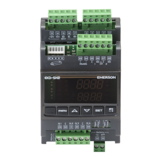
EXD-SH1/2 are stand alone superheat and or temperature controllers. EXD-SH1 is
intended for operation of one bipolar valve CX/EX/FX valve whereas EXD-SH2 is
designed for operation of two independent bipolar CX/EX/FX valves.
A table of the available application possibilities is listed below:
Controller
Circuit 1: Main function
EXD-SH1
Superheat or temperature control
EXD-SH2
Superheat or temperature control
Notes:
It is possible to use only circuit 1 from EXD-SH2. In this case, the circuit 2 must
be disabled (C2 parameter) and the sensors and the valve for the second circuit
are not needed.
ModBus communication is described in a Technical Bulletin and it is not
covered by this document.
T e c h n i c a l d a t a :
Power supply
24VAC/DC +10%/-10% 50/60HZ,
Power consumption
EXD-SH1: 25VA
Plug-in connector
Removable screw terminals wire size 0.14...1.5 mm
Protection class
IP00
ECN-N... (temperature range down to -45°C)
Temperature sensors
ECN-Z... (temperature range down to -80°C ultra
low temperature)
Allowable
operating/surrounding
0...+55°C
temperature
Maximum cable distance
50 cm
between EXD-SH and
AWG 18 wire size ( 1mm
EXD-PM
Pressure sensors
PT5 or ratiometric probes
Output alarm relay current
Resistive Load 24 V AC/DC, 1 A
rating
Inductive Load 24 V AC/DC, 0.5 A
Contact is closed:
During alarm condition
Contact is open:
During normal operation and supply power OFF
Stepper motor output
Valves: EX4...8, CX4...7 and FX5...9
Mounting
For standard DIN rail
Marking
D i m e n s i o n s [ m m ] :
S a f e t y i n s t r u c t i o n s :
• Read operating instructions thoroughly. Failure to comply can result in device
failure, system damage or personal injury.
• It is intended for use by persons having the appropriate knowledge and skill.
• Before installation or service disconnect all voltages from system and device.
• Do not operate system before all cable connections are completed.
• Do not apply voltage to the controller before completion of wiring.
• Entire electrical connections have to comply with local regulations.
• Inputs are not isolated, potential free contacts needed to be used.
• Disposal: Electrical and electronic waste must NOT be disposed of with other
commercial waste. Instead, it is the user responsibility to pass it to a
designated collection point for the safe recycling of Waste Electrical and
Electronic Equipment (WEEE
information, contact your local environmental recycling center.
Emerson Climate Technologies GmbH
Am Borsigturm 31 I 13507 Berlin I Germany
Operating Instructions
EXD-SH1/2 Controller for EX/CX/FX with
ModBus communication capability
Circuit 2: Main function
Superheat Control
EXD-SH2: 50VA
2
)
directive 2002/95/EC).
For further
www.emersonclimate.eu
T e m p e r a t u r e s e t t i n g i n n o r m a l s e ns e
(Controller function as temperature controller)
Valve opening
100%
0%
2
1tAL
T e m p e r a t u r e s e t t i n g i n r e v e r s e s e n s e
(Controller function as temperature controller)
Valve opening
100%
0%
1tAL
E l e c t r i c a l c o n n e c t i o n a n d w i r i n g :
• Refer to the electrical wiring diagram for electrical connections.
• Note: Keep controller and sensor wiring well separated from supply power
cables. Minimum recommended distance 30mm.
• When connecting the wires of the EXV-M... (electrical plug of valves)
consider the color coding as follows:
EXV-M...: WH: White;
• The digital input DI1 (EXD-SH1/SH2) and DI2 (EXD-SH2) are the interfaces
between EXD-SH1/2 and upper level system controller if the Modbus
communication has not been used. The external digital inputs must be free of
potential (dry contact) and shall be operated in function system's
compressor/demand.
Operating condition
Compressor starts/run
Compressor stops
Note: Connecting any EXD-SH1/2 inputs to the supply voltage will permanently
damage the EXD-SH1/2.
Date: 26.04.2017
%
1tbd
1tst
%
1tbd
1tst/
BK: Black; BN: Brown; BL: Blue
Digital input status
External contact to be closed (Start)
External contact to be open (Stop)
EXD-SH12_OI_ML_R03_865917.docx
Temperature
1tAH
Temperature
1tAH
Advertisement

Related Manuals for Emerson EXD-SH1


Summary of Contents for Emerson EXD-SH1
- Page 1 EXV-M…: WH: White; BK: Black; BN: Brown; BL: Blue • The digital input DI1 (EXD-SH1/SH2) and DI2 (EXD-SH2) are the interfaces between EXD-SH1/2 and upper level system controller if the Modbus S a f e t y i n s t r u c t i o n s : communication has not been used.
-
Page 2: Pressure Transmitter
Operating Instructions EXD-SH1/2 Controller for EX/CX/FX with ModBus communication capability Wiring options: UPS (ECP-024) /Supercap (EXD-PM) UPS for up to two controllers EXV-M… EXV-M… Cable & Plug Cable & Plug 24 V One supercap for one EXD-SH1 EXD-M… Cable & Plug... -
Page 3: Temperature Control
• Press both the buttons for more than 5 seconds. • Apply supply voltage 24V to EXD-SH1/2 while the digital input (DI1/DI2) is open. • A flashing “0” is displayed in upper and “PAS” at lower. The valve will be driven to close position. - Page 4 SH1/2 is designed under consideration of European safety standards and directives Low pressure alarm cut-in [bar] -0.5 for none flammable refrigerants. The use of EXD-SH1/2 with R32 is for Freeze alarm delay mode systems/regions which it does not require consideration of additional safety standards 0 = disabled;...
- Page 5 50% and 100% higher. This false • Temperature control function is possible only with EX4-8 series valves. If other signal leads to improper operation of EXD-SH1/2 controller and can lead to valves are used, then the ACF alarm will be displayed.
- Page 6 BK: Schwarz; BN: Braun; BL: Blau • Die Digitaleingänge DI1 (EXD-SH1/SH2) und DI2 (EXD-SH2) sind die Schnittstellen zwischen EXD-SH1/2 und dem übergeordnetem Systemregler, S i c h e r h e i t s h i n w e i s e : wenn keine Modbus Kommunikation eingesetzt wird.
- Page 7 Klasse II zu verwenden. Die 24V Leitungen dürfen nicht geerdet werden. Wir Drucktransmitter empfehlen die Verwendung jeweils separater EMERSON Transformatoren für EXD-SH1/2 Regler und die Regler anderer Hersteller, weil unter Umständen über die Erdleitungen Kurzschlüsse entstehen können. • Wenn EXD-PM angeschlossen ist, ist es notwendig, dass der EXD-SH-Regler und die EXD-PM-Kondensatoren eigene Transformatoren haben.
- Page 8 • Sobald die wichtigsten Parameter eingestellt und gespeichert sind, ist der Regler • Diese Abfolge kann für alle einzustellenden Parameter wiederholt werden. EXD-SH1/2 fertig für die Inbetriebnahme. Alle anderen Parameter könne auch Um die neuen Werte dauerhaft zu speichern und den Einstellmodus zu während des Betriebes oder im Stand-By Modus verändert werden.
- Page 9 EXD-SH1/2 ist nach den Richtlinien für nicht brennbare Kältemittel entwickelt. Rückstellung Niederdruckalarm [bar] -0.5 Die Verwendung des EXD-SH1/2 für R32 ist nur in Regionen zulässig in denen keine Frostschutzalarm Regelkreis 1 zusätzlichen Sicherheitsvorschriften für R32 bestehen bzw. anzuwenden sind. 0 = aus; 1 = ein - autom. Rückstellung; 2 = ein - Handrückstellung Grenzwert Frostschutzalarm [°C]...
- Page 10 Signal geliefert bekommen (50%-100% höher als der entsprechende Druck- Ventile gewählt sind erscheint ein Alarm. wert). Diese Störung kann zur Fehlfunktion des EXD-SH1/2 und zu System-/ • Ratiometrische Drucktransmitter können nicht mit R744 gewählt werden. Verdichterschäden führen. Für den Fall ist EMERSON nicht verantwortlich.
-
Page 11: Instructions De Service
Les EXD-SH1/2 sont des contrôleurs de surchauffe et/ou de température autonomes. (Fonctionnement en contrôle de température) L’EXD-SH1 est destiné à être utilisé avec une vanne bipolaire des séries CX/EX/FX, Ouverture vanne % tandis que l’EXD-SH2 est conçu pour fonctionner avec deux vannes indépendantes des séries CX/EX/FX. - Page 12 à la terre les lignes 24VAC. Nous recommandons l’utilisation de Capteur de pression transformateurs séparés pour l’EXD-SH1/2 et pour un régulateur tiers afin d’éviter les possibles interférences ou les masses dans l’alimentation. • Si un EXD-PM est connecté, Il est impératif d’avoir deux transformateurs séparés pour l’EXD-SH1/2 et l’EXD-PM.
- Page 13 • Presser simultanément les boutons pendant plus de 5 seconds. • Appliquer la tension d’alimentation 24V à l’EXD-SH1/2 lorsque le contact • Un “0”clignotant est affiché en haut et “PAS” en bas. d’entrée numérique est ouvert (DI1/DI2). La vanne doit de fermer.
- Page 14 17.7 *) Notes for R32: R32 est classifié en Europe comme faiblement inflammable. Les Tempo d’alarme basse pression [s] EXD-SH1/2 sont conçus selon les normes et standards de sécurité Européen pour les Réarmament alarme basse pression [bar] -0.5 réfrigérants non inflammables. Leur utilisation avec du R32 est donc limitée aux Mode délai alarme givrage...
- Page 15 EXD SH1/2 pouvant • La fonction contrôle de température est possible uniquement avec la série EX4-8. entrainer des dommages au compresseur. Emerson n’est pas responsable dans Si d’autres vannes sont sélectionnées, l’alarme ACF sera affichée.
- Page 16 • Wej cia cyfrowe DI1 (EXD-SH1/SH2) oraz DI2 (EXD-SH2) s powi zane • Produkt przeznaczony jest do u ytku przez osoby posiadaj ce odpowiedni pomi dzy EXD-SH1/2 i sterownikiem nadrz dnym je eli komunkacja Modbus nie wiedz i kwalifikacje.
- Page 17 • Do zasilania 24 VAC nalezy stosowa transformator klasy II. Nie uziemia linii 24 VAC. Rekomendujemy stosowanie oddzielnych transformatorów do Przetworniki ci nienia zasilania sterowników EXD-SH1/2 oraz do zasilania innych sterowników w systemie w celu unikni cia ewentualnych zakłóce w zasilaniu lub problemów 4-20mA z uziemieniem.
- Page 18 • Powtórzy procedur dla kolejnych parametrów, je eli istnieje taka potrzeba. • Po ustawieniu i zapisie podstawowych parametrów sterownik EXD-SH1/2 jest Wyj cie z zapisem nowych ustawie : gotowy do pracy. Wszystkie pozostałe parametry mog by modyfikowane w dowolnym momencie pracy lub postoju systemu.
- Page 19 Stosowanie 0 = nie aktywny; 1 = aktywny auto-reset; 2 = aktywny reset r czny EXD-SH1/2 z R32 jest mo liwe w systemach / regionach, w których nie jest Wył czenie alarmu zamarzania [°C] wymagane rozpatrywanie standardów bezpiecze stwa jak dla czynników palnych.
- Page 20 ACF. Fałszywy sygnał prowadzi do nieprawidłowej pracy sterownika EXD-SH1/2 I • Proporcjonalne przetworniki ci nienia nie mog by stosowane z czynnikiem mo e spowodowa uszkodzenie spr arki lub system. EMERSON nie ponosi R744. odpowiedzialno ci w takich przypadkach.
-
Page 21: Istruzioni Di Installazione
• L’ingresso digitale DI1 (EXD-SH1/SH2) e DI2 (EXD-SH2) sono l’interfaccia tra causare il danneggiamento dell’apparecchiatura, dell’impianto o il ferimento EXD-SH1/2 e il controllore di sistema nel caso in cui non venga utilizzata la del personale. comunicazione Modbus. Gli ingressi digitali esterni devono essere privi di •... - Page 22 24VAC. Suggeriamo di utilizzare un trasformatore per ogni controllo Trasduttore di pressione EXD-SH1/2 e per trasformatori di terze parti per evitare possibili interfernze nell’alimentazione o nella messa a terra. • Se EXD-PM è connesso, è obbligatorio utilizzare singoli trasformatori per EXD-SH…...
- Page 23 5 secondi. valvola. • Uno “0” lampeggiante viene mostrato in alto e “PAS” in basso. • Alimentare a 24V il controllo EXD-SH1/2 con l’ingresso digitale (DI1/DI2) • Premere fino a quando viene mostrato “12”; (password). aperto. La valvola si porterà in posizione di chiusura.
- Page 24 17.7 *) Note per R32: R32 è classificato come refrigerante a bassa infiammabilità in Europa. EXD-SH1/2 è progettato in accordo alle normative di sicurezza europee per Ritardo allarme bassa pressione [s] refrigeranti non infiammabili. L’utilizzo del controllo EXD-SH1/2 con R32 può...
- Page 25 50% e 100% più alto. Questo segnale errato comporta un • La funzione di controllo della temperatura è disponibile solo per le valvole EX4-8. funzionamento improprio del controllo EXD-SH1/2 e può causare danni al Se vengono usate altri tipi di valvole, appare l’allarme ACF.
- Page 26 ; BL: • • DI1 (EXD-SH1/SH2) DI2 (EXD-SH2) EXD-SH1/2 • Modbus « » • / 24 • EXD-SH1/2 • EXD-SH1/2. • • « » Emerson Climate Technologies GmbH www.emersonclimate.eu Am Borsigturm 31 I 13507 Berlin I Germany Date: 26.04.2017 EXD-SH12_OI_ML_R03_865917.docx...
- Page 27 EXD-SH1/2 EX/CX/FX ModBus (ECP-024) / (EXD-PM) EXV-M… EXV-M… EXD-SH1 EXD-M… 24 B EXD-SH2 (ECN-N…/ECN-Z…) • EXD-SH1/2 ( / 4-20 • EXD-PM, EXD-SH… EXD-PM. 1 (EXD-SH1/SH2) 14-17 EXV-M… 2 (EXD-SH2) 19-22 EXV-M… AC/DC RS485 ( +/-) 1 (C,NO) – AC/DC 2 (C, NO) –...
- Page 28 / psig) – MOP. ; 1 = • ; 1 = EXD-SH2). • [K/F] OPEn [°C/°F] tASP / psig] PEuA [°C/°F] tEuA : (0A) Emerson Climate Technologies GmbH www.emersonclimate.eu Am Borsigturm 31 I 13507 Berlin I Germany Date: 26.04.2017 EXD-SH12_OI_ML_R03_865917.docx...
- Page 29 1tAL [°C] R744 1tdL R407A R407F 1tAH [°C] 1tdH R1234ze R448A 0 = ECN-Nxx (-45°C…+40°C); 1 = ECN-Z60 ( -80°C…-40°C) R23 R449A R450A R513A Emerson Climate Technologies GmbH www.emersonclimate.eu Am Borsigturm 31 I 13507 Berlin I Germany Date: 26.04.2017 EXD-SH12_OI_ML_R03_865917.docx...
- Page 30 0.5 - 4.5 ). R450A, R513A, R1234ze. 50% - 100%. • EX4-8. EXD-SH1/2 ACF. • EMERSON R744. , . . EXD- SH... ut. ( Emerson Climate Technologies GmbH www.emersonclimate.eu Am Borsigturm 31 I 13507 Berlin I Germany Date: 26.04.2017 EXD-SH12_OI_ML_R03_865917.docx...