Advertisement
Quick Links
DELTA
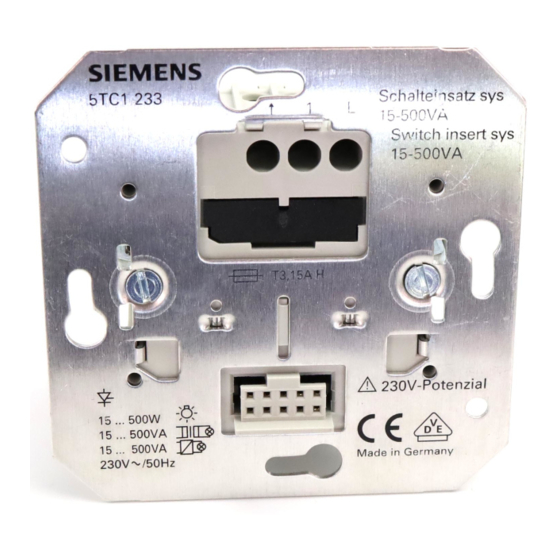
Schalteinsatz sys 15-500VA
Switch insert sys 15-500VA
Bedien- und Montageanleitung
Operating and mounting instructions
Stand:
August 2004
As at:
August 2004
A
1
L
A1
5TC1 233
A2
211
Produkt- und Funktionsbeschreibung
Der Schalteinsatz sys 5TC1 233 ist ein Unterputzgerät zum
Schalten von verschiedenen elektrischen Verbrauchern. Es
können Glühlampen, Hochvolt-Halogenlampen und Niedervolt-
Halogenlampen mit vorgeschalteten konventionellen oder
5TC1 233
elektronischen Transformatoren angesteuert werden.
Der Schalteinsatz sys besitzt eine 2-Leiter-Anschlusstechnik
und schaltet die angeschlossene Last über ein Relais.
Die Bedienung bzw. Ansteuerung des Schalteinsatzes sys er-
folgt über die Taste wave UP 210 (Funk), welche die für die
Schaltvorgänge notwendigen Befehle über die spezifische
230V-Anwenderschnittstelle (230V-AST) an den Schalteinsatz
sys weitergibt. Zur weiteren Bedienung können über den An-
schluss für Nebenstellen beliebig viele konventionelle Taster
angeschlossen werden.
Bedienung
Die Bedienung des Schalteinsatzes sys erfolgt über die aufge-
steckte Taste wave UP 210. Diese kann OBEN, UNTEN oder
MITTIG (d.h. OBEN und UNTEN gleichzeitig) betätigt werden.
Schalten:
Betätigung OBEN
Betätigung UNTEN
Betätigung MITTIG
Parametriermodus Funk (Betätigung länger 10s):
Betätigung MITTIG
Konventioneller Taster am Anschluss für Nebenstellen:
Bei Betätigung wird die angeschlossene Last UM geschaltet.
HINWEIS:
Die genaue Funktionalität bei Verwendung der Taste wave
UP
210
kann
der
Montageanleitung entnommen werden.
Anschlussbeispiel
Bild A
A1 Lastanschluss
A2 Anschluss für Nebenstellen
A3 Außenleiteranschluss
A4 Sicherungshalter inkl. Sicherung und Ersatzsicherung
A5 Anwenderschnittstelle (230V-AST)
Technische Daten
Spannungsversorgung
erfolgt über 230V-Netzanschluss (2-Leitertechnik)
Bemessungsspannung: AC 230V, 50Hz
Sicherung gegen Kurzschluss
Der Schalteinsatz sys ist bei Kurzschluss durch eine Feinsiche-
A3
rung (T3,15A - Schaltvermögen "H") abgesichert. Nach Besei-
tigung des Kurzschlusses (Spannungswiederkehr) muss die
ausgelöste Feinsicherung ersetzt werden. Eine Ersatzsiche-
rung steht im Sicherungshalter zur Verfügung.
A4
Lastanschluss:
• Anzahl: 1
• Bemessungsspannung: AC 230V, 50Hz
A5
• Bemessungslast :
-
Glühlampenlast:
-
Konventionelle Trafos:
(Ausnahme: Ringkerntrafos
-
Elektronische Trafos:
VORSICHT:
• Konventionelle Trafos dürfen nur verwendet werden, wenn
diese eine thermische Sicherung besitzen.
• Bei Einsatz eines konventionellen Ringkerntrafos ist darauf
zu achten, dass dessen Einschaltstromstoß nicht zum
Auslösen der Feinsicherung (T3,15A H) führt.
• Der Schalteinsatz sys kann nicht mit Energiesparlampen,
Leuchtstofflampen mit KVG/EVG und einigen nicht
dimmbaren elektronischen Trafos betrieben werden.
Verhalten bei Netzspannungswiederkehr
Der Schalteinsatz sys nimmt nach Netzspannungswiederkehr
den Schaltzustand vor Netzspannungsausfall an.
Anschlüsse
Die Anschlüsse für den Schalteinsatz sys bestehen aus drei
Schraubklemmen.
Es sind folgende Leiter-/ querschnitte zulässig:
• 0,5 ... 2,5 mm² eindrähtig
• 0,5 ... 1,5 mm² feindrähtig mit Aderendhülse ohne
Isolierkragen (gasdicht aufgecrimpt)
VORSICHT:
Sollen die Leiter durchgeschleift werden, so können nur Leiter
gleichen Querschnitts bis max 1,5mm² verwendet werden
Mechanische Daten
• Gehäuse: Kunststoff
• Abmessungen:
•
• Gewicht: ca. 70g
• Brandlast: ca. 1000kJ
• Montage: Einbau in Gerätedosen 60mm ∅, 40mm tief nach
DIN 49073-1
Elektrische Sicherheit
• Verschmutzungsgrad (nach IEC 60664-1): 2
• Schutzart (nach EN 60529): IP 20
• Überspannungskategorie (nach IEC 60664-1): III
• Gerät erfüllt EN 60669-2-1
EMV-Anforderungen
erfüllt EN 60669-2-1, EN 61000-6-2, EN61000-6-3
Bitte Rückseite beachten!
D
UM (d.h. EIN oder AUS)
UM
UM
siehe Bedien- und Montage -
anleitung Taste wave UP 210
entsprechenden
Bedien-
und
15 - 500W
15 - 500VA
15 - 250VA)
15 - 500VA
- Teilungsmaß: 71 x 71mm
- Einbautiefe: 32mm
GB
Product and Applications Description
The switch insert sys 5TC1 233 is a flush-mounted device for
switching various electrical loads. It is possible to control
incandescent lamps, high-voltage halogen lamps and low-voltage
halogen lamps with series-connected, conventional or electronic
transformers.
The switch insert sys has a 2-wire connection system and
switches the connected load via a relay.
The operation or control of the switch insert sys is carried out via
the pushbutton wave UP 210 (radio), which routes the necessary
commands for the switching processes to the switch insert sys
via the specific 230V physical external interface (230V-PEI). An
unlimited number of conventional pushbuttons can be connected
for further operation via the terminal for the extension inputs.
Operation
The operation of the switch insert sys is carried out via the plug-
on pushbutton wave UP 210. This can be operated at the TOP,
BOTTOM or CENTRE (i.e. TOP and BOTTOM simultaneously).
Switching:
Operation TOP
TOGGLE (i.e. ON or OFF)
Operation BOTTOM
TOGGLE
Operation CENTRE
TOGGLE
Radio-controlled mode (operation longer than 10s):
Operation CENTRE
See operating and mounting instruc-
tions for pushbutton wave UP 210
Conventional pushbutton on the terminal for extension inputs:
The connected load is toggled after a pushbutton action.
NOTE:
The exact functionality when using the pushbutton wave UP 210
can be taken from the relevant operating and mounting
instructions.
Connection Example
Diagram A
A1 Load connection
A2 Terminal for extension inputs
A3 Terminal for phase conductor
A4 Fuse holder including fuse and spare fuse
A5 Physical external interface (230V-PEI)
Technical Specifications
Power supply
Via the 230V mains connection (2-wire system)
Rated voltage: AC 230V, 50Hz
Protection against short circuits
The switch insert sys is protected against short circuits by a
miniature fuse (T3,15A - switching capacity "H"). After
rectifying the short circuit (voltage recovery), the triggered
miniature fuse must be replaced. A spare fuse is available in the
fuse holder.
Load output:
• Number: 1
• Rated voltage: AC 230V, 50Hz
• Rated load:
-
incandescent lamps:
-
conventional transformers:
(Exception: toroidal core transformer
-
electronic transformers:
CAUTION:
• Conventional transformers may only be used if they have a
thermal fuse.
• If a conventional toroidal core transformer is used, please pay
attention, that the miniature fuse (T3,15A H) isn`t tripped by
it`s magnetizing current inrush.
• The switch insert sys cannot be operated with energy-saving
lamps, fluorescent lamps with conventional/ electronic ballast
devices and some electronic transformers that are not
dimmable.
Behaviour on mains voltage recovery
On mains voltage recovery, the switch insert sys reverts to the
switching state that is adopted prior to the mains failure.
Connections
The connections for the switch insert sys consist of three screw
terminals.
The following conductor cross-sections are permitted:
• 0.5 ... 2.5mm² single-core
• 0.5 ... 1.5mm² flexible conductor with connector sleeve
without an insulation collar (gas-tight crimp
connection)
CAUTION:
If the conductors should be looped through, only conductors
with equal cross section up to a maximum of 1.5 mm² can be
used.
Mechanical specifications
• Housing: plastic
• Dimensions:
- module width: 71 x 71mm
•
- mounting depth: 32mm
• Weight: approx. 70g
• Fire load: approx. 1000kJ
• Installation: insertion in switch boxes 60mm ∅, 40mm deep
in accordance with DIN 49073-1
Electrical safety
• Degree of pollution (in acc. with IEC 60664-1): 2
• Type of protection (in acc. with EN 60529): IP 20
• Overvoltage category (in acc. with IEC 60664-1): III
• Device complies with EN 60669-2-1
Electromagnetic compatibility
complies with EN 60669-2-1, EN 61000-6-2, EN61000-6-3
Please turn over!
15 - 500W
15 - 500VA
15 - 250VA)
15 - 500VA
Advertisement

Related Manuals for Siemens DELTA 5TC1 233


Summary of Contents for Siemens DELTA 5TC1 233
- Page 1 Produkt- und Funktionsbeschreibung Product and Applications Description DELTA Der Schalteinsatz sys 5TC1 233 ist ein Unterputzgerät zum The switch insert sys 5TC1 233 is a flush-mounted device for Schalten von verschiedenen elektrischen Verbrauchern. Es switching various electrical loads. It is possible to control können Glühlampen, Hochvolt-Halogenlampen und Niedervolt- incandescent lamps, high-voltage halogen lamps and low-voltage Halogenlampen mit vorgeschalteten konventionellen oder...
- Page 2 Allgemeine Hinweise General Notes • Ein defektes Gerät ist an die zuständige Geschäftsstelle der • Any faulty devices should be returned to the local Siemens Siemens AG zu senden. office. • Bei zusätzlichen Fragen zum Produkt wenden Sie sich bitte •...
- Page 3 Описание изделия и его функций Descripción del producto y de su funcionamiento Механизм переключателя sys 5TC1 233 является прибором DELTA El Mecanismo de conmutación sys 5TC1 233 es un aparato de для скрытого монтажа для переключения различных montaje empotrado que permite la conmutación de diferentes электрических...
- Page 4 • Si el aparato está defectuoso deberá enviarse a la • Неисправный прибор высылается в соответствующий филиал Siemens AG. correspondiente filial de Siemens. • Para cualquier consulta adicional sobre el producto, diríjase a • В случае дополнительных вопросов по изделию...
- Page 5 ΠεριγραφÞ προúüντος και λειτουργßας Ürün ve fonksiyon açıklaması Ο µηχανισµüς διακüπτη sys 5TC1 233 εßναι µια εντοιχισµÝνη Sviç yuvası sys 5TC1 233, çeşitli elektrik yüklerin açılıp DELTA kapanması için kullanılan bir ankastre anahtardır. Normal veya συσκευÞ για την ενεργοποßηση διαφüρων ηλεκτρικþν...
- Page 6 D3 Άλλα συµβατικÜ µπουτüν ΓενικÝς υποδεßξεις Genel bilgiler • Τυχüν ελαττωµατικÝς συσκευÝς θα πρÝπει να • Bozuk bir aygıt, Siemens AG’nin ilgili birimine geri 5TD2 120 αποστÝλλονται στα αρµüδια τµÞµατα της Siemens AG. gönderilmelidir. • Σε περßπτωση που Ýχετε ερωτÞσεις σχετικÜ µε το προúüν, •...