Simrad AP48 Operator's Manual
Hide thumbs
Also See for AP48:
- Quick manuals (21 pages) ,
- Quick manual (4 pages) ,
- Installation manual (3 pages)
Table of Contents
Advertisement
Quick Links
Advertisement
Table of Contents

Related Manuals for Simrad AP48


Summary of Contents for Simrad AP48
- Page 1 AP™ 48 Operator Manual ENGLISH www.simrad-yachting.com...
- Page 3 Documentation will be the official version of the Documentation. Copyright Copyright © 2020 Navico Holding AS. Warranty The warranty card is supplied as a separate document. In case of any queries, refer to the brand website of your unit or system: www.simrad-yachting.com Preface | AP™ 48 Operator Manual...
- Page 4 2 devices of the Radiocommunications (Electromagnetic Compatibility) standard 2017 Declarations The relevant declarations of conformity are available at: www.simrad-yachting.com Trademarks ®Reg. U.S. Pat. & Tm. Off, and ™ common law marks. Visit www.navico.com/intellectual-property to review the global trademark rights and accreditations for Navico Holding AS and other entities.
- Page 5 Used when it is necessary to warn personnel that they should proceed carefully to prevent risk of injury and/or damage to equipment/ personnel. Translated manuals Available translated versions of this manual can be found on the following website: • www.simrad-yachting.com Preface | AP™ 48 Operator Manual...
- Page 6 Preface | AP™ 48 Operator Manual...
-
Page 7: Table Of Contents
Contents Introduction AP48 Front panel and keys The autopilot page 13 Basic operation Safe operation with the autopilot Turning the unit on and off Sleep mode Operating the menu system Display setup 16 Autopilot modes Selecting an autopilot mode Standby mode... - Page 8 Checking the connectors Backup and restore of system data Software update 43 Menu tree 45 Technical specifications 47 Dimensional drawings AP48 without bracket AP48 with bracket 48 Supported data NMEA 2000 PGN (transmit) NMEA 2000 PGN (receive) 50 Appendixes List of possible alarms and corrective actions Contents | AP™...
-
Page 9: Introduction
Introduction The AP48 is a networked autopilot display and control unit. The unit is compatible with a range of Navico autopilot computers. The AP48 systems include several modules that need to be mounted in different locations on the vessel and that need to interface with at least three different systems on the boat: •... -
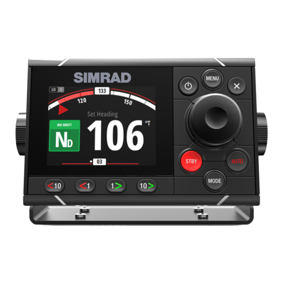
Page 10: Ap48 Front Panel And Keys
AP48 Front panel and keys 10 11 Power key • Press to show the Display setup dialog. Repeat short presses to toggle preset light levels • Press and hold to put the autopilot system to Sleep mode. Repress the key to activate the system... -
Page 11: The Autopilot Page
Rotary knob Menu and dialog operation: • Turn to move up and down in menus and dialogs • Turn to adjust a value • Press to select a menu option and to enter the next menu level In Standby mode or Non Follow Up (NFU) mode: Press to activate the Follow up (FU) mode In FU mode: Turn to set the rudder angle In automatic modes: Turn to change the set heading/set... - Page 12 For more information, refer to "Autopilot modes" on page 16. Introduction | AP™ 48 Operator Manual...
-
Page 13: Basic Operation
Basic operation Safe operation with the autopilot Warning: An autopilot is a useful navigational aid, but DOES NOT replace a human navigator. Warning: Ensure the autopilot has been installed correctly, commissioned and calibrated before use. Do not use automatic steering when: •... -
Page 14: Sleep Mode
Sleep mode In Sleep mode, the backlight for screen and keys are turned off to save power. The system continues to run in the background. To enter Sleep mode press and hold the power key or select Sleep from the Display Setup dialog activated by pressing the power key. Switch from Sleep mode to normal operation by a short press on the power key. -
Page 15: Display Setup
Display setup The display setup can be adjusted at any time from the Display setup dialog, activated by pressing the power key. The following options are available: • Backlight level: Adjusts the backlight level from Min (10%) to Max (100%) in 10% increments - When the Backlight level field is active, subsequent presses on the power key adjusts backlight level in decrements of 30% •... -
Page 16: Autopilot Modes
Autopilot modes The autopilot has several steering modes. The number of modes and features within the mode depend on the autopilot computer, the boat type and available inputs, as explained in the description of the following steering modes. Selecting an autopilot mode You select Standby mode and AUTO mode by pressing the dedicated STBY and AUTO keys. -
Page 17: Auto Mode (Heading Hold)
AUTO mode (Heading hold) In AUTO mode the autopilot issues rudder commands required to steer the vessel automatically on a set heading. In this mode the autopilot does not compensate for any drifting caused by current and/or wind (A). Switch to AUTO mode by pressing the AUTO key •... -
Page 18: Nodrift Mode
Initiate the Tack or Gybe function by selecting the Tack/Gybe • option in the Mode list. - The turn is started when the direction is selected in the dialog. NoDrift mode Ú Note: It is not possible to select NoDrift mode if GPS position and heading information is missing. -
Page 19: Heading Capture
Heading capture When the vessel is turning in AUTO mode, an instant re-press on the AUTO key or the rotary knob activates the heading capture function. This will automatically cancel the turn, and the vessel will continue on the heading read from the compass the very moment you pressed the AUTO key or the rotary knob. - Page 20 Prior to entering NAV mode the navigator must be navigating a route or towards a waypoint. • Initiate NAV mode by selecting the NAV option in the Mode list • Confirm to switch to NAV mode in the dialog. Turning in NAV mode When your vessel reaches a waypoint, the autopilot will give an audible warning and display a dialog with the new course information.
-
Page 21: Turn Pattern Steering
The limit for automatic course change is set during commisioning of the autopilot computer. For more information refer to "Autopilot settings" on page 36. Turn pattern steering The system includes a number of automatic turn steering features when the autopilot is in AUTO mode. Ú... - Page 22 • Turn variable: - Rate of turn. Increasing the value makes the vessel turn a smaller circle. U-turn Changes the current set heading to be 180° in the opposite direction. The turn rate is set during commisioning of the autopilot computer. For more information refer to "Autopilot settings"...
- Page 23 • Turn variables: - Course change (C) - Turn radius (D) Depth contour tracking (DCT) Makes the autopilot follow a depth contour. Ú Note: DCT turn pattern is only available if the system has a valid depth input. Warning: Do not use the DCT turn pattern unless the seabed is suitable.
-
Page 24: Using The Autopilot In An Evc System
Port option Starboard option (depth decreases to port) (depth decreases to starboard) • Turn variables: - Depth gain. This parameter determines the ratio between commanded rudder and the deviation from the selected depth contour. The higher depth gain value the more rudder is applied. -
Page 25: Steadysteer
When the autopilot is connected to an EVC system, you can take manual control of the steering regardless of the autopilot mode. The mode indicator is replaced by a dash to indicate EVC override. The autopilot goes into standby mode if no rudder command is given from the EVC system within a predefined period. -
Page 26: Trip Log
Trip log The Trip log is available from the Settings menu. There are three log options available: • Trip 1: records distance traveled through the water (Log input) • Trip 2: records distance traveled via GPS input • Log: shows total distance run from system installation or from a system restore Ú... -
Page 27: Alarms
Alarms The system continuously checks for dangerous situations and system faults while the system is running. The alarm system can be activated if any alarm settings are exceeded. Ú Note: If sensor data vital for autopilot operation (e.g. rudder response) is lost when the autopilot is running in an automatic mode, the system will automatically switch to Standby mode. -
Page 28: Enabling The Alarm System And The Alarm Siren
This removes the alarm notification, and silences the alarm from all units that belong to the same alarm group. Ú Note: An alarm received from non Navico units on the network must be acknowledged on the unit generating the alarm. Enabling the alarm system and the alarm siren You enable the alarm system and the alarm siren from the Alarms... -
Page 29: Alarm History
Alarm history The Alarm history dialog stores alarm messages. You show alarm details for a selected alarm and clear all alarms in the alarm history by pressing the rotary knob when the Alarm history dialog is active. Menu options Alarm details List of alarms For a list of possible alarms and corrective actions refer to "Appendixes"... -
Page 30: Software Setup
Software setup Prior to use, the AP48 requires a number of settings be configured in order for the system to perform as expected. Access to the required options are found in the Settings menu, accessed by pressing the MENU key. - Page 31 Bring the boat up to cruising speed (above 5 knots) Select the SOG reference option When the calibration is completed the Boat speed calibration scale will show the adjusted percentage value of the boat speed. Distance reference Allows you to calibrate the log via a distance reference. You will need to complete consecutive runs, under power at a constant speed made along a given course and distance.
- Page 32 Wind MHU (Masthead unit) alignment This provides an off set calibration in degrees to compensate for any mechanical misalignment between the masthead unit and the center line of the vessel. To check the masthead unit alignment error we recommend you use the following method which involves a sailing trial: •...
- Page 33 +0.5 -2.0 +0.0 Aft depth offset This option allows the system to display two depth readings. The Aft depth is calibrated in the same manner as the Depth offset. Ú Note: Aft Depth is only available when a valid signal is received from a second and compatible NMEA 2000 or NMEA 0183 device.
- Page 34 User triggered calibration Ú Note: Before the calibration is started, make sure that there is enough open water around the vessel to make a full turn. The Calibrate option is used for manually starting the heading calibration procedure. During this calibration, the compass measures the magnitude and direction of the local magnetic field.
-
Page 35: Damping
Advanced This option is used for manually applying an offset to the displayed data for third party sensors which cannot be calibrated through the AP48. Damping If data appears erratic or too sensitive, damping may be applied to make the information appear more stable. With damping set to off, the data is presented in raw form with no damping applied. -
Page 36: Autopilot Settings
Autopilot settings The autopilot settings can be split between settings done by the user, and settings done during installation and commissioning of the autopilot system. • User settings can be changed for various operational conditions or user preferences • Installation settings are defined during commissioning of the autopilot system. - Page 37 The Device list shows the devices that provide data. This may include a module inside the unit, or any external NMEA 2000 device. Selecting a device in this list will bring up additional details and actions: All devices allow allocation of an instance number in the Configure option.
- Page 38 Rx Overflows The unit received too many messages for its buffer before the application could read them. Rx Overruns The unit contained too many messages for its buffer before the driver could read them. Rx/Tx Errors These two numbers increase when there are error messages, and decrease when messages are received successfully.
- Page 39 one unit will have the same effect on the rest of the group members. Units Provides setup of units of measure used on various data types. Decimal places Defines number of decimals used for speed and sea temperature. Key beeps Controls the loudness of the beep sound when a key is pressed.
- Page 40 One gauge Two gauges Files File management system. Used to browse the contents of the unit's internal memory and the content of a device plugged into the unit's USB port. Simulate Runs the display with simulated data. Use the simulator to become familiar with your unit before using it on the water.
-
Page 41: Maintenance
Maintenance Preventive maintenance The unit does not contain any field serviceable components. Therefore, the operator is required to perform only a very limited amount of preventative maintenance. It is recommended that you always fit the supplied protective sun cover when the unit is not in use. Cleaning the display unit To clean the screen: •... -
Page 42: Software Update
Software update The AP48 includes a USB port of the back of the units. You use this port for software updates. You can update the software for the unit itself and for NMEA 2000 sensors connected to the network from the AP48. -
Page 43: Menu Tree
Menu tree The system includes a Settings menu, accessed by pressing the MENU key. The Settings menu gives access to settings for the sensors, the vessel, the autopilot computer and for the system. Level 1 Level 2 Calibration Boat speed... Wind... - Page 44 Level 1 Level 2 Autopilot Steering Available options depend on Sailing connected autopilot computer. Turn patterns Installation System Network Units Decimal places Key beeps Language Time Display Setup... Digital gauges Files Simulate Restore defaults... Global reset... About Menu tree| AP™ 48 Operator Manual...
-
Page 45: Technical Specifications
Technical specifications Dimensions Refer to "Dimensional drawings" on page 47 Weight (without accessories) 0.51 kg (1.13 lbs) Power Supply voltage 12 V (10.8V < supply voltage < 15.6V) Supply connection Micro-C (CAN) Backlight OFF 1.62 W (0.12 A @13.5 V) Backlight MAX 2.97 W (0.22 A @13.5 V) Network load 5 LEN (244 mA max) Color... - Page 46 Storage -40°C to +85ºC (-104°F to +185ºF) Technical specifications| AP™ 48 Operator Manual...
-
Page 47: Dimensional Drawings
Dimensional drawings AP48 without bracket 55.4 mm 177.0 mm 56.1 mm (2.18") (6.97") (2.21") 23.1 mm 33.0 mm (0.91") (1.30") AP48 with bracket 56.1 mm 55.4 mm 204.8 mm (2.21") (2.18") (8.06”) 84.6 mm (3.33") Dimensional drawings| AP™ 48 Operator Manual... -
Page 48: Supported Data
Supported data Ú Note: NMEA 0183 and NMEA 2000 data output requires the connection of relevant sensors. NMEA 2000 PGN (transmit) 59904 ISO Request 60928 ISO Address Claim 126208 ISO Command Group Function 126996 Product Info 127258 Magnetic Variation NMEA 2000 PGN (receive) 59392 ISO Acknowledgement 59904... - Page 49 129026 COG & SOG, Rapid Update 129029 GNSS Position Data 129033 Time & Date 129283 Cross Track Error 129284 Navigation Data 129539 GNSS DOPs 129283 Cross Track Error 129284 Navigation Data 130074 Route and WP Service - WP List - WP Name & Position 130306 Wind Data 130576 Small Craft Status 130577 Direction Data...
-
Page 50: Appendixes
Appendixes List of possible alarms and corrective actions Appendixes| AP™ 48 Operator Manual...