Simrad AP70 Operator's Manual
Hide thumbs
Also See for AP70:
- Installation manual (84 pages) ,
- Operation manual (66 pages) ,
- Quick start manual (6 pages)
Table of Contents
Advertisement
Advertisement
Table of Contents

Related Manuals for Simrad AP70


Summary of Contents for Simrad AP70
- Page 1 AP70/AP80 Operator Manual ENGLISH navico.com/commercial...
- Page 3 The AP70 and AP80 systems complies with the following regulations: • Wheelmark directive 2002/84 EC (HCS and HSC) • CE (2004-108 EC EMC Directive) - AP70 systems when used with an AC70 computer • C - Tick ¼ Note: AP70 systems are not wheelmark approved when used with an AC70 computer.
- Page 4 About this manual This manual is a reference guide for operating the Simrad AP70 and AP80 Autopilot Systems. The manual will be continuously updated to match new software releases. The latest available manual version can be downloaded from our web sites.
-
Page 5: Table Of Contents
Turn pattern steering U-turns S-turns Track steering Controlling steering performance in automatic and navigational modes Simulator mode Work profile setup The Normal profile Creating new profiles Edit a profile Importing and exporting work profiles (AP80 only) Contents | AP70/AP80 Operator Manual... - Page 6 The settings dialog and submenus System configuration General The settings dialog and submenus Turning on for the first time Network settings Installation settings Seatrials Tuning the autopilot for optimum steering performance List of display abbreviations Contents | AP70/AP80 Operator Manual...
-
Page 7: Introduction
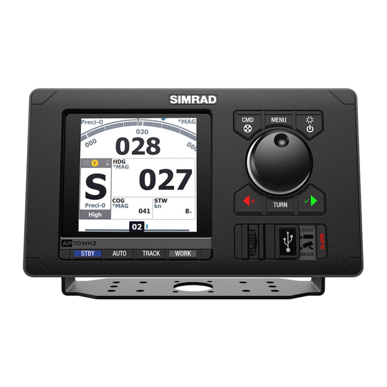
STBY. Turns the autopilot to Standby mode AUTO. Activates Auto NoDrift mode NAV (AP70) / TRACK (AP80). Activates Track steering mode WORK. Used for selecting work profile USB port door ALARM. Displays the Alarm listing dialog AP80 control units only... -
Page 8: The Screen
If a thruster is available and active, the mode info panel will be split to show thruster information. If sensor input is missing, the numbers will be replaced with hyphens. No active trusters Active thrusters No sensor input Introduction | AP70/AP80 Operator Manual... - Page 9 Icon available if one or more thrusters are installed. The icon will be shaded when the trusters are unavailable for steering Active alarm message. Red icon for alarms, yellow for warnings Control unit locked Screen alive indication - white and black “balls” fade-swap color Introduction | AP70/AP80 Operator Manual...
-
Page 10: Operational Mode Overview
Track steering. Approved for AP80 only and requires an unlock key/ code. TRACK The routes are planned on and commanded by an ECDIS (Electronic Chart Display Information System) 10 | Introduction | AP70/AP80 Operator Manual... -
Page 11: Basic Operation
When the rudder is controlled by an external FU, this will be indicated in the mode display. If you press a mode key, external control is indicated in the display. | 11 Basic operation | AP70/AP80 Operator Manual... -
Page 12: External Evc Override (Sg05 Pro
The pendulum feature is intended for pendulum ferries where it is required to turn the heading 180° when the vessel is going «backwards». The feature can be included in AP70/80 systems equipped with SD80 or AD80 boards. It can only be used for NMEA 0183 heading sensors, RC42 and CDI80. -
Page 13: Dialog Boxes
All other units will be passive. systems” on page 16 for further information A passive unit is indicated in the mode status field with passive icon, and the mode indication letter size is reduced. | 13 Basic operation | AP70/AP80 Operator Manual... -
Page 14: Selecting Autopilot Modes
Mutes the siren locally for all units in the same SimNet display group. The alarm dialog remains on the display Working with thrusters If the vessel is equipped with thrusters, they can be connected to the autopilot system. The 14 | Basic operation | AP70/AP80 Operator Manual... - Page 15 Thrusters installed and in use • Thruster(s) installed, but not configured for present work profile • Thruster(s) installed, but unavailable (vessel speed is above inhibit limit) • Thruster(s) available, but turned OFF | 15 Basic operation | AP70/AP80 Operator Manual...
-
Page 16: Delegation Of Control In Multiple Station Systems
You can temporarily lock units in an open system if you want to avoid accidental control from another control unit An active AP70/AP80 control unit can lock and unlock all passive control units. Activate the lock function from any active control unit by a single press on the CMD key De-activate the function with a second press on the CMD key Active locking function is indicated with a lock symbol on both active and passive units. -
Page 17: Master Systems
In the illustration below the main bridge is defined as master station. One QS80, one AP80 control unit and one AP70 control unit are included in the master station. The AP80 control unit is defined as the Master unit. - Page 18 Take command on selected remote by pressing the CMD key Command will be transferred to this remote, accompanied by a 2 second sound All other remote units will return to locked status 18 | Delegation of control in multiple station systems | AP70/AP80 Operator Manual...
- Page 19 The requesting remote will now be opened for command transfer. All other units will remain locked Take command on requesting remote by pressing the CMD key Command will be transferred to this remote, accompanied by a 2 second sound | 19 Delegation of control in multiple station systems | AP70/AP80 Operator Manual...
-
Page 20: The Operational Modes
The mode descriptions in the following pages assumes that an external system selector has 11 for further information opened for autopilot operation, or that no external selector is installed. 20 | The operational modes | AP70/AP80 Operator Manual... -
Page 21: Hand Steering
The Quick menu includes access to the Settings dialogs. • Activate the Quick menu by a short press on the MENU key | 21 The operational modes | AP70/AP80 Operator Manual... -
Page 22: Auto Modes
Source setup is done on initial start up of the system. It is also required to run the source selection if any part of the network has been changed or replaced. See the separate AP70/AP80 Installation manual for more details. Automatic source selection The Auto Select option will look for all sources connected to the network. - Page 23 ¼ Note: The PORT and STBY keys will always give immediate action, also when turn preset function is active. | 23 The operational modes | AP70/AP80 Operator Manual...
- Page 24 Select one of the preset course increment values in the Turn Settings dialog ¼ Note: If 0.1 is selected, the set heading/course will be displayed with one decimal in the mode info panel. 24 | The operational modes | AP70/AP80 Operator Manual...
-
Page 25: Turn Pattern Steering
The S-turns are only available in mode. Activating the S-turn option Before the S-turns mode can be applied it must be enabled in the turn settings thus making it available in the turn settings dialog. | 25 The operational modes | AP70/AP80 Operator Manual... - Page 26 Warning: Navigational steering should only be used in open waters. The AP70 and AP80 can use steering information from an external navigator to direct the vessel to one specific waypoint location, or through a series of waypoints. mode the autopilot will steer straight legs along a route set on chart plotter ¼...
- Page 27 Start navigating Start navigating a route on your chart system Press the NAV (AP70) or TRACK key (AP80) on the autopilot Accept the waypoint as the location to steer towards to activate the navigational mode If the waypoint is not accepted within 8 seconds, the dialog will be removed and the autopilot will remain in active mode Red or green arrow symbol in the dialog indicates required course change direction.
-
Page 28: Track Steering
Track steering With AP70/80 software release 1.2 the AP80 system and a Simrad CS68 ECDIS forms a fully type approved Track steering system according to IEC62065 ed.1. The routes are planned on and commanded by an ECDIS (Electronic Chart Display Information System). - Page 29 Unlocking the Track steering feature A unlock key must be obtained from Navico to unlock the Track steering feature. Contact a Simrad Sales office for further information. Device list Navigate to the dialog, and select the autopilot computer where you want to install the feature Press the Rotary knob or the Right arrow key to bring up the computer’s information dialog...
- Page 30 Before the AP80 can be used for track steering, the system must be setup and configured according to the separate AP70/80 Installation manual. The wiring to the ECDIS system must be according to previous section, and both the ECDIS system and the AP80 system must be configured as previously described.
-
Page 31: Controlling Steering Performance In Automatic And Navigational Modes
An unstable vessel will require high settings • The greater the vessel’s inertia, the greater value will be required Increasing counter rudder settings may result in some higher rudder activity also when steering a straight course. | 31 The operational modes | AP70/AP80 Operator Manual... -
Page 32: Simulator Mode
When the simulator is toggled on this is indicated with a flashing message in the lower part of the display. ¼ Note: Simulator mode is not available if the unit is connected to the CAN bus. 32 | The operational modes | AP70/AP80 Operator Manual... -
Page 33: Work Profile Setup
Work profile setup A work profile is a set of steering parameters used by the AP70/AP80 system to improve the autopilot steering under different operational conditions. This gives high steering performance very quickly when the operational conditions change, compared to waiting for the autopilot adaption process. - Page 34 This parameter counteracts the effect of the vessel turn rate and inertia. • Range: 0.05 - 8.00 • Default: Depends on the vessel length • Initial value: Determined during sea trial Auto trim 34 | Work profile setup | AP70/AP80 Operator Manual...
- Page 35 Defines how the system moves the rudder when switching from power steering to an automatic mode: Midships moves the rudder to zero position. Actual maintains the rudder offset, and use this as trim value (bumpless transfer) | 35 Work profile setup | AP70/AP80 Operator Manual...
- Page 36 When the feature is enabled, one rudder will stop moving before the other one if max/ min rudder angles are demanded. When the feature is enabled, the rudder bar on AP70/80 and QS-/NF-/FU80 shows rudder command instead of measured rudder angle.
-
Page 37: Edit A Profile
Press the WORK key to display all work profiles Turn the rotary knob to select the edit icon on the work profile you want to change Make the required changes and save the new settings | 37 Work profile setup | AP70/AP80 Operator Manual... -
Page 38: Importing And Exporting Work Profiles (Ap80 Only
¼ Note: The work profile files have .wpf extension! Press the LEFT key or the rotary knob to access the file details Select Import Confirm your selection Save the new work profile 38 | Work profile setup | AP70/AP80 Operator Manual... - Page 39 Return to the work dialog and confirm that the imported work profile is available ¼ Note: The first 6 characters in the file name will be used as profile name. | 39 Work profile setup | AP70/AP80 Operator Manual...
-
Page 40: The Alarm System
The alarm system The AP70/AP80 system will continuously check for dangerous situations and system faults while the system is running. Message types There are two type of messages: • Alarms Generated when conditions are detected that critically effect the capability or performance of the system. -
Page 41: The Alarm Dialogs
List of all active messages • Alarm history Alarm events, including alarm type and time/date • Alarm settings List of all alarms that can be enabled and configured by the user | 41 The alarm system | AP70/AP80 Operator Manual... -
Page 42: Setting The Alarm And Warning Limits
Rudder is kept at fixed angle (i.e. heading is approximately maintained if failing when heading keeping, turn is approximately maintained if failing when turning), alarm is given and STBY autopilot goes to mode. 42 | The alarm system | AP70/AP80 Operator Manual... -
Page 43: Backup Navigator Alarm (Ap80 Only)
The backup navigator alarm can only be acknowledged from AP80. To enable this feature, the autopilot system provides a configurable handshake port on SD80 or AD80 that can be connected to an external alarm panel or loudspeaker. | 43 The alarm system | AP70/AP80 Operator Manual... -
Page 44: List Of Possible Alarms And Corrective Actions
List of possible alarms and corrective actions The next pages includes a list of all alarms generated by the autopilot system. The AP70/AP80 control units might also display alarms received from other units connected to the system. Refer separate documentation for the relevant equipment for further descriptions of these alarms. - Page 45 9-15 V between NET-S and NET-C of SimNet device plug. If led is ok, check cabling, T-connector backbone etc. If led is on, try to restart unit by turning power off/on | 45 The alarm system | AP70/AP80 Operator Manual...
- Page 46 Boats heading is outside set Check steering parameters (Rudder, Autotrim, Seastate- Off heading off heading limit. Automatic filter) reset when inside limit Increase Response/Rudder value Increase boat speed, if possible, or steer by hand 46 | The alarm system | AP70/AP80 Operator Manual...
- Page 47 Thruster inhibited Vessel speed > set limit ¼ Note: The Thruster inhibit limit will only apply when speed source is Log or SOG, not if the speed is set manually. | 47 The alarm system | AP70/AP80 Operator Manual...
-
Page 48: Maintenance
Maintenance Preventive maintenance The AP70/AP80 control units do not contain any field serviceable components, therefore the operator is required to perform only a very limited amount of preventative maintenance. To prevent UV damage to the plastic bezel and rubber keys, it is recommended that the sun cover (option) be fitted when the unit is not in use for an extended period. -
Page 49: Software Upgrades
Software upgrades The latest software for the AP70/AP80 will be available for download from our web sites: www.navico.com/commercial and www.simrad-yachting.com. Detailed instructions for how to install the software will follow the upgrade files. Backing up your system data It is recommended to copy the user settings files after the system has been commissioned. -
Page 50: Menu Overview
Quick menu. The different settings are described in “Controlling steering performance in automatic and navigational modes” on page 31. Auto mode LEVEL 1 Rudder (Adj.) Ctr.rudder (Adj.) Speed (Adj.) Settings (Settings dialog/menus) 50 | Menu overview | AP70/AP80 Operator Manual... -
Page 51: The Settings Dialog And Submenus
The system is configured and most system settings defined during installation and commissioning of the system. All system configuration and Installation setup is described in the separate AP70/AP80 Installation manual. The settings parameters are logically grouped, and each group is presented with an icon in the Settings dialog. - Page 52 List of devices connected to the CAN bus network. Used for setup, diagnostics and configuration. See “System configuration” on page 53. Installation Includes dockside and seatrial calibrations. See “System configuration” on page 53. 52 | Menu overview | AP70/AP80 Operator Manual...
-
Page 53: System Configuration
The first time the autopilot system is started and after a factory reset, you will be guided through a set of initial settings. If the settings are not completed, you can configure the autopilot system manually as described in the following sections. | 53 System configuration | AP70/AP80 Operator Manual... -
Page 54: Network Settings
The autopilot system can use data sources that all other products on the network use, or select individual sources for the autopilot system. If the group is set to Simrad, any changes to a source will also affect other systems on the network. -
Page 55: Device List
Press the MENU key, the STBD key or the rotary knob to see selected device details. ¼ Note: The graphics show gyro input on an SI80 board. Device details and options depends on data type. Diagnostics The diagnostic page shows details for the NMEA 2000/CAN bus network. | 55 System configuration | AP70/AP80 Operator Manual... - Page 56 It will not change the light settings on the bridge. If the damping is adjusted on the AP80 control unit, this will also affect damping on the NSE unit in the remote station. MAIN BRIDGE NF80 AP80 CONTROL HEAD MENU TURN STBY AUTO WORK REMOTE STATION QS80 56 | System configuration | AP70/AP80 Operator Manual...
- Page 57 In the illustration below the main bridge is defined as master station. One QS80, one AP80 control unit and one AP70 control unit are included in the master station. The AP80 control unit is defined as the Master unit.
-
Page 58: Installation Settings
When the drive configuration is completed this is indicated with a tick after the drive name. The dialog will not illustrate drive type and location before the drive location and type is defined. 58 | System configuration | AP70/AP80 Operator Manual... - Page 59 SimNet plug on the board ¼ Note: The label below is an example only and varies with board type. AD80 AD80 | 59 System configuration | AP70/AP80 Operator Manual...
- Page 60 The pendulum feature is intended for pendulum ferries where it is required to turn the heading 180° when the vessel is going «backwards». The feature can be included in AP70/80 systems equipped with SD80 or AD80 boards. It can only be used for NMEA 0183 heading sensors, RC42 and CDI80.
- Page 61 “External” and use the installed current or voltage input to the RUD UI plug of SD80/AD80 board for follow up rudder control. ¼ Note: Must be limited to one autopilot computer board | 61 System configuration | AP70/AP80 Operator Manual...
- Page 62 When input contact is closed, a command transfer by command transfer dialogue is started (refer Command transfer description in the AP70/AP80 Operator Manual). When accepted, the output contact will close and use the installed current or voltage input to the RUD UI plug of SD80/AD80 board for follow up rudder control.
- Page 63 On power boats it is recommended that you set a value that represents the speed where the hull begins to plane or the speed where you change from slow to cruising speed. | 63 System configuration | AP70/AP80 Operator Manual...
- Page 64 Midships moves the rudder to zero position. Actual maintains the rudder offset, and use this as trim value (bumpless transfer) ¼ Note: Actual is only available with rudder feedback signal available. • Default: Midships 64 | System configuration | AP70/AP80 Operator Manual...
-
Page 65: Seatrials
¼ Note: Calibration must be made on the compass that is active for the autopilot. If another model compass from Simrad or another manufacturer is installed, refer to the calibration instruction for that compass. ¼ Note: In certain areas and at high latitudes the local magnetic interference becomes more significant and heading errors exceeding ±3°... -
Page 66: Tuning The Autopilot For Optimum Steering Performance
Stabilize the vessel on a heading, and then select mode Observe course keeping and rudder commands The autopilot should keep the vessel on the set heading within an average of +/-1 degree, providing calm sea and wind 66 | System configuration | AP70/AP80 Operator Manual... - Page 67 The settings depends on vessel’s characteristics, loaded/ballast conditions and rate of turn. • If the vessel has good dynamic stability, relatively small settings will be sufficient | 67 System configuration | AP70/AP80 Operator Manual...
- Page 68 Counter rudder that gives a little overshoot to one side and a bit sluggish response to the other. • Range: 0.05 - 32.00 • Default: Defined by system based on boat type and length 68 | System configuration | AP70/AP80 Operator Manual...
-
Page 69: List Of Display Abbreviations
Bearing Waypoint to Waypoint Course Over Ground Course Course To Steer Distance To Waypoint Heading Manual (speed input) Speed Over Ground Speed Through Water Waypoint (followed by waypoint name) Cross Track Distance | 69 List of display abbreviations | AP70/AP80 Operator Manual... - Page 70 70 | List of display abbreviations | AP70/AP80 Operator Manual...