Table of Contents
Advertisement
Quick Links
Advertisement
Table of Contents
Troubleshooting

Related Manuals for Mitel CPDM3


Summary of Contents for Mitel CPDM3
- Page 1 CPDM3 INSTALLATION GUIDE...
- Page 2 The information is subject to change without notice and should not be construed in any way as a commitment by Mitel or any of its affiliates or subsidiaries. Mitel and its affiliates and subsidiaries assume no responsibility for any errors or omissions in this document. Revi- sions of this document or new editions of it may be issued to incorporate such changes.
- Page 3 Installation Guide About this document This document is used for installation and configuration of the CPDM3, as well as for administration and troubleshooting. Target groups • The field engineer that installs, maintains and troubleshoots the system • The system administrator responsible for the IT management at the customer site, that needs to get error messages, to survey and have control of the system.
-
Page 4: Table Of Contents
Installation Guide Contents Introduction......................2 1.1 Abbreviations and Glossary..................3 2. General Information.................... 4 2.1 Licenses ......................4 2.2 MAC Address ....................4 2.3 Authentication and Administration ..............4 3. Description ......................6 3.1 Overview of Connectors, Buttons and LEDs ..........6 3.2 Label for IP Address/Host Name .............. -
Page 5: Introduction
Installation Guide 1. INTRODUCTION The CPDM3 is used for messaging, alarm handling, administration and device management. It can be used independently but also works in combination with other CPDM3s or systems. The software of CPDM3 is pre-installed on a hardware equipped with: •... -
Page 6: Abbreviations And Glossary
9, or Mozilla Firefox™ 3.6 through 12. 1.1 ABBREVIATIONS AND GLOSSARY Graphical User Interface SD card a non-volatile Secure Digital memory card CPDM3 Centralized Portable Device Manager. The CPDM3 is called “product” in this document. 34/1531-ANF901 43 B1 2016-03-31... -
Page 7: General Information
Installation Guide 2. GENERAL INFORMATION 2.1 LICENSES The product’s software installed on the hardware must have a valid software license. The license number can be found: • on the license certificate provided with the product • in the product’s Setup Wizard •... - Page 8 Installation Guide 2.3.2 ADMINISTRATION The Advanced Configuration page requires the sysadmin/admin account. The page can be reached directly by entering “xxx.xxx.xxx.xxx/admin” in a web browser, where xxx.xxx.xxx.xxx is the product’s IP address. The Advanced Configuration page can also be accessed by clicking the “Configuration” button on the Start page and then selecting Other Settings >...
-
Page 9: Description
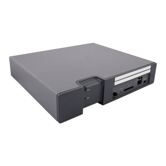
Installation Guide 3. DESCRIPTION The front side of the product’s hardware has different status indications and is used for maintenance. The LEDs indicate the status of the product and the management port makes it possible to have direct connection to the product. It also has an SD card slot and two USB ports for use with external temporary devices. -
Page 10: Label For Ip Address/Host Name
Installation Guide LAN 1 S900 100-240V 275mA 50-60 Hz COM 1 A-bus Error 12-24 V DC 1A COM 2 LAN 2 S900 A-bus Error 12-24 V DC 1A Rear side Serial (COM) connections: 2 × RS232 (D-sub-9 male connectors), used for external interfaces (ESPA, Ascom Line protocol, and TAP) LAN: 2 (One is not used) ×... -
Page 11: Led Indications
Installation Guide The blank label is found on the back side of the Getting started document: “Elise3 – EMBEDDED LINUX SERVER INCLUDING SAFETY INFORMATION”, included in the delivery. Figure 3. Label for IP address or host name 3.3 LED INDICATIONS The LEDs show different colors to determine type of information and have different flashing frequency for showing the priority. -
Page 12: Operating Mode
Installation Guide Status LED Status OK Blue Starting up/shutting down Blue Feedback (1 sec.) Blue Error/fault Mode LED Warning Boot mode Yellow Blue Power LED Demonstation mode Yellow Blue Active module during Blue synchronization Blue Blue Active module synchronized Standby module during Blue Yellow synchronization... - Page 13 Installation Guide 5. Working in Boot Mode on page 25. 3.4.3 DEMONSTRATION MODE Demonstration Mode makes it possible to run the product’s software for two hours with full or almost full functionality, with or without a valid license. Exact functionality is software dependent.
-
Page 14: Installation And Configuration
Installation Guide 4. INSTALLATION AND CONFIGURATION The hardware can be mounted vertically on a wall or be placed horizontally in a 19” rack. It must be fixed by screws or other fixtures to the wall or rack, and must not be easily movable. - Page 15 Installation Guide Connectors Connectors 4.1.3 RACK MOUNTING The hardware can be either front mounted or reverse mounted in a 19” rack. Accessories for mounting in a rack (ordered separately). Item No. Rack 660324 Standard 19” rack kit: Small left/right brackets for two front mounted hardware and one big bracket for one front mounted hardware.
- Page 16 Installation Guide Fasten the assembly brackets in the rack as shown in the figure below (screws not included). Front mounted double Front mounting of double hardware requires the standard 19” rack kit. Use the supplied assembly brackets and fasten the two hardware together, both on the rear side and on the bottom side, as shown in the figures below.
- Page 17 Installation Guide Use the two small standard assembly brackets and fasten one on the right front side and the other on the left front side. Fasten the assembly brackets in the rack as shown in figure below (screws not included). Rear mounted single Rear mounting of single a hardware requires the reverse 19”...
- Page 18 Installation Guide Rear mounted double Rear mounting of double hardware require the reverse 19” rack kit. Use the supplied assembly brackets and mount the two hardware together, both on the rear side and on the bottom side as shown in figure below. Use the two small reverse assembly brackets and fasten one on the right rear side and the other on the left rear side.
-
Page 19: Supply Voltage
Installation Guide 4.2 SUPPLY VOLTAGE The hardware can be connected to an external power supply (12-24 Vdc battery or power source) as a complement to the primary power supply (100-240 Vac). If the primary power supply fails it switches over to the external power supply automatically, without any negative influence on the running application. -
Page 20: Connections
Installation Guide Select Other Settings > Advanced Configuration in the menu on the Configuration page. Select Power supply in the menu on the Advanced Configuration page. Select setting in the drop-down list (Internal PSU only, External PSU only, Internal and external PSU or Internal PSU and external battery). Click “Activate”. - Page 21 Installation Guide S900 A-bus 4.3.4 ERROR RELAY OUTPUT A relay output is used to indicate product malfunction and to indicate errors. Connections are made with twisted pairs to 1 and 2 on screw connector. Figure 8. Error relay +V In In Out Out GND Error Ext 1 2 Ext...
-
Page 22: Accessing Product
Installation Guide +V In In Out Out GND Error Ext 1 2 Ext External equipment Power supply 12/24 V DC If galvanic isolation is not needed and the hardware is supplied by an external 12 Vdc/24 Vdc power source, the supply voltage can be taken from the 12-24 Vdc screw connector by connecting +V Ext to “+”... - Page 23 Installation Guide NOTE: If NetBIOS is enabled in the network, the address elise-XXXXXXXX can be used when accessing the product via the network, where XXXXXXXX is the module key number. The module key number can be found on the license certificate or on the label on the back of the hardware.
- Page 24 Installation Guide Install the Port Driver on Windows Vista NOTE: When switching between mass storage mode and network mode, it takes about 30 seconds before the product can be accessed with the 192.5.36.229 address. Connect a mini-USB type B cable between the USB port on your computer and the management port on the product.
- Page 25 Installation Guide Install the Port Driver on Windows 7 NOTE: When switching between mass storage mode and network mode, it takes about 30 seconds before the product can be accessed with the 192.5.36.229 address. Connect a mini-USB type B cable between the USB port on your computer and the management port on the product.
-
Page 26: Basic Configuration
Installation Guide Click “Install this driver software anyway”. The installation of the port driver begins. Click “Close” when the installation has finished. The port driver “Linux USB Ethernet/RNDIS Gadget” is now installed in Control Panel > Hardware and Sound > Devices and Printers > Device manager > Network adapters 4.5 BASIC CONFIGURATION The product needs to be configured with basic settings. - Page 27 Installation Guide Select “Restart immediately” when the setup wizard has finished. The product will restart with the new configuration. 4.5.2 CHANGE SECURED SETTINGS To be able to activate some security settings it is required that someone physically confirms the changes on the product. This is a security feature due to the remote access (LAN or VPN) ability on the product.
-
Page 28: Working In Boot Mode
Installation Guide 5. WORKING IN BOOT MODE If the software installed on the product cannot be started, the Boot Mode can be used for installing new software, see settings, performing factory reset, troubleshooting and also starting up in normal operation again. If the product detects several major errors (for example restart loop), the product can set itself in Boot Mode. - Page 29 Installation Guide 5.1.2 NETWORK SETTINGS Under System > Network the network settings are shown. All network settings can be edited in this view if DHCP is disabled, but only the Host name if DHCP is enabled. NOTE: The IP address 192.5.36.229 cannot be assigned to the product when it is connected to the LAN.
- Page 30 Installation Guide Set the product in Boot Mode, see 5.1 Set Product in Boot Mode on page 25. Select Software > Install software. Click the “Browse...” and locate the software (.pkg) file to install. Select where to save the software. If two versions of the software already have been installed on the module choose which software to replace.
-
Page 31: Demonstration Mode
Installation Guide 6. DEMONSTRATION MODE The Demonstration Mode can be set when the module is running in normal operation, either via the product’s web interface or manually by using the Mode button. Press and hold the Mode button for 10 seconds. Demonstration Mode is indicated by the Status LED with slow flashing yellow light and by the Mode button LED with fixed blue light The module will automatically return to the previous license and parameters (without... -
Page 32: Maintenance
Installation Guide 7. MAINTENANCE 7.1 SOFTWARE MANAGEMENT 7.1.1 INSTALLATION OF SOFTWARE Normally the installation of software is done from the product’s web interface but it can also be done in Boot Mode, see 5.1.3 Install Software in Boot Mode on page 26. 7.1.2 CREATE BACKUP OF SOFTWARE SETTINGS Normally the backup is done from the product’s web interface but it can also be done in Boot Mode. -
Page 33: Restarting The Product
Installation Guide 7.2 RESTARTING THE PRODUCT 7.2.1 CONTROLLED RESTART USING RESTART BUTTON When a controlled restart is performed via the Restart button, all ongoing jobs on the product ends in a controlled way and everything is logged. When the product has shut down, the user can unplug the power cable or wait one minute for the product to automatically start up again. -
Page 34: Troubleshooting
Installation Guide 8. TROUBLESHOOTING Troubleshooting is normally done by accessing the product’s web interface to see logs, statistics etc. But if for some reason the application's web interface cannot be reached, it is possible to get access to the information by placing the product in Troubleshoot mode. -
Page 35: Troubleshooting From Boot Mode
Installation Guide 8.1 TROUBLESHOOTING FROM BOOT MODE Via the Troubleshoot button in the Boot Mode GUI, you get access to the product’s web interface (no applications are running) and will be able to see logs and other information. When troubleshooting, it is always a good idea to examine the log files, since they provide additional information that may prove useful. -
Page 36: Related Documents
Installation Guide 9. RELATED DOCUMENTS Installation and Operation Manual, CPDM3 34/1531-ANF901 43 B1 2016-03-31...