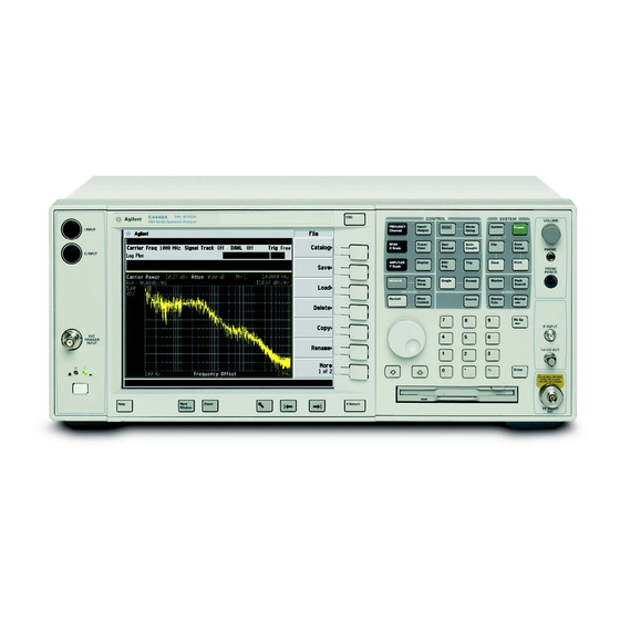
Agilent Technologies E4440A Installation Notes
Spectrum analyzer option bab, apc 3.5 input connector retrofit kit
Hide thumbs
Also See for E4440A:
- Getting started manual (80 pages) ,
- Custom installation notes (12 pages) ,
- Service manual (436 pages)
Summary of Contents for Agilent Technologies E4440A
- Page 1 Installation Note Agilent Technologies E4440A Spectrum Analyzer Option BAB, APC 3.5 Input Connector Retrofit Kit Part Number E4440-90092 Printed in USA March 2002...
- Page 2 The information contained in this document is subject to change without notice. Agilent Technologies makes no warranty of any kind with regard to this material, including but not limited to, the implied warranties of merchantability and fitness for a particular purpose.
- Page 3 Introduction The Option BAB retrofit kit provides all the parts and instructions necessary to install the APC 3.5 input connector into the Agilent E4440A spectrum analyzer. The Option BAB is licensed for one instrument model number/serial number combination. The kit will only function on the instrument it was ordered for.
- Page 4 Option BAB Hardware Retrofit Kit Contents Description Agilent Part Quantity Number License keyword certificate for Option BAB N.A. Installation Note 0515-0372 Screws, M3x0.5 8mm-LG (Crest Washer-Pan Head-TORX) APC 3.5 Input Connector Assembly E4440-60335 The input connector assembly is made up of: W7, Input Cable semi-rigid Input connector, APC 3.5 Bracket, APC 3.5...
-
Page 5: Installation Procedure
Installation Procedure Installation Procedure 1. Perform the following procedures in order: a. Remove the instrument outer case. b. Remove the instrument top brace. c. Drop the front frame. d. Install the Option BAB retrofit kit. e. Install the front frame, instrument top brace, and outer case. f. - Page 6 Installation Procedure Figure 1 Instrument Outer Case Removal E4440-90092...
- Page 7 Installation Procedure Remove the Top Brace 1. Refer to Figure 2. Use the T-10 driver to remove the top screws (3) (one screw is under the security label), and the side screws (2) attaching the top brace (1) to the deck.
- Page 8 Installation Procedure Drop the Front Frame 1. Refer to Figure 3. Using the T-10 driver, remove the 7 screws (1) that attach the front frame assembly (2) to the deck. 2. Pull the front frame off of the deck until it is disengaged from the disc drive. 3.
- Page 9 Installation Procedure Remove the RF Input Connector 1. Refer to Figure 4. Using a 5/16 inch wrench, disconnect the semi-rigid cable (1) from the A14 attenuator. 2. Using the T-10 driver, remove the 2 screws (2) that secure the input connector bracket to the deck.
- Page 10 Installation Procedure Install the Option BAB RF Input Connector 1. Remove the APC 3.5 input connector assembly from the kit. 2. Loosen, but don’t remove the semi-rigid cable that is attached to the input connector assembly. 3. Install the connector assembly into the instrument. Attach the semi-rigid cable to the A14 attenuator, but don’t tighten 4.
- Page 11 At minimum, perform the Frequency Response performance test. For assistance, contact your nearest Agilent Technologies Sales and Service Office. To find your local Agilent office access the following URL or call the following telephone number: http://www.agilent.com/find/assist...
- Page 12 ** For Agilent Internal Reference Only ** Manufacturing Part Number Customer Order Number E4440-90092 Printed in USA March 2002...


