Agilent Technologies E4443A Installation Notes
Spectrum analyzer
Hide thumbs
Also See for E4443A:
- Service manual (436 pages) ,
- User and programming manual (434 pages) ,
- Manual (382 pages)
Advertisement
Quick Links
Installation Note
Agilent PSA Series Spectrum Analyzer
E4440A, E4443A, E4445A
Option 322 Retrofit Kit
(required to retrofit Option 122, 80 MHz
Bandwidth Digitizer
Option 340 Retrofit Kit
(required to retrofit Option 140, 40 MHz
Bandwidth Digitizer
Part Number E4440-90611
Printed in USA April 2008
Advertisement

Related Manuals for Agilent Technologies E4443A


Summary of Contents for Agilent Technologies E4443A
- Page 1 Installation Note Agilent PSA Series Spectrum Analyzer E4440A, E4443A, E4445A Option 322 Retrofit Kit (required to retrofit Option 122, 80 MHz Bandwidth Digitizer Option 340 Retrofit Kit (required to retrofit Option 140, 40 MHz Bandwidth Digitizer Part Number E4440-90611 Printed in USA April 2008...
- Page 2 The information contained in this document is subject to change without notice. Agilent Technologies makes no warranty of any kind with regard to this material, including but not limited to, the implied warranties of merchantability and fitness for a particular purpose.
- Page 3 Wide Bandwidth Retrofit Kit Wide Bandwidth Retrofit Kit 80 MHz Bandwidth Digitizer Retrofit Kit 40 MHz Bandwidth Digitizer Retrofit Kit Products Affected: PSA E4440A PSA E4443A PSA E4445A Serial Numbers: US4611 /US99999999 MY4611 /MY99999999 SG4611 /SG99999999 To Be Performed By:...
- Page 4 Wide Bandwidth Retrofit Kit Contents Reference Description Agilent Part Designator Number Wide Band Analog IF Assembly E4440-60215 Wide Band Digital IF Assembly E4440-60262 Bandpass Filter, 3.900 GHz 0955-1391 Lowpass Filter, 4.4 GHz 0955-0519 Cable, ribbon, A31 Wide Band Analog IF to E4440-60341 A32 Wide Band Digital IF Cable (65), coax, 100 MHz Ref from A11 Reference Assy J2...
- Page 5 Wide Bandwidth Retrofit Kit Tools Required ❏ T-20 Torx driver ❏ T-10 Torx driver ❏ 5/16-inch torque wrench ❏ 8 mm deep socket or open end wrench ❏ 7/32 inch or 6 mm open end wrench ❏ Calibration software. Latest software information and downloads available at http://www.agilent.com/find/calibrationsoftware ❏...
-
Page 6: Installation Procedure
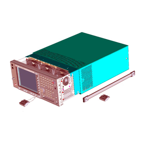
Installation Procedure Installation Procedure Remove the Outer Case CAUTION If the instrument is placed on its face during any of the following procedures, be sure to use a soft surface or soft cloth to avoid damage to the front panel, keys, or input connector. 1. - Page 7 Installation Procedure Remove the Top Brace 1. Refer to Figure 2. Use the T-10 driver to remove the top screws (3) (one screw is under the security label), and the side screws (2) attaching the top brace (1) to the deck.
- Page 8 Installation Procedure Install the Retrofit Kit Changes to the Card Cage Area 1. Locate the A7 Digital IF assembly. It is in the forth card slot from the power supply. Refer to Figure Figure 3 A7 Digital IF Assembly Location 2.
- Page 9 Installation Procedure 5. Refer to Figure 4. Install the A31 Wideband Analog IF assembly into the board slot next to the A7 Digital IF. This slot is the third slot from the power supply. 6. Locate in the kit, and install the A32 Wideband Digital IF assembly next to the A31 Wideband IF assembly just installed.
- Page 10 Installation Procedure Figure 5 Cable Routing 11.Reinstall the A10 3rd Converter assembly. Re-attach all cables being sure to follow the color code on the board. 12.Locate the cable with the “60” color code in the kit. Connect the SMB end to the A10 3rd Converter J6 (60).
- Page 11 Installation Procedure 14.Attach the W66 cable to the SMB connector on the A31 Wideband Analog IF assembly. This is the cable you left unattached in step 15.Locate the cable with the “95” color code in the kit. Connect the SMB end of the cable to the A11 Reference assembly's 300 MHZ Out connector.
- Page 12 Installation Procedure Changes to the RF Section 18.Figure 6 shows the completed installation of replacement filter FL2, the additional filter FL3 and the associated cables. Refer to this figure when completing the rest of the installation, and to determine the location of the components. Figure 6 RF Section Part Locations 19.Locate FL2 in the instrument and completely remove the cable that connects from the...
- Page 13 Installation Procedure 26.Refer to Figure 6. Install the W78 cable from the top of FL2 to FL3. Connect the W79 cable from the other end of FL3 to A20 Lowband Assembly at J4. Use a 7/32 or 6mm open end wrench to hold the center of FL3 when torquing the cable connectors to 10 inch pounds 27.Use the cable tie contained in the kit to secure FL3 to the semi rigid cable that runs parallel to FL3.
- Page 14 Installation Procedure Installing the Option Designator and License Keyword NOTE The option designator 122 or 140 and the license keyword must be entered into instrument memory in addition to the correct firmware before the hardware will function. 1. Follow the directions on the Option Upgrade Entitlement Certificate included in the kit.
- Page 15 Installation Procedure Perform Test Routines using the Agilent Calibration and Adjustment Software The latest software information and downloads are available at http://www.agilent.com/find/calibrationsoftware Calibration Constant Resets Required WB IF Cal Constant Reset Under Test Plan, select Utilities and Calibration Constant Reset. Perform the test listed above.
- Page 16 15 dB of each other, and at least 20 dB above the noise floor. End of installation. For assistance, contact the nearest Agilent Technologies Sales and Service Office. To find your local Agilent office access the following URL: http://www.agilent.com/find/assist...