Table of Contents
Advertisement
Quick Links
Advertisement
Table of Contents

Related Manuals for TiePie Handyscope HS5 Series


Summary of Contents for TiePie Handyscope HS5 Series
- Page 1 Handyscope HS5 User manual TiePie engineering...
- Page 2 Copyright c 2016 TiePie engineering. All rights reserved. Revision 2.14, January 2016 Despite the care taken for the compilation of this user manual, TiePie engineering can not be held responsible for any damage resulting from errors that may appear in this manual.
-
Page 3: Table Of Contents
Contents 1 Safety 2 Declaration of conformity 3 Introduction 3.1 Sampling ......3.2 Sample frequency ....3.2.1 Aliasing . - Page 4 8.4 AUX I/O ......32 9 Specifications 9.1 Acquisition system ....33 9.2 Acquisition system (continued) .
-
Page 5: Safety
flammable gases or fumes. Do not use the equipment if it does not operate properly. Have the equipment inspected by qualified service personal. If necessary, return the equipment to TiePie engineering for service and repair to ensure that safety features are main- tained. - Page 6 Chapter 1...
-
Page 7: Declaration Of Conformity
Declaration of conformity TiePie engineering Koperslagersstraat 37 8601 WL Sneek The Netherlands EC Declaration of conformity We declare, on our own responsibility, that the product Handyscope HS5-540(XM/S/XMS) Handyscope HS5-530(XM/S/XMS) Handyscope HS5-220(XM/S/XMS) Handyscope HS5-110(XM/S/XMS) Handyscope HS5-055(XM/S/XMS) for which this declaration is valid, is in compliance with... - Page 8 Environmental considerations This section provides information about the environmental impact of the Handyscope HS5. Handyscope HS5 end-of-life handling Production of the Handyscope HS5 required the extraction and use of natural resources. The equipment may contain substances that could be harmful to the environment or human health if improperly handled at the Handyscope HS5’s end of life.
-
Page 9: Introduction
Introduction Before using the Handyscope HS5 first read chapter about safety. Many technicians investigate electrical signals. Though the measurement may not be electrical, the physical variable is of- ten converted to an electrical signal, with a special transducer. Common transducers are accelerometers, pressure probes, current clamps and temperature probes. - Page 10 The Handyscope HS5 supports high speed continuous streaming measurements. The maximum streaming rates are: Resolution Handyscope HS5 Channels 8 bit 12/14 bit 16 bit 40 MS/s 20 MS/s Model 540 6.25 MS/s CH1+CH2 20 MS/s 10 MS/s 40 MS/s 20 MS/s Model 530 6.25 MS/s CH1+CH2...
-
Page 11: Sampling
With the accompanying software the Handyscope HS5 can be used as an oscilloscope, a spectrum analyzer, a true RMS voltmeter or a transient recorder. All instruments measure by sampling the input signals, digitizing the values, process them, save them and display them. -
Page 12: Sample Frequency
Figure 3.2: ”connecting” the samples Sample frequency The rate at which the samples are taken is called the sampling frequency, the number of samples per second. A higher sampling frequency corresponds to a shorter interval between the samples. As is visible in figure 3.3, with a higher sampling frequency, the original signal can be reconstructed much better from the measured samples. -
Page 13: Aliasing
ples per period are recommended to be able to examine the signal thoroughly. 3.2.1 Aliasing When sampling an analog signal with a certain sampling frequency, signals appear in the output with frequencies equal to the sum and difference of the signal frequency and multiples of the sampling frequency. -
Page 14: Digitizing
Figure 3.4: Aliasing In figure 3.4, the green input signal (top) is a triangular signal with a frequency of 1.25 kHz. The signal is sampled with a fre- quency of 1 kHz. The corresponding sampling interval is 1/1000Hz = 1ms. The positions at which the signal is sampled are depicted with the blue dots. -
Page 15: Signal Coupling
The higher the resolution, the more levels are available and the more accurate the input signal can be reconstructed. In figure 3.5, the same signal is digitized, using two different amounts of levels: 16 (4-bit) and 64 (6-bit). Figure 3.5: The effect of the resolution The Handyscope HS5 measures at e.g. -
Page 16: Probe Compensation
When measuring DC signals, make sure to set the signal coupling of the input to DC. Probe compensation The Handyscope HS5 is shipped with a probe for each input chan- nel. These are 1x/10x selectable passive probes. This means that the input signal is passed through directly or 10 times attenuated. - Page 17 Figure 3.6: correct Figure 3.7: under compensated Figure 3.8: over compensated Introduction...
- Page 18 Chapter 3...
-
Page 19: Driver Installation
Where to find the driver setup The driver setup program and measurement software can be found in the download section on TiePie engineering’s website and on the CD-ROM that came with the instrument. It is recommended to install the latest version of the software and USB driver from the website. - Page 20 installation of a driver on a system and also to update an existing driver. The screen shots in this description may differ from the ones displayed on your computer, depending on the Windows version. Figure 4.1: Driver install: step 1 When drivers were already installed, the install utility will re- move them before installing the new driver.
- Page 21 Figure 4.2: Driver install: step 2 When the instrument is still connected, the driver install utility will recognize it and report this. You will be asked to continue anyway. Figure 4.3: Driver install: Instrument is still connected Clicking No will bring back the previous screen. The instru- ment should now be disconnected.
- Page 22 Figure 4.4: Driver install: step 3 On Windows XP, the installation may inform about the drivers not being ”Windows Logo Tested”. The driver is not causing any danger for your system and can be safely installed. Please ignore this warning and continue the installation. Figure 4.5: Driver install: step 4 Chapter 4...
- Page 23 The driver install utility now has enough information and can install the drivers. Clicking Install will remove existing drivers and install the new driver. A for the new driver is added to the software applet in the Windows control panel. Figure 4.6: Driver install: step 5 Figure 4.7: Driver install: Finished Driver installation...
- Page 24 Chapter 4...
-
Page 25: Hardware Installation
Hardware installation Drivers have to be installed before the Handyscope HS5 is connected to the computer for the first time. See chapter for more information. Power the instrument The Handyscope HS5 is powered by the USB, no external power supply is required. Only connect the Handyscope HS5 to a bus powered USB port, otherwise it may not get enough power to op- erate properly. -
Page 26: Connect The Instrument To The Computer
HS5. Refer to paragraph for specifications of the external power intput. When the Arbitrary Waveform Generator is used, the power that the Handyscope HS5 requires may strongly increase. It is rec- ommended to use the external power supply when the Handyscope HS5 Arbitrary Waveform Generator is used. -
Page 27: Plug Into A Different Usb Port
Windows versions will treat the Handyscope HS5 as different hardware and will ask to install the drivers again. This is controlled by Microsoft Windows and is not caused by TiePie engineering. Operating conditions The Handyscope HS5 is ready for use as soon as the software is started. - Page 28 Chapter 5...
-
Page 29: Combining Instruments
Combining instruments When more channels are required than one instrument can offer, multiple instruments can be combined into a larger combined in- strument. To combine two or more instruments, the instruments need to be connected to each other using special cables. The Handyscope HS5 has an advanced clock distribution sys- tem, making it very easy to connect multiple instruments to each other to create a large multi channel instrument that uses a shared... - Page 30 Chapter 6...
-
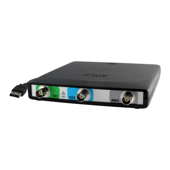
Page 31: Front Panel
Front panel Figure 7.1: Front panel CH1 and CH2 input connectors The CH1 and CH2 BNC connectors are the main inputs of the ac- quisition system. The outside of the BNC connectors is connected to the ground of the Handyscope HS5. Connecting the outside of the BNC connector to a potential other than ground will result in a short circuit that may damage the device under test, the Handy- scope HS5 and the computer. - Page 32 Chapter 7...
-
Page 33: Rear Panel
Rear panel Figure 8.1: Rear panel Power The Handyscope HS5 is powered through the USB. If the USB cannot supply enough power, it is possible to power the instru- ment externally. The Handyscope HS5 has two external power inputs located at the rear of the instrument: the dedicated power connector and a pin of the 9 pin D-sub extension connector. -
Page 34: Power Adapter
Note that the externally applied voltage should be higher than the USB voltage to relieve the USB port. 8.1.1 Power adapter The Handyscope HS5 comes with an external power adapter that can be connected to any mains power net that supplies 100 – 240 , 50 –... -
Page 35: Usb
The Handyscope HS5 is equipped with a USB 2.0 High speed (480 Mbit/s) interface with a fixed cable with type A plug. It will also work on a computer with a USB 1.1 interface, but will then operate at 12 Mbit/s. Extension Connector Figure 8.5: Extension connector A 9 pin female D-sub connector is available at the back of the... -
Page 36: Aux I/O
Pin 8, Power OUT, has the same potential as the Handyscope HS5 power supply. When the Handyscope HS5 is USB powered, it is at USB power level. When the Handyscope HS5 is externally powered, it is at the same level as the external power input. AUX I/O The Handyscope HS5 has two Auxiliary I/O connectors at the rear of the instrument. -
Page 37: Specifications
Specifications To achieve rated accuracy, allow the instrument to settle for 20 min- utes. When subjected to extreme temperatures, allow additional time for internal temperatures to stabilize. Because of temperature compensated calibration, the Handyscope HS5 will settle within specified accuracy regardless of the surrounding temperature. Acquisition system Number of input channels 2 analog... -
Page 38: Acquisition System (Continued)
Acquisition system (continued) Maximum sampling rate Depending on model Model 540, Model 530 8/12 bit, measuring one channel 500 MS/s 8/12 bit, measuring two channels 200 MS/s 14 bit 100 MS/s 16 bit 6.25 MS/s Model 220 8/12 bit, measuring one channel 200 MS/s 8/12 bit, measuring two channels 100 MS/s 14 bit... -
Page 39: Trigger System
Trigger system System Digital, 2 levels Source CH1, CH2, digital external, OR, generator start, generator new period, generator stop Trigger modes Rising edge, falling edge, any edge, inside window, outside window, enter window, exit window, pulse width Level adjustment 0 to 100% of full scale Hysteresis adjustment 0 to 100% of full scale Resolution... -
Page 40: Arbitrary Waveform Generator
Arbitrary Waveform Generator Output channel 1 analog, BNC DAC resolution 14 bit @ 240 MS/s Output range -12 to +12 V (open circuit) Amplitude Range 0.12 V, 1.2 V, 12 V (open circuit) Resolution 12 bit Accuracy 0.4% of range DC offset Range -12 V to +12 V (open circuit) - Page 41 Arbitrary Waveform Generator - continued Signal characteristics Sine Frequency range Depending on model Model 540 1 Hz to 40 MHz Model 530 1 Hz to 30 MHz Model 220 1 Hz to 20 MHz Model 110 1 Hz to 10 MHz Model 055 1 Hz to 5 MHz Amplitude flattness...
- Page 42 Arbitrary Waveform Generator - continued Signal characteristics - continued Noise Bandwidth (typical) 30 MHz Arbitrary Frequency range Depending on model Model 540, Model 530 1 Hz to 30 MHz Model 220 1 Hz to 20 MHz Model 110 1 Hz to 10 MHz Model 055 1 Hz to 5 MHz Pattern length...
-
Page 43: Power
Power Power From USB or external input Consumption , 500 mA max Power adapter External Input 110 to 240 V , 50 to 60 Hz 0.85 A Max., 50 VA to 80 VA Output 5.5 V , 2 A Dimension Height 30 mm / 1.2”... -
Page 44: System Requirements
9.10 System requirements PC I/O connection USB 1.1, USB 2.0 or newer Operating System Windows XP/Vista/7/8/10 32 and 64 bits 9.11 Environmental conditions Operating Ambient temperature 0 C to 55 C Relative humidity 10 to 90% non condensing Storage Ambient temperature -20 C to 70 C Relative humidity 5 to 95% non condensing... -
Page 45: Probes
9.13 Probes Model HP-9250 Bandwidth 6 MHz 1:10 250 MHz Rise time 58 ns 1:10 1.4 ns Input impedance 1 MΩ (oscilloscope impedance) 1:10 10 MΩ (incl. 1 MΩ oscilloscope impedance) Input capacitance 47 pF + oscilloscope capacitance 1:10 17 pF Compensation range 1:10 10 to 35 pF... - Page 46 Chapter 9...
- Page 47 If you have any suggestions and/or remarks regarding this manual, please contact: TiePie engineering Koperslagersstraaat 37 8601 WL SNEEK The Netherlands Tel.: +31 515 415 416 Fax: +31 515 418 819 E-mail: support@tiepie.nl Site: www.tiepie.com...