TiePie Handyscope HS4 DIFF-5MHz User Manual
Hide thumbs
Also See for Handyscope HS4 DIFF-5MHz:
- Programmer's manual (67 pages) ,
- Instrument manual (41 pages) ,
- User manual (32 pages)
Table of Contents
Advertisement
Quick Links
Advertisement
Table of Contents

Related Manuals for TiePie Handyscope HS4 DIFF-5MHz


Summary of Contents for TiePie Handyscope HS4 DIFF-5MHz
- Page 1 Handyscope HS4 DIFF User manual TiePie engineering...
- Page 2 Copyright ©2020 TiePie engineering. All rights reserved. Revision 2.27, February 2020 Despite the care taken for the compilation of this user man- ual, TiePie engineering can not be held responsible for any damage resulting from errors that may appear in this man- ual.
-
Page 3: Table Of Contents
Contents Safety Declaration of conformity Introduction Differential input ......3.1.1 Differential attenuators ....3.1.2 Differential test lead . - Page 4 7.1.1 USB power cable ..... . 7.1.2 Power adapter ......
- Page 5 Do not use the equipment if it does not operate properly. Have the equip- ment inspected by qualified service personal. If necessary, return the equip- ment to TiePie engineering for service and repair to ensure that safety fea- tures are maintained.
-
Page 7: Declaration Of Conformity
8601 WL Sneek The Netherlands EC Declaration of conformity We declare, on our own responsibility, that the product Handyscope HS4 DIFF-5MHz Handyscope HS4 DIFF-10MHz Handyscope HS4 DIFF-25MHz Handyscope HS4 DIFF-50MHz for which this declaration is valid, is in compliance with... - Page 8 Environmental considerations This section provides information about the environmental impact of the Handy- scope HS4 DIFF. End-of-life handling Production of the Handyscope HS4 DIFF required the extraction and use of natural resources. The equipment may contain substances that could be harmful to the environment or human health if improperly handled at the Handyscope HS4 DIFF’s end of life.
-
Page 9: Introduction
Introduction Before using the Handyscope HS4 DIFF first read chapter about safety. Many technicians investigate electrical signals. Though the measurement may not be electrical, the physical variable is often converted to an electrical signal, with a special transducer. Common transducers are accelerometers, pressure probes, current clamps and temperature probes. -
Page 10: Differential Input
Differential input Most oscilloscopes are equipped with standard, single ended inputs, which are referenced to ground. This means that one side of the input is always connected to ground and the other side to the point of interest in the circuit under test. Figure 3.1: Single ended input Therefore the voltage that is measured with an oscilloscope with standard, single ended inputs is always measured between that specific point and ground. -
Page 11: Differential Attenuators
Figure 3.2: Differential input A differential input is not referenced to ground, but both sides of the input are ”floating”. It is therefore possible to connect one side of the input to one point in the circuit and the other side of the input to the other point in the circuit and measure the voltage difference directly. - Page 12 Figure 3.4: Differential attenuator matches with differential input Standard oscilloscope probes and attenuators only attenuate one side of the sig- nal path. These are not suitable to be used with a differential input. Using these on a differential input will have a negative effect on the CMRR and will introduce measurement errors.
-
Page 13: Differential Test Lead
• do not apply excessive mechanical force to the attenuator in any direction (e.g. pulling the cable, using the attenuator as handle to carry the Handy- scope HS4 DIFF, etc.) 3.1.2 Differential test lead The Handyscope HS4 DIFF comes with a special differential test lead. This test lead is specially designed to ensure a good CMRR. -
Page 14: Sampling Rate
Figure 3.7: ”connecting” the samples Sampling rate The rate at which the samples are taken is called the sampling rate, the number of samples per second. A higher sampling rate corresponds to a shorter interval between the samples. As is visible in figure 3.8, with a higher sampling rate, the original signal can be reconstructed much better from the measured samples. - Page 15 Multiple of sampling rate 1250 Hz signal -1250 Hz signal -1000 -1000 + 1250 = 250 -1000 - 1250 = -2250 0 + 1250 = 1250 0 - 1250 = -1250 1000 1000 + 1250 = 2250 1000 - 1250 = -250 2000 2000 + 1250 = 3250 2000 - 1250 =...
-
Page 16: Digitizing
Digitizing When digitizing the samples, the voltage at each sample time is converted to a number. This is done by comparing the voltage with a number of levels. The re- sulting number is the number corresponding to the level that is closest to the voltage. - Page 17 When measuring DC signals, make sure to set the signal coupling of the input to DC. Introduction...
- Page 18 Chapter 3...
-
Page 19: Driver Installation
The driver setup program and measurement software can be found in the down- load section on TiePie engineering’s website. It is recommended to install the latest version of the software and USB driver from the website. This will guarantee the latest features are included. - Page 20 Figure 4.1: Driver install: step 1 When drivers were already installed, the install utility will remove them before in- stalling the new driver. To remove the old driver successfully, it is essential that the Handyscope HS4 DIFF is disconnected from the computer prior to starting the driver install utility.
- Page 21 Figure 4.3: Driver install: Finished Driver installation...
- Page 22 Chapter 4...
-
Page 23: Hardware Installation
When the Handyscope HS4 DIFF is plugged into a different USB port, some Win- dows versions will treat the Handyscope HS4 DIFF as different hardware and will install the drivers again for that port. This is controlled by Microsoft Windows and is not caused by TiePie engineering. Hardware installation... - Page 24 Chapter 5...
-
Page 25: Front Panel
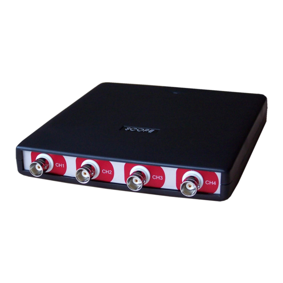
Front panel Figure 6.1: Front panel Channel input connectors The CH1 – CH4 BNC connectors are the main inputs of the acquisition system. The isolated BNC connectors are not connected to the ground of the Handyscope HS4 DIFF. Power indicator A power indicator is situated at the top cover of the instrument. - Page 26 Chapter 6...
-
Page 27: Rear Panel
Rear panel Figure 7.1: Rear panel Power The Handyscope HS4 DIFF is powered through the USB. If the USB cannot deliver enough power, it is possible to power the instrument externally. The Handyscope HS4 DIFF has two external power inputs located at the rear of the instrument: the dedicated power input and a pin of the extension connector. -
Page 28: Power Adapter
Figure 7.3: USB power cable One end of this cable can be connected to a second USB port on the computer, the other end can be plugged in the external power input at the rear of the instrument. The power for the instrument will be taken from two USB ports of the computer. The outside of the external power connector is connected to +5 V. -
Page 29: Extension Connector
Extension Connector Figure 7.4: Extension connector To connect to the Handyscope HS4 DIFF a 25 pin female D-sub connector is avail- able, containing the following signals: Description Description Ground Ground Reserved Ground External Power in DC Reserved Ground Ground +5V out, 10 mA max. Reserved Ext. - Page 30 Chapter 7...
-
Page 31: Specifications
Specifications Acquisition system Number of input channels 4 analog CH1, CH2, CH3, CH4 isolated BNC Type Differential Resolution 12, 14, 16 bit user selectable 0.3% of full scale ± 1 LSB Accuracy Ranges (full scale) ±200 mV ±400 mV ±800 mV ±2 V ±4 V ±8 V... -
Page 32: Trigger System
Trigger system System digital, 2 levels Source CH1, CH2, CH3, CH4, digital external, AND, OR Trigger modes rising slope, falling slope, inside window, outside window Level adjustment 0 to 100% of full scale Hysteresis adjustment 0 to 100% of full scale Resolution 0.024 % (12 bits) Pre trigger... -
Page 33: Environmental Conditions
Environmental conditions Operating ◦ ◦ Ambient temperature C to 55 Relative humidity 10 to 90% non condensing Storage ◦ ◦ Ambient temperature C to 70 Relative humidity 5 to 95% non condensing Certifications and Compliances CE mark compliance RoHS EN 55011:2016/A1:2017 EN 55022:2011/C1:2011 IEC 61000-6-1:2019 EN IEC 61000-6-3:2007/A1:2011/C11:2012... -
Page 34: Differential Attenuators
8.11 Differential attenuators Model TP-DA10 Attenuation 10 x, differential Bandwidth 25 MHz Input impedance 10 MΩ // 15 pF Maximum input voltage 300 V Input connector Female BNC Output connector Male BNC Dimensions Length 79 mm Diameter 19 mm Weight 30 g Suitable instrument Handyscope HS4 DIFF... - Page 35 If you have any suggestions and/or remarks regarding this manual, please contact: TiePie engineering Koperslagersstraat 37 8601 WL SNEEK The Netherlands Tel.: +31 515 415 416 Fax: +31 515 418 819 E-mail: support@tiepie.nl Site: www.tiepie.com...
- Page 36 TiePie engineering Handyscope HS4 DIFF instrument manual revision 2.27, February 2020...