
Related Manuals for Nortel 1600 Series

Summary of Contents for Nortel 1600 Series
- Page 1 Part No. 316860-D June 2006 4655 Great America Parkway Santa Clara, CA 95054 Installing the Ethernet Routing Switch 1600 Series Switch Software Release 2.1 *316860-D*...
- Page 2 In the interest of improving internal design, operational function, and/or reliability, Nortel Networks Inc. reserves the right to make changes to the products described in this document without notice. Nortel Networks Inc. does not assume any liability that may occur due to the use or application of the product(s) or circuit layout(s) described herein.
- Page 3 CE marking statement (Europe only) EN 55 022 statements This is to certify that the Nortel Ethernet Routing Switch 1600 Series are shielded against the generation of radio interference in accordance with the application of Council Directive 89/336/EEC. Conformity is declared by the application of EN 55 022 Class A (CISPR 22).
- Page 4 EN 55 024 statement This is to certify that the Nortel Ethernet Routing Switch 1600 Series are shielded against the susceptibility to radio interference in accordance with the application of Council Directive 89/336/EEC. Conformity is declared by the application of EN 55 024 (CISPR 24).
- Page 5 EN 60 950 statement This is to certify that the Nortel Ethernet Routing Switch 1600 Series are in compliance with the requirements of EN 60 950 in accordance with the Low Voltage Directive. Additional national differences for all European Union countries have been evaluated for compliance.
- Page 6 Denan statement (Japan/Nippon only) 316860-D...
- Page 7 30 days of purchase to obtain a credit for the full purchase price. “Software” is owned or licensed by Nortel Networks, its parent or one of its subsidiaries or affiliates, and is copyrighted and licensed, not sold. Software consists of machine-readable instructions, its components, data, audio-visual content (such as images, text, recordings or pictures) and related licensed materials including all whole or partial copies.
- Page 8 48 C.F.R. 227.7202 (for Odd entities). b. Customer may terminate the license at any time. Nortel Networks may terminate the license if Customer fails to comply with the terms and conditions of this license. In either event, upon termination, Customer must either return the Software to Nortel Networks or certify its destruction.
-
Page 9: Table Of Contents
Chapter 1: Introducing the 1600 Series Switch..... . 21 Ethernet Routing Switch 1600 Series models ....... 22 Ethernet Routing Switch 1648T . - Page 10 Appendix A: Technical specifications ......43 Ethernet Routing Switch 1600 Series switches ......43 Physical specifications .
- Page 11 Fiber Optic Cable Insertion and Removal ......42 Installing the Ethernet Routing Switch 1600 Series Switch...
- Page 12 316860-D...
- Page 13 LED problem indicators ........35 Installing the Ethernet Routing Switch 1600 Series Switch...
- Page 14 316860-D...
-
Page 15: Preface
Ethernet Routing Switch 1648T 48 10/100, plus 4 SFP GBICs, which provides small edge concentration The Ethernet Routing Switch 1600 Series Layer 3 routing switch can reside in the wiring closet (1648T) and in the data center or network core (1612G and 1624G). -
Page 16: Before You Begin
Before You Begin This guide is intended for qualified service personnel who are installing the Ethernet Routing Switch 1600 Series switch for the first time. A qualified service person should have appropriate technical training and experience and be aware of the hazards involved in installing and replacing customer-replaceable units. - Page 17 Preface 17 The following list outlines the documenation in the 1600 Series suite: • Configuring QoS and Filters using the CLI and Device Manager (Part Number 321822-A) • CLI Command Line Reference for the Ethernet Routing Switch 1600 Series Switch (Part Number 316862-D) •...
-
Page 18: Technical Documentation
The Adobe Reader can be downloaded from the Adobe web site. How to Get Help If a service contract for the Nortel product was purchased from a distributor or authorized reseller, contact the technical support staff for that distributor or reseller for assistance. - Page 19 Preface 19 An Express Routing Code (ERC) is available for many Nortel products and services. When you use an ERC, your call is routed to a technical support person who specializes in supporting that product or service. To locate the ERC for your product or service, go to http://www.nortel.com/help and follow these links:...
- Page 20 Preface 316860-D...
-
Page 21: Chapter 1: Introducing The 1600 Series Switch
Chapter 1 Introducing the 1600 Series Switch This chapter introduces the various 1600 Series switch models and discusses their components. Specifically, the chapter includes the following topics: Topic Page Ethernet Routing Switch 1600 Series models Enclosure Power Supplies Installing the Ethernet Routing Switch1600 Series Switch... -
Page 22: Ethernet Routing Switch 1600 Series Models
22 Chapter 1 Introducing the 1600 Series Switch Ethernet Routing Switch 1600 Series models The 1600 Series switches are available in the following three models: • Ethernet Routing Switch 1648T • Ethernet Routing Switch 1624G • Ethernet Routing Switch 1612G Each of these models are explained in more detail in the sections that follow. -
Page 23: Ethernet Routing Switch 1624G
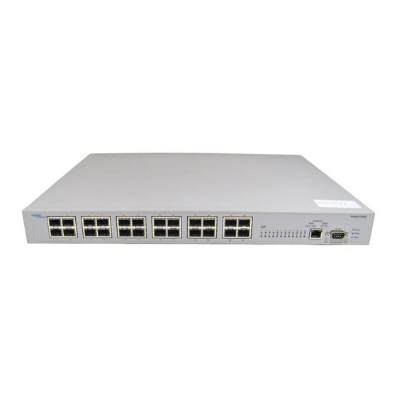
Chapter 1 Introducing the 1600 Series Switch 23 The LEDs on the front panel indicate the status of each of the following: • 48 Fast Ethernet ports • four Gigabit Ethernet SFP modules • main and redundant power supplies Generally, a lit LED indicates a functioning power supply or port. A flashing LED indicates either activity on an Ethernet port, or a failure of one of the two built-in AC power supplies. -
Page 24: Ethernet Routing Switch 1612G
Ethernet port, or a failure of one of the two built-in AC power supplies. Enclosure Each 1600 Series switch consists of a standard 19” rack-mountable, sheet metal enclosure. Mounting ears are included in the switch’s packaging to allow mounting the switch in a standard 19” electronic equipment rack. -
Page 25: Power Supplies
Chapter 1 Introducing the 1600 Series Switch 25 Power Supplies The 1600 Series switches include two internal power supplies. These units have two AC receptacles for AC power cords and two power on/off switches to control (Figure 4 on page 25). - Page 26 26 Chapter 1 Introducing the 1600 Series Switch 316860-D...
-
Page 27: Chapter 2: Unpacking And Setting Up The Switch
Two AC power cords (if ordered with appropriate country kit) • A CD containing the software and documentation for the switch If any item is missing or damaged, please contact your local Nortel reseller for replacement. Installing the Switch When choosing a place to install the 1600 Series switch, use the following... -
Page 28: Installing The Switch On A Desktop Or Shelf
Figure 5 Rubber Feet and Mounting Bracket Attachment Points Installing the Switch in a Rack The 1600 Series switches can be installed in a standard 19-inch electronic equipment rack or cabinet. Along with the required screws, two mounting brackets are included in the switch’s packaging. -
Page 29: Powering Up The Switch
19-inch rack should be supplied by the rack manufacturer. Powering up the Switch The 1600 Series switch can be used with an AC power supply of 100–240 VAC, 50–60 Hz. The power switch is located at the rear of the unit adjacent to the AC power connector and the system fan. - Page 30 30 Chapter 2 Unpacking and Setting up the Switch • Depending on the transmission speed, the 100M LED remains on. 316860-D...
-
Page 31: Chapter 3: Understanding The Leds
LED Problem Indicators Status Information The Ethernet Routing Switch 1600 Series switches have LEDs on their front panels that indicate the status of the power supply, the secondary power supply, the link between a port and a remote network device, and the presence of activity on that link. -
Page 32: Power And Rpsu Leds
The Power and RPSU LEDs work in concert to display the status of the two 1600 Series switch power supplies. Note: The 1600 Series switches have on/off switches on the rear panel... -
Page 33: Status Led
LEDs. This circumstance can also arise if you connect the switch to the main AC circuit with both the AC power switches on the rear panel of the 1600 Series switches in the Off position. Status LED Table 2 describes the Status LED and its behavior. -
Page 34: Fast Ethernet Port Link/Act Leds
34 Chapter 3 Understanding the LEDs Fast Ethernet Port Link/Act LEDs Each Fast Ethernet port on the 1600 Series switches has a two color LED that displays the status of the link between the switch and a remote network device... -
Page 35: Led Problem Indicators
Chapter 3 Understanding the LEDs 35 LED Problem Indicators Table 4 lists possible problems indicated by the LEDs on the 1600 Series switches and suggests corrective action. Table 4 LED problem indicators Symptom Probable cause Corrective action The Link/Activity LED for a... - Page 36 36 Chapter 3 Understanding the LEDs 316860-D...
-
Page 37: Chapter 4: Using The Sfp Fiber Optic Modules
Chapter 4 Using the SFP Fiber Optic Modules The Ethernet Routing Switch 1648T provides 4 SFP slots, while the 1624G has 24 slots and the 1612G has 12 slots. These slots accept SFP fiber optic modules that operate at 1000 Mbps in full-duplex mode. They can connect fiber optic cables to other network devices. -
Page 38: Inserting Sfp Modules
Use the correct fiber optic cable type to ensure the proper performance of the fiber optic network link. To install an SFP module: Insert the module into an empty slot on the 1600 Series switch. Figure 8 on page 39 shows the module being inserted in the 1648T model. -
Page 39: Removing Sfp Modules
Chapter 4 Using the SFP Fiber Optic Modules 39 the SFP module is properly aligned with the slot, and that the module’s rear electrical connector is facing down for the two SFP slots on top of the group of four. b the electrical connectors on the SFP fiber optic module are facing up for the two SFP slots on the bottom of the group of four. -
Page 40: Figure 9 Lever-Type Sfp Fiber Optic Module Removal
40 Chapter 4 Using the SFP Fiber Optic Modules Note that you cannot remove this type of module without first disconnecting the fiber optic cable from the module because the fiber optic cables block the movement of the lever. Figure 9 shows the removal of a lever-type SFP module from the Ethernet Routing Switch 1648T. -
Page 41: Inserting And Removing An Sfp Module Fiber Optic Cable
Chapter 4 Using the SFP Fiber Optic Modules 41 Figure 10 Slider-type SFP Fiber Optic Module Removal Caution: Ensure that the connector on the fiber optic cable is properly aligned. You can insert this connector one way only; if it does not fit, do not force it. -
Page 42: Figure 11 Fiber Optic Cable Insertion And Removal
42 Chapter 4 Using the SFP Fiber Optic Modules Figure 11 Fiber Optic Cable Insertion and Removal 316860-D... -
Page 43: Appendix A: Technical Specifications
This appendix lists the technical specifications for the Ethernet Routing Switch 1600 Series switches. Ethernet Routing Switch 1600 Series switches The physical, environmental, and AC power supply specifications for the three 1600 Series switches are listed in the sections that follow. Physical specifications Height: 4.4 cm (1.73 inches) -
Page 44: Environmental Specifications
A TTL logic signal is used to signal the failure of one of the two power supplies built-in to the 1600 Series switches. This signal will react to a power supply failure at least 1 ms before the loss of output voltage regulation. -
Page 45: System-Level Regulatory Requirements
Technical specifications 45 EMI standards: FCC docket 20780 curve “B”, EN 55 022 “B”, EN6100-3-2 EMS standards: EN61000-4-2, 6KV contact, 8KV air EN61000-4-3, 10V/m criteria A EN61000-4-4, 2KV criteria A EN61000-4-5, 2KV criteria A EN61000-4-6, 2KV criteria A EN61000-4-11 - 30% dip 10ms criteria B - 60% dip 100ms criteria C - 95% dip 5000ms criteria C System-level regulatory requirements... -
Page 46: General Specifications
Technical specifications General specifications General specifications including supported standards, data rate and encoding, performance, address database sizes, and Mean Time Between Failure (MTBF) are listed in the sections that follow. Standards supported IEEE Std 802.3, 1998 Clause 4 Media Access Control CSMA/CD IEEE Std 802.3, 1998 Clause 14 10Base T New IEEE Std 802.3, 1998 Clause 21 100Base T ANSI/IEEE Std 802.1D, 1998 Media Access Control (MAC) Bridges... -
Page 47: Performance Specifications (64-Byte Packets)
Technical specifications 47 Performance specifications (64-byte packets) Aggregate throughput: Switched forwarding rates: For 10 Mb/s: 14,880 pps maximum For 100 Mb/s: 14810 pps maximum For 1000 Mb/s: 1,488,000 pps maximum Latency: Address database size Addressing: 48-bit MAC address Frame Length: 64 to 1518 bytes (IEEE 802.1Q (Untagged) 64 to 1522 bytes (IEEE 802.1Q Tagged) Installing the Ethernet Routing Switch1600 Series Switch... -
Page 48: Sfp Fiber Optic Module
Technical specifications SFP Fiber Optic Module SFP fiber optic module transmitter electrical and optical, receiver electrical and optical, and regulatory compliance specifications are detailed in the sections that follow. General specifications Data Rate: 1.0625 Gb/s, typical 1.0 Gb/s, minimum Bit Error Rate: 10-12, maximum, 1.25 Gb/s using PRBS-1 Fiber length 50/125 µm MMF: 550 m... -
Page 49: Receiver Electrical Characteristics
Technical specifications 49 Receiver electrical characteristics Single ended data output swing: 185 to 600 mV Data output rise time: 350 ps, maximum Data output fall time: 350 ps, maximum Receiver optical characteristics Sensitivity: -18 dBm, minimum Electrical 3 dB cutoff frequency: 1500 MHz Optical center wavelength: 770 to 860 nm... - Page 50 Technical specifications 316860-D...
-
Page 51: Appendix B: Translation Of Safety Messages
Appendix B Translation of Safety Messages This section provides translations of the Caution, Danger, and Warning messages that appear within this document. Caution: This device is a Class A product. In a domestic environment, this device can cause radio interference, in which case the user may be required to take appropriate measures. - Page 52 Translation of Safety Messages 316860-D...
- Page 53 Translation of Safety Messages 53 Caution: Do not set a Nortel Ethernet Routing Switch Power Supply 15 (RPS 15) or Ethernet Switch Power Supply Unit 10 on top of an [Product Name (short)]. The Power Supply Unit 10 weighs approximately 100 pounds (45 kg) and the RPS 15 weighs approximately 40 pounds (17 kg).
- Page 54 Translation of Safety Messages Caution: When mounting this device in a rack, do not stack units directly on top of one another in the rack. Each unit must be secured to the rack with appropriate mounting brackets. Mounting brackets are not designed to support multiple units. Achtung: Wenn diese Einheit in einem Rack montiert wird, muß...
- Page 55 Translation of Safety Messages 55 Danger: Use only power cords that have a grounding path. Without a proper ground, a person who touches the switch is in danger of receiving an electrical shock. Lack of a grounding path to the switch may result in excessive emissions. Vorsicht: Verwenden Sie nur Netzkabel mit Schutzerdung.
- Page 56 Translation of Safety Messages Warning: Disconnecting the AC power cord is the only way to turn off AC power to this device. Always connect the AC power cord in a location that can be reached quickly and safely in case of an emergency. Warnung: Das Gerät kann nur durch Ziehen des Netzsteckers ausgeschaltet werden.
- Page 57 Translation of Safety Messages 57 Warning: Fiber optic equipment can emit laser or infrared light that can injure your eyes. Never look into an optical fiber or connector port. Always assume that fiber optic cables are connected to a light source. Vorsicht: Glasfaserkomponenten können Laserlicht bzw.
- Page 58 Translation of Safety Messages 316860-D...
-
Page 59: Index
1600 switch 27 receiver optical characteristics 49 regulatory compliance 49 installing the 1600 Series switch specifications 48 in a rack 28 transmitter electrical characteristics 48 on a desktop of shelf 28 Installing the Ethernet Routing Switch 1600 Series Switch... - Page 60 45 POST routine 32 LEDs power supplies, 1600 Series switch 25 1612G front panel status indicators 24 powering up the 1600 Series switch 29 1624G front panel product support 18 status indicators 23 1648T front panel status indicators 23...