Subaru EA190V Service Manual
Hide thumbs
Also See for EA190V:
- Instructions for use manual (74 pages) ,
- Service manual (52 pages) ,
- Product manual (20 pages)
Table of Contents
Advertisement
Advertisement
Table of Contents

Related Manuals for Subaru EA190V


Summary of Contents for Subaru EA190V
- Page 1 EA190V SERVICE MANUAL...
- Page 3 This manual contains information how to routine maintain and how to do troubleshooting. Keep this owner’s manual handy, so you can refer to it at any time. This service manual describes correct method of the maintaining this equipment. As a result of this disregard for the our rules caused by person casualty and equipment damaged, our company does not assume any responsibility NOTICE:...
-
Page 4: Table Of Contents
CONTENT 1. INTRODUCTION 1. PARTS DESCRIPTION..............................5 1-1 Part description ..............................5 1-1-1 Feature ..............................6 1-1-2 Model & serial number..........................6 1-2 Specification ..............................6 1-3 Service limit..............................7 II. DIMENSION AND TORQUE ..........................8 2-1 Engine dimension .............................8 2-1-1 Appearance dimension...........................8 2-1-2 Installation hole position ........................9 2-1-3 P.T.O dimension figure ......................... -
Page 5: Parts Description
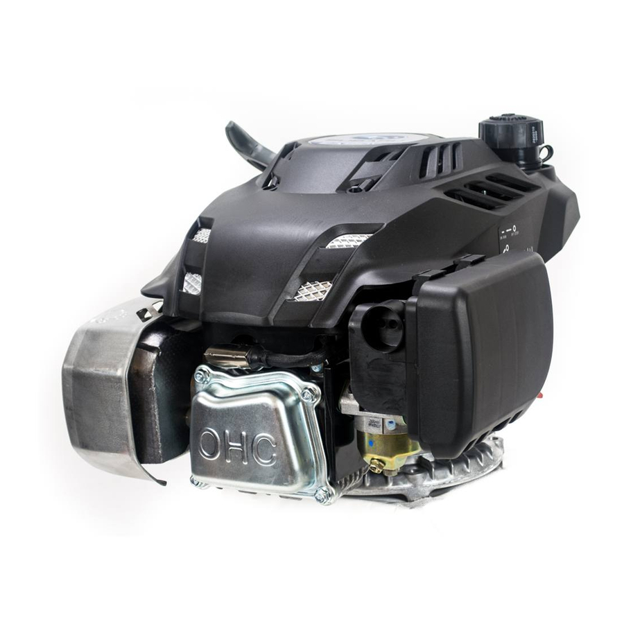
1. PARTS DESCRIPTION 1-1 Part description 1-1-1 Feature Oil dipstick Spark plug Drain plug Muffler Starting lever Air cleaner Fuel tank cap Fuel tank Engine switch... -
Page 6: Model & Serial Number
1-1-2 Model & serial number Engine model Serial number 1-2 Specification Model EA190 Specification L×W×H 425×360×290mm (not including crankshaft output terminal) Dry Weight 11.5 or 14.5kg Engine Type single cylinder horizontal,4-stroke,(OHC) Displacement 189ml Bore × Stroke 68mm×52mm Theoretical Maximum Power 3.72kW/3,600r/min Recommended Using Power... -
Page 7: Service Limit
1-3 Service limit UNIT:mm Parts Item Standard Service limit Maximum speed (No load) 3800±100rpm Engine Cylinder compression 1.15Mpa at 1200rpm Cylinder head Sleeve I.D 68.00-68.02 68.160 Cylinder head War page 0-0.05 0.100 Skirt O.D. 67.989-67.971 67.850 Piston – to cylinder clearance 0.011-0.049 0.120 Piston... -
Page 8: Dimension And Torque
II. DIMENSION AND TORQUE 2-1 Engine dimension 2-1-1 Appearance dimension... -
Page 9: Installation Hole Position
2-1-2 Installation hole position 2-1-3 P.T.O dimension figure... -
Page 10: Torque Value
2-2 Torque value Item Specification Performance class Torque value (N·m) Cylinder head M8×65 10.9 26±2 Crankcase cover M6×30 10±2 Oil drain plug M10×15 22±2 Connecting rod M6×35 10.9 13±1 Valve locking nut 6±2 Governor gear M6×16 10±2 78±4 (iron flywheel ) Flywheel 64±4 (aluminum flywheel) -
Page 11: Standard Torque Value
2-3 Standard torque value Fasteners Thread dia.(mm) Torque value(N·m) 5mm bolt, nut 4.5-6 8-12 6mm bolt、nut 8mm bolt、nut 18-25 10mm bolt、nut 29-34 49-59 12mm bolt、nut 4mm screw 1.5-2.6 5mm screw 3.5-5 6mm screw 7-11 Bolt and nut 5mm flange bolt 3.6-6.9 6mm screw 7-11... -
Page 12: Maintenance
III. MAINTENANCE 3-1. Maintenance schedule Good maintenance is essential for safe, economical, and trouble-free operation. It will also help reduce air pollution. Exhaust gas contains poisonous carbon monoxide. Shut off the engine before performing any maintenance. If the engine must be run, make sure the area is well ventilated. Periodic maintenance and adjustment is necessary to keep the generator in good operating condition. -
Page 13: Change Oil
3-2 Change oil ·Change oil NOTICE: Drain the engine oil rapidly and completely out when the engine is hot. (1) Remove the oil dipstick, drain plug and washer and tilt the Washer engine to drain engine oil thoroughly. (2) Reinstall the drain plug and washer screw in it securely by hand. -
Page 14: Air Cleaner
3-3 AIR CLEANER NOTICE: A dirty air cleaner will restrict air flow to the carburetor. To prevent carburetor malfunction, clean the air cleaner each 50 hours (or three month) and service the air cleaner regularly. Service more frequently when operating the generator in extremely dusty areas. Using gasoline or flammable solvent to clean the filter element can cause a fire or explosion. -
Page 15: Fuel Check
3-4-2 Fuel check 1) Remove the fuel tank cap and check fuel level. pper limit 3/4position of the fuel tank ( ) 2) If the level is too low, refuel the tank. Remember adding fuel, but, not over the fuel upper level. Fuel tank Fuel WARNING :... -
Page 16: Spark Plug Service
3-5 Spark Plug Service Remove the spark plug cap. Clear away dirt around the spark plug base; Use the plug wrench to remove the spark plug; Visually inspect the spark plug if the insulator is cracked, if cracked, replace with new the spark plug, if deposit around the electrode, Remove carbon or other deposits with a stiff wire brush;... -
Page 17: Valve Clearance Adjustment
3-6 Valve clearance adjustment Keep the clearance between engine valve rod end and driving parts for avoiding heat expanding and cold shrinking to effect engine performance. If the valve is too big, it can result in exhausting unsmooth, effecting engine performance and increasing engine noise (valve abnormal), if the valve is too small, the valve will close untighten to make the engine operating abnormal and drain valve operating face burn. - Page 18 (4) If adjustment is necessary, proceed as follows: a) Hold valve adjusting bolt with tongs and loosen the valve lock nut b) Turn valve adjusting bolt to obtain the specified clearance. c) Fix the valve adjusting bolt with tongs, then fix the valve lock nut with spanner. d) Recheck valve clearance after tightening the valve lock nut——torque value :6±2N.m e) Set the new gasket aligning the projection of the new gaskets with the projection of the cylinder head;...
-
Page 19: Governor Adjusting
3-7 Governor adjusting ● Governor adjusting: (1) Dismount the air cleaner (2) Loosen the nut M6. Be sure that the carburetor throttle valve is fully open (3) Rotate the governor arm shaft fully to the right (governor fully open position) to bottom by pressing governor support, and retighten the nut., torque value: 10N.m (4) Check to see that the governor support and throttle valve move freely. -
Page 20: Setting The Timing Chain
3-8 Setting the timing chain ・Align the timing mark on the crankshaft sprocket with the mark plate of the timing chain. ・Align the timing mark hole on the camshaft sprocket with the mark plate of the opposite end of the timing chain. -
Page 21: Disassembling And Servicing
IV. DISASSEMBLING AND SERVICING 4-1 Troubleshooting 4-1-1 starting difficult TROUBLE CAUSE REMEDY There is no enough fuel in fuel Fill fuel, open fuel cock. tank and fuel cock is closed. Air vent in the fuel filler cap is Dredge air vent. clogged Improper or clogged main oil Readjust or clean, blow to get... -
Page 22: Power Lack
● Spark plug testing · Make sure there is no spilled fuel outside the engine and that the spark plug isn’t dipped with fuel. · To prevent fire, keep sparks far away from the spark plug mounting hole. · When testing the spark plug, never hold the high tension line of the spark plug and spark plug cap with wet hand. -
Page 23: Speed Unstable
● Cylinder pressure check · Drain the gasoline in the fuel tank out. · Drain the gasoline by loosening the oil drain bolt of the carburetor · Remove the spark plug cap and spark plug and install the cylinder pressure meter. ·... -
Page 24: Unable Igniting
4-1-4 Unable igniting TROUBLE CAUSE REMEDY Fuel is finished Refill fuel Carburetor is clogged Check fuel line and dredge Fuel supply Float is leaking Repair system Dismantle float chamber and clean or Needle valve is sticked replace needle valve. Spark plug is punctured, or Replace spark plug short-circuited by carbon deposit Unable... -
Page 25: Abnormal Sound
4-1-6 Abnormal sound TROUBLE CAUSE REMEDY Piston, piston ring or cylinder is worn Replace the worn part Connection rod or piston pin and piston pin Replace the worn part hole are worn Beating sound Crankshaft main neck is worn Replace bearing Piston ring is broken Replace piston ring Too much carbon deposit in combusting... -
Page 26: Preparation Of Servicing
4-2 Preparation of servicing 4-2-1 Safety precautions WARNING: Indicate a possibility of invalid warranty and personal or equipment damage if instructions are not followed. Please pay special attention to the following: 1) Strictly set the engine according to the regulated power on the nameplate. Do not overload, overrun the engine or run it with low load and at low speed in a long time. -
Page 27: Engine
4-3 Engine 4-3-1 Recoil starter /housing Disassembly: Description Description Description Hex. Flange nutM6 Return spring Starter rope Recoil starter Drive cam Starter case Compression Starting rope grip Stud M6X80 spring Rope guide assy. Washer Stud M6X68 Cross recessed pan head Starter coil spring Drive guide screw M5×20... -
Page 28: Fuel Tank
4-3-2 Fuel tank ● Disassembly/reassembly The fuel tank does not require general maintenance, but, sometimes the dusts and vapor will trouble the fuel system, so that, periodically washing it with lubrication oil and gasoline is required. WARING: Don’t smoke and use fire near the flammable solvent. Clean/installation ●... -
Page 29: Ignition Coil/Flywheel
4-3-3 Ignition coil/flywheel Description Description Flywheel nut Hex. Flange bolt-big series –B class(M6×25) Starting cup Ignition coil Impeller Ignition coil stop wire Flywheel assy. Clip ● Ignition coil NOTICE: Check high tension line insulator for cracked, replace if necessary. Assembly: 1) Disassemble engine housing, fuel tank and recoil starter in order. - Page 30 Check the ignition coil (Primary side) Measure the resistance of the primary coil by attaching one ohmmeter lead to the ignition coil’s primary terminal while touching the other tester lead to the iron core Primary side resistance value:1.0 -1.5Ω (Secondar y side) Measure the resistance of the secondary side of the coil with the spark plug cap removed, touching one test lead to the high tension cord while touching the other tester lead to the coil’s iron core.
- Page 31 Assembly: a) Clean the tapered part of dirt, oil grease and other foreign material before installation. Be sure that there is no washer and other foreign material on the magnetic part. b) Set the key in the key groove. c) Install the flywheel over the crankshaft. NOTICE: The flywheel may push the key out of its slot, check after assembling.
-
Page 32: Muffler
4-3-4 Muffler Stud M8×109 Gasket Hex. flange nut M8 Muffler Muffler housing Disassembly/reassembly: The muffler can produce carbon deposits in the long time operation and seriously trouble the exhaust system. To get the best performance, the muffler must be periodically removed the carbon deposits. Lightly tap the muffler and blow it with compressed air in cleaning carbon deposits. -
Page 33: Air Cleaner
4-3-5 Air cleaner Air cleaner shell Nut M6 Air cleaner Air cleaner seat element Paper Element Urethane Foam Element Disassembly/assembly: Disassemble the air cleaner as shown on the above figure. NOTICE ・Check for damage of the air cleaner gasket before reassembling. ・If necessary, please replace and pay attention to assembling direction, viewing from the air cleaner side. -
Page 34: Carburetor
4-3-6 Carburetor At high altitude, the standard carburetor air-fuel mixture will be excessively rich. Output power will decrease, and fuel consumption will increase. Engine performance can be improved by installing a smaller diameter main fuel jet in the carburetor and readjusting the pilot screw. - Page 35 Disassembly/reassembly: Fist disassemble air cleaner, and disassemble the carburetor as shown on the above figure. · Before reassembling, check the carburetor thermal gasket, carburetor gasket, and air cleaner gasket for damaged, please replace it if necessary. Please pay attention to assembling direction. ●...
- Page 36 Reassembly: (1) Check the float valve, float seat and float spring for wear. Float valve Float valve seat Worn Normal (2) Clean with compressed air before reassembling Main jet (3) Clean with compressed air before reassembling Main nozzle...
-
Page 37: Throttle Control
4-3-7 Throttle control Returning spring (hook the left end Governor lever(insert the into the throttle shaft small hole left eng into throttle valve Choke lever (hook the left shaft hole) end into the choke shaft hole. Governor support Lever rubber sleeve Bolt M6×12 Hex. -
Page 38: Cylinder Head/Valve Train
4-3-8 Cylinder head/valve train Exhaust valve Before Spark plug: Clean and adjust Cylinder head : Before installation, Dowel —A type spark plug before installation installation, remove remove any carbon deposits from ( Φ10×14 ) the combustion chamber, check carbon deposits and retainer contact measure... - Page 39 (2) Valve spring free length Measure the free length of the valve springs. If out of the standard or service limit, Please replace the spring. Standard Service limit 30.5mm 28.5mm (3) Valve Guide Inspection: a) Inspect the valve guide for smooth, scratch and damaged in the inner surface, and matching between the valve guide and cylinder cover for fastness.
- Page 40 Reamer: For best results, be sure the cylinder head is at room temperature before reaming valve guides. Valve guide Coat the reamer and valve guide with cutting oil. Rotate the reamer reamer clockwise through the valve guide for the full length of the reamer. ...
- Page 41 Tool:Valve seat cutter IN valve:32° Cutter holder EN valve:32° IN valve:45° EX valve:45° d) Use the 32°-45°cutters to narrow and adjust the valve seat so that it contacts the middle of the valve face. ・The 32°cutter removes material from the top edge (contact too high).
-
Page 42: Crankcase Cover/Governor Gear
4-3-9 Crankcase cover/governor gear Description Description Gasket Governor gear Dowel-A type Governor flyweight Oil seal Φ27×Φ42×7 Flyweight spindle Drain plug Spindle clip Washer (Φ10×Φ15.8×1.5) Spacer Crankcase cover Governor slider Bolt (M6×30) Washer (Φ37×Φ27.4×1) Bolt (M6×16) NOTICE · Don’t reuse the crankcase gasket. ·... -
Page 43: Crankshaft/Piston/Crankcase
4-3-10 Crankshaft/piston/crankcase Description Description Description Crankcase assy. Gasket Piston Oil dipstick Breath piece assy. Clip Seal ring Gasket Oil dipstick Flat washer-A class Connecting rod Connecting rod Governor arm Bolt (M6×16) body Connecting rod Lower cover Oil sealΦ6×Φ11×4 cover Deep groove ball Connecting rod Split pin bearing... - Page 44 Disassembly/reassembly: 120° Maker mark (1) Reassembly: a) Piston ring • Install with the maker mark facing upward as Top ring shown. “ ↑ ” Mark • Do not interchange the top ring and the second ring (top ring with chrome plated) Second ring •...
- Page 45 ) Oil seal : ・Apply oil to the circumference of a oil seal. ・Drive the oil seal in the cylinder barrel using following tool. Driver handle Retainer assembler Tools Driver handle, Retainer assembler : ・Apply the lubrication oil on, after reassembling. Oil seal Piston :...
- Page 46 c) Piston-cylinder clearance Difference between cylinder maximum diameter and piston skirt should be considered as piston-cylinder clearance. Check with piston converting in the cylinder, and inserting feeler between piston skirt bearing face and wall, then pull the feeler out, if feeling resistance and smoothly out, the thickness of the feeler shall be considered as piston-cylinder clearance.
- Page 47 (3)Check connecting rod If connecting rod bending, twisting or big end shaft bush and small end outer ring movement or crack on one side, should be rejected and replaced with new one. a) Check small end diameter If out of the standard or exceed service limit, replace the connecting rod. Standard Service limit 16.005-16.021mm...
- Page 48 ・Visually inspect camshaft face and camshaft height for damaged, and camshaft and bearing for loosening and wearing, replace as required. ・Check camshaft for height dimension. If out of the service limit, replace the camshaft. Standard Service limit IN lifter 23.98mm 23.730mm EX lifter 27.88 mm...
-
Page 49: Electric Diagram
4-4 Electric diagram Engine switch Engine switch 汽 油 机 开关 Black Spark plug Ignition coil... - Page 52 ISSUE EMD-ES7175 September 2015, Revised...