Subaru EA190V Service Manual
Hide thumbs
Also See for EA190V:
- Instructions for use manual (74 pages) ,
- Service manual (52 pages) ,
- Product manual (20 pages)
Table of Contents
Advertisement
Advertisement
Table of Contents

Related Manuals for Subaru EA190V


Summary of Contents for Subaru EA190V
- Page 1 EA190V SERVICE MANUAL...
- Page 2 This manual contains information on how to routine maintain and how to do troubleshooting. Keep service manual handy, so you can refer to it at any time. This service manual describes correct methods of maintaining this engine. As a result of person casualty and equipment damaged caused by the disregard for the rules, our company does not assume any responsibility.
-
Page 3: Table Of Contents
I. PARTS DESCRIPTION...............................1 1-1 Part description .................................1 1-1-1 Feature ................................1 1-1-2 Model & serial number..........................1 1-2 Specification ................................2 1-3 Service limit................................3 II. DIMENSION AND TORQUE ............................4 2-1 Engine dimension ..............................4 2-1-1 Appearance dimension...........................4 2-1-2 Installation hole position ..........................5 2-1-3 P.T.O dimension figure ..........................5 2-2 Torque value ................................6 2-3 Standard torque value ...............................7 2-4 Important bolt torque value............................7... -
Page 4: Parts Description
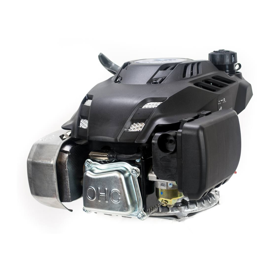
I. PARTS DESCRIPTION 1-1 Part description 1-1-1 Feature Oil dipstick Spark plug Muffler Drain plug Starter handle Air cleaner Fuel tank cap Fuel tank Engine stop switch Choke Fuel Valve 1-1-2 Model & serial number Engine model Serial number... -
Page 5: Specification
1-2 Specification Model EA190 Specification L×W×H(not including crankshaft output 425×360×290mm terminal) Dry Weight 14kg (iron flywheel) or 13kg (aluminum flywheel) Engine Type Single cylinder vertical,4-stroke,(OHC) Displacement 189ml Bore × Stroke 68mm×52mm Theoretical Maximum Power 3.72kW/3,600r/min Recommended Using Power 3.5 kW/3,400r/min Maximum Torque 11.2N·m /2,500r/min Fuel Consumption... -
Page 6: Service Limit
1-3 Service limit UNIT:mm Parts Item Standard Service limit Maximum speed (No load) 3800±100rpm 3650/4000- Engine Cylinder compression 1.15Mpa at 1200rpm Cylinder head Sleeve I.D 68.00-68.02 68.160 Cylinder head Flatness 0-0.05 0.100 Skirt O.D. 67.971-67.989 67.850 Piston – to cylinder clearance 0.011-0.049 0.120 Piston... -
Page 7: Dimension And Torque
II. DIMENSION AND TORQUE 2-1 Engine dimension 2-1-1 Appearance dimension... -
Page 8: Installation Hole Position
2-1-2 Installation hole position 2-1-3 P.T.O dimension figure... -
Page 9: Torque Value
2-2 Torque value Item Specification Performance class Torque value(N·m ) Cylinder head M8×65 10.9 28±2 Crankcase cover M6×30 10±1 Oil drain plug M10×15 22±2 Connecting rod M6×35 10.9 13±1 Valve locking nut 8±1 Governor gear M6×16 10±2 M14 (iron flywheel) 78±4 Flywheel M14 (aluminum... -
Page 10: Standard Torque Value
2-3 Standard torque value Fasteners Thread dia.(mm) Torque value(N·m) 5mm bolt, nut 4.5-6 6mm bolt, nut 8-12 8mm bolt, nut 18-25 10mm bolt, nut 29-34 12mm bolt, nut 49-59 4mm screw 1.5-2.6 5mm screw 3.5-5 Bolt and nut 6mm screw 7-11 5mm flange bolt 3.6-6.9... -
Page 11: Maintenance
III. MAINTENANCE 3-1. Maintenance schedule Good maintenance is essential for safe, economical, and trouble-free operation. It will also help reduce air pollution. Exhaust gas contains poisonous carbon monoxide. Shut off the engine before performing any maintenance. If the engine must be run, make sure the area is well ventilated. Periodic maintenance and adjustment is necessary to keep the engine in good operating condition. -
Page 12: Change Oil
3-2 Change oil ·change oil NOTICE: Drain the engine oil rapidly and completely out when the engine is hot. Washer (1)Remove the drain plug and washer and tilt the engine to drain engine oil thoroughly. (2)Reinstall the drain plug and washer into securely by hand. (3)... -
Page 13: Air Cleaner
3-3 AIR CLEANER NOTICE: A dirty air cleaner will restrict air flow to the carburetor. To prevent carburetor malfunction, clean the air cleaner each 50 hours (or three months) and service the air cleaner regularly. Service more frequently when operating the engine in extremely dusty areas. -
Page 14: Fuel Check
Upper limit(850CC) 3-4-2 Fuel check 1. Remove the fuel tank cap and check fuel level. 2. If the level is too low, refuel the tank. Please don’t refuel over the fuel gauge. Fuel Gauge Fuel tank Fuel WARNING: 1. Gasoline is extremely flammable and is explosive under certain conditions. 2. -
Page 15: Spark Plug Service
3-5 Spark Plug Service (1) Remove the spark plug cap. Clear away dirt around the spark plug base; (2) Use the plug wrench to remove the spark plug; Spark plug cap Plug wrench (3) Visually inspect the spark plug, if the insulator is cracked, replace with new the spark plug, if deposit around the electrode, remove carbon or other deposits with a stiff wire brush;... -
Page 16: Valve Clearance Adjustment
3-6 Valve clearance adjustment Keep the clearance between engine valve rod end and driving parts for avoiding heat expanding and cold shrinking to effect engine performance. If the valve clearance is too big, it can result in exhausting unsmooth, effecting engine performance and increasing engine noise (valve abnormal);... -
Page 17: Governor Adjusting
d.Recheck valve clearance after tightening the valve lock nut——torque value: 8±1N.m. e.Set the new gasket aligning the projection of the new gaskets with the projection of the cylinder head. f.Install the valve cover and tighten the four bolts to the specified torque——bolt torque value: 10±2N.m. Rocker Valve bolt Rocker shaft... - Page 18 Adjusting speed: Don’t adjust the speed because it is fixed. If necessary, please send it to the authorized dealer for adjusting. If the user has a proper tools and repairing capacity, only permit the following operation: (1)Start the engine and allow it to warm up to normal operating temperature. (2)If the maximum speed is not conformed to specified value, adjust throttle control and hole position of the support by adjusting governor spring.
-
Page 19: Disassembling And Servicing
IV. DISASSEMBLING AND SERVICING 4-1 Troubleshooting 4-1-1 Starting difficult TROUBLE CAUSE REMEDY There is no enough fuel in fuel Fill fuel, open fuel cock. tank and fuel cock is closed. Air vent in the fuel filler cap is Dredge air vent. clogged Fuel supply Improper or clogged carburetor... -
Page 20: Power Lack
● Spark plug testing · Make sure there is no spilled fuel outside the engine and that the spark plug isn’t dipped with fuel. · To prevent fire, keep sparks far away from the spark plug mounting hole. · When testing the spark plug, never hold the high tension line Spark plug of the spark plug and spark plug cap with wet hand. -
Page 21: Speed Unstable
Cylinder pressure check · Drain the gasoline in the fuel tank into the container. ·Drain the gasoline by loosening the fuel drain bolt of the carburetor ·Remove the spark plug cap and spark plug and install the cylinder pressure meter. ·Forcibly pull the recoil starter several times and measure compression force(Cylinder pressure:0.2Mpa at 500rpm)... -
Page 22: Unable Igniting
4-1-4 Unable igniting CAUSE REMEDY TROUBLE Fuel is finished Refill fuel Carburetor is clogged Check fuel line and dredge Fuel supply Float is leaking Repair system Dismantle float chamber and clean Needle valve is sticked or replace needle valve. Spark plug punctured, Replace spark plug... -
Page 23: Abnormal Sound
4-1-6 Abnormal sound TROUBLE CAUSE REMEDY Piston, piston ring or cylinder is worn Replace the worn part Connection rod or piston pin and Replace the worn part piston pin hole are worn Beating sound Crankshaft main neck is worn Replace bearing Piston ring is broken Replace piston ring Too much carbon deposit in... -
Page 24: Preparation Of Servicing
4-2 Preparation of servicing 4-2-1 Safety precautions WARNING: Indicate a possibility of invalid warranty and personal or equipment damage if instructions are not followed. Please pay special attention to the following: 1. Strictly set the engine according to the regulated power on the nameplate. Do not overload, overrun the engine or run it with low load and at low speed in a long time. -
Page 25: Engine
4-3 Engine 4-3-1 Recoil starter /housing Disassembly: Ser. Description Ser. Description Ser. Description Hex. Flange nut M6 Return spring Starter rope Recoil starter Driving pawl Starter housing Starting rope grip Compression Stud M6X83 spring Rope guide assy. Washer Stud M6X68 Starter coil spring Drive guide Philips screw assy. -
Page 26: Fuel Tank
4-3-2 Fuel tank ● Disassembly/reassembly The fuel tank does not require general maintenance, but, sometimes the dusts and vapor will trouble the fuel system, so that, periodically washing it with lubrication oil and gasoline is required. WARNING: Don’t smoke or use fire near the flammable solvent. ●... -
Page 27: Ignition Coil/Flywheel
4-3-3 Ignition coil/flywheel Ser. Description Ser. Description Flywheel nut Hex. Flange bolt-big series –B class(M6×25) Starting cup Ignition coil Impeller Ignition coil stop wire Flywheel assy. Clip ● Ignition coil NOTICE: Check high tension line insulator for cracked, replace if necessary. Assembly:... - Page 28 (Secondary side) Measure the resistance of the secondary side of the coil with the spark plug cap removed, touching one test lead to the high tension cord while touching the other tester lead to the coil’s iron core. Secondary side resistance value:5-7 kΩ ●...
-
Page 29: Muffler
FLYWHEEL (CAST IRON) IMPELLER STARTER CUP POLE HOLE POLE HOLE Flywheel(aluminum) 4-3-4 Muffler Stud Gasket Hex. flange nut M8 Muffler Muffler housing... -
Page 30: Air Cleaner
Disassembly/reassembly: The muffler can produce carbon deposits in the long time operation and seriously trouble the exhaust system. To get the best performance, the muffler must be periodically removed the carbon deposits. Lightly tap the muffler and blow it with compressed air in cleaning carbon deposits. Replace it if the muffler exist in water and is seriously rusted to make noise increasing. -
Page 31: Carburetor
NOTICE Check for damage of the air cleaner gasket before reassembling. If necessary, please replace and pay attention to assembling direction, viewing from the air cleaner side. Breather hose Before assembling, check breather hose for deterioration or damage. Replace if necessary. Pay attention to connect the beveled end shorter (big head end) to the air cleaner housing while the other end connect to the engine. - Page 32 (such as main jet) fuel path and float chamber surface. The air enters into the carburetor through air filter. Considering the intake can not be too much resistant and other factors, the filter can not be too dense and therefore part of the air in the tiny impurities will enter into the carburetor through the air cleaner.
- Page 33 ·Before reassembling, check the carburetor thermal gasket, carburetor gasket, and air cleaner gasket for damaged, please replace it if necessary. Please pay attention to assembling direction. ● Carburetor Wash the carburetor in the clean place, first, clean the outside surface, and wash the inside the parts with special carburetor detergent or gasoline.
- Page 34 (1)Check the float valve, float seat and float spring for wear. Float valve Float valve seat Worn Normal (2)Clean with compressed air before reassembling Main jet (3)Clean with compressed air before reassembling Main nozzle...
-
Page 35: Throttle Control
4-3-7 Throttle control Returning spring (hook the left end into the throttle shaft small hole) Governor lever(insert the Choke lever (hook the left end into throttle valve left end into the choke shaft hole) shaft hole. Governor support Lever rubber sleeve Hex. -
Page 36: Cylinder Head/Valve Train
4-3-8 Cylinder head/valve train Spark plug: Clean and adjust Exhaust valve Before Cylinder head : Before installation, Dowel —A type spark plug before installation remove any carbon deposits from installation, remove (Φ10×14) the combustion chamber, check carbon deposits and retainer contact inspect the valve. -
Page 37: Valve Spring Free Length
Inspect the valve stem outside diameter with the micrometer, if finding out of the standard or service limit, or if visually inspecting the burn and damaged on the valve face, please replace with new one. Standard 5.440-5.455mm 5.430-5.445mm 5.310mm 5.300mm <service limit>... - Page 38 Intake side Clip c) Install the new valve guides from the Valve guide driver valve spring side of the cylinder head. Exhaust side: Drive the exhaust valve guide until the clip is fully seated (as shown as Exhaust side fig.) Valve guide Installation...
- Page 39 e) If the clearance is over the service limit, judge a new guide if it can make the clearance conforming to service limit, if conforming to, replace the guide and ream the guide, refinish the valve when replacing the valve guide. ④...
- Page 40 e) Use 45°cutter to remove any possible burrs at the edges of the seat. f) After resurfacing seat, inspect for even valve seating width. Apply colorant to the valve tapered face, insert the valve and press it forcefully several times, be sure the valve does not rotate on the seat. 0.8mm The seating surface, as shown by the transferred marking compound, should have good contact all the way around.
-
Page 41: Crankcase Cover/Governor Gear
4-3-9 Crankcase cover/governor gear Description Description Gasket Bolt (M6×16) Dowel-A type Governor gear Assy. Oil seal Φ27×Φ42×7 Governor flyweight Drain plug Flyweight spindle Washer (Φ10×Φ15.8×1.5) Spindle clip Crankcase cover Governor slide Bolt (M6×30) Washer (Φ37×Φ27.4×1) NOTICE ·Don’t reuse the crankcase gasket. ·Oil seal:a) Don’t reuse;b) Apply the lubrication oil on the lip when using;c) Put the oil seal into the crankcase cover with special tool, don’t damage the edge of the oil seal;... -
Page 42: Crankshaft/Piston/Crankcase
4-4-10 Crankshaft/piston/crankcase Description Description Description Crankcase assy. Gasket Piston Oil dipstick Breath piece assy. Clip Seal ring Gasket Oil dipstick Flat washer-A class Connecting rod Bolt (M6×16) Governor arm Connecting rod body Lower cover Oil sealΦ6×Φ11×4 Connecting rod cover Ball bearing Split pin Connecting rod bolt Oil sealΦ25×Φ35×6... - Page 43 Disassembly/reassembly: 120° Maker mark ① Reassembly: a) Piston Top ring •. Install with the maker mark facing upward as shown. Second ring • Do not interchange the top ring and the second ring “↓”Mark (top ring with chrome plated) Oil ring assy. •.
- Page 44 Tools:Driver handle, Retainer assembler, Inner assembler e) Oil seal: Apply oil to the circumference of an oil seal. Driver handle Retainer assembler Drive the oil seal in the cylinder barrel using following tool. Oil seal Tools:Driver handle, Retainer assembler ...
- Page 45 Piston skirt O.D. Measure the piston skirt O.D. with outside micrometer, if out of the service limit, replace it. Standard Service limit 67.971-67.989mm 67.850mm b) Piston pin bore to piston clearance Separately measure the piston pin bore I.D and O.D. with inside micrometer and outside micrometer. Then calculate clearance by measuring results.
- Page 46 Standard (The first ring/second ring) Service limit 0.04~0.08/0.04~0.08mm 0.150mm e) Piston ring end gap Flatly place the piston into the cylinder with pushing the piston head to working position. Measure the opening clearance with feeler, that clearance should not be too big or not too small, being too big can result in poor cylinder sealing performance while being too small can result in piston expansion from heating and cylinder block, thus causing piston Feeler...
- Page 47 c)Connecting rod big end oil clearance Wipe oil off the crank pin and connecting rod bearing mating surface. Set the plastic gauge on the crank pin, connecting rod and bolt to specified torque. Torque:13±1N.m NOTICE: Place the plastic gauge axially. ...
- Page 48 · Check inner diameter of the camshaft bore, if bigger than the service limit, replace the camshaft. Standard Service limit 9.00-9.04mm 9.1090mm If the sprocket teeth damaged, please replace the camshaft with new one. Camshaft wearing cause analyses and to engine performance influence: Poor lubrication will result in camshaft abnormal wearing, such as, oil viscosity low, impurity too much, and recycling oil little can’t let the camshaft surface forming complete oil film to make the camshaft surface seriously worn in the high speed rubbing stat.
-
Page 49: Electric Diagram
4-5 Electric diagram Engine switch Engine switch 汽油机开关 Black Spark plug Ignition coil... - Page 52 ISSUE EMD-ES7175 December 2010...