Advertisement
Quick Links
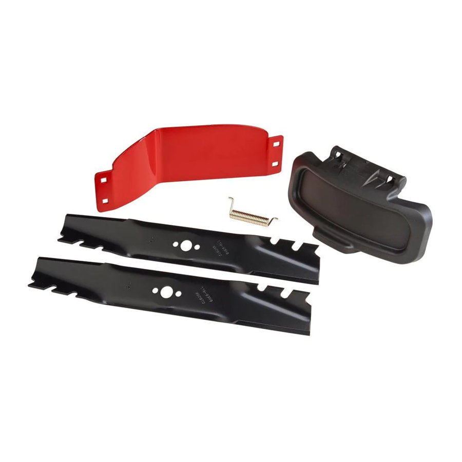
High-Lift Blade and Baffle Kit
2012 TimeMaster Lawn Mower
Model No. 127-6879
This product contains a chemical or chemicals known to the State of California to
Important: You will need a torque wrench to install the blades properly. If you do not have a torque wrench or are
uncomfortable performing this procedure, contact an Authorized Service Dealer.
Note: Determine the left and right sides of the machine from the normal operating position.
1
Preparing the Machine
No Parts Required
Procedure
1. Lock the handle in the vertical position (Figure 1); refer
to Adjusting the Handle Height in the Operator's Manual.
1. Handle locked in the vertical position
© 2013—The Toro® Company
8111 Lyndale Avenue South
Bloomington, MN 55420
Proposition 65 Warning
cause cancer, birth defects, or reproductive harm.
1
g024066
Figure 1
Register at www.Toro.com.
WARNING
CALIFORNIA
2. Disconnect the wire from the spark plug.
WARNING
The blades are sharp; contacting a blade could
result in serious personal injury.
• Disconnect the wire from the spark plug.
• Wear gloves when servicing the blade.
3. Tip the machine onto its side, with the dipstick down,
until the upper handle rests on the ground.
Form No. 3379-433 Rev A
Installation Instructions
Original Instructions (EN)
All Rights Reserved *3379-433* A
Printed in the USA
Advertisement

Related Manuals for Toro 127-6879


Summary of Contents for Toro 127-6879
- Page 1 Form No. 3379-433 Rev A High-Lift Blade and Baffle Kit 2012 TimeMaster Lawn Mower Model No. 127-6879 Installation Instructions WARNING CALIFORNIA Proposition 65 Warning This product contains a chemical or chemicals known to the State of California to cause cancer, birth defects, or reproductive harm.
- Page 2 Removing the Existing Blades Installing the Baffle No Parts Required Parts needed for this procedure: Baffle Procedure 1. Use a block of wood to hold each blade steady, and turn Procedure the blade bolt counterclockwise as shown in Figure 2. 1.
- Page 3 4. Install the other blade in the same manner as the first blade (refer to steps 1 and 2). Note: The blades should be perpendicular, forming an inverted “T” as shown in Figure 6. Installing the High-lift Blades Parts needed for this procedure: High-lift blade Procedure G016536...
- Page 4 g024068 Figure 9 g024067 1. Insert the leg of the spring here. Figure 7 6. Wedge the side-discharge-door assembly open with 1. Hex-head bolts 2. Side-discharge opening a large screwdriver so that you can install the door assembly onto the mower housing (Figure 10). 2.