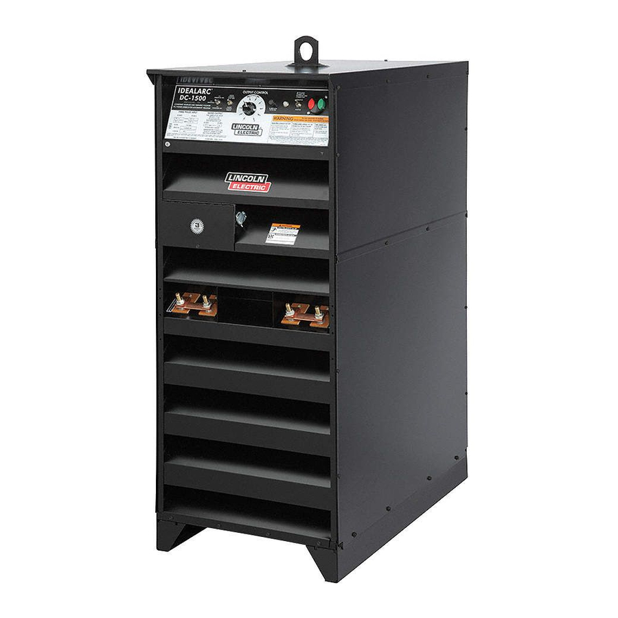
Lincoln Electric IDEALARC DC-1500 Service Manual
Constant voltage and constant current dc arc welding power source, 3 phase rectifier type
Hide thumbs
Also See for IDEALARC DC-1500:
- Operator's manual (27 pages) ,
- Technical specifications (2 pages) ,
- Specification sheet (168 pages)
Table of Contents
Advertisement
Quick Links
RETURN TO MAIN MENU
SVM202-A
July, 2010
®
IDEALARC
DC- 1500
Constant Voltage and Constant Current DC Arc Welding Power
Source, 3 Phase Rectifier Type
For use with machines having Code Numbers 8294 and above.
Safety Depends on You
Lincoln arc welding and cutting
equipment is designed and built
with safety in mind.
However,
your
overall
safety
can
be
increased by proper installation
. . . and thoughtful operation on
your part.
DO NOT INSTALL,
OPERATE OR REPAIR THIS
EQUIPMENT WITHOUT READ-
ING THIS MANUAL AND THE
SAFETY PRECAUTIONS CON-
TAINED THROUGHOUT.
And,
most importantly, think before you
act and be careful.
SERVICE MANUAL
Copyright © Lincoln Global Inc.
• World's Leader in Welding and Cutting Products •
• Sales and Service through Subsidiaries and Distributors Worldwide •
Cleveland, Ohio 44117-1199 U.S.A. TEL: 888.935.3877 FAX: 216.486.1751 WEB SITE: www.lincolnelectric.com
Advertisement
Chapters
Table of Contents
Troubleshooting

Related Manuals for Lincoln Electric IDEALARC DC-1500


Summary of Contents for Lincoln Electric IDEALARC DC-1500
- Page 1 RETURN TO MAIN MENU SVM202-A July, 2010 ® IDEALARC DC- 1500 Constant Voltage and Constant Current DC Arc Welding Power Source, 3 Phase Rectifier Type For use with machines having Code Numbers 8294 and above. Safety Depends on You Lincoln arc welding and cutting equipment is designed and built with safety in mind.
- Page 2 Miami, Florida 33135 or CSA Standard W117.2-1974. A Free copy of “Arc Welding Safety” booklet E205 is available from the Lincoln Electric Company, 22801 St. Clair Avenue, Cleveland, Ohio 44117-1199. BE SURE THAT ALL INSTALLATION, OPERATION, MAINTENANCE AND REPAIR PROCEDURES ARE PERFORMED ONLY BY QUALIFIED INDIVIDUALS.
- Page 3 SAFETY ELECTRIC SHOCK can kill. ARC RAYS can burn. 3.a. The electrode and work (or ground) circuits 4.a. Use a shield with the proper filter and cover are electrically “hot” when the welder is on. plates to protect your eyes from sparks and Do not touch these “hot”...
- Page 4 SAFETY WELDING and CUTTING CYLINDER may explode SPARKS can if damaged. cause fire or explosion. 7.a. Use only compressed cylinders 6.a. Remove fire hazards from the welding area. containing the correct shielding gas for the If this is not possible, cover them to prevent process used and properly operating the welding sparks from starting a fire.
- Page 5 SAFETY 6. Eloigner les matériaux inflammables ou les recouvrir afin de PRÉCAUTIONS DE SÛRETÉ prévenir tout risque d’incendie dû aux étincelles. Pour votre propre protection lire et observer toutes les instructions 7. Quand on ne soude pas, poser la pince à une endroit isolé de et les précautions de sûreté...
- Page 6 2004/108/EC. It was manufactured in conformity with a national standard that implements a harmonized standard: EN 60974-10 Electromagnetic Compatibility (EMC) Product Standard for Arc Welding Equipment. It is for use with other Lincoln Electric equipment. It is designed for industrial and professional use. Introduction All electrical equipment generates small amounts of electromagnetic emission.
-
Page 7: Safety
SAFETY Electromagnetic Compatibility (EMC) The size of the surrounding area to be considered will depend on the structure of the building and other activities that are taking place. The surrounding area may extend beyond the boundaries of the premises. Methods of Reducing Emissions Mains Supply Welding equipment should be connected to the mains supply according to the manufacturer’s recommen- dations. -
Page 8: Table Of Contents
- MASTER TABLE OF CONTENTS FOR ALL SECTIONS - RETURN TO MAIN MENU Page Safety ................i-vi Installation . - Page 9 TABLE OF CONTENTS - INSTALLATION SECTION Installation ................A-1 Technical Specifications .
-
Page 10: Installation
INSTALLATION TECHNICAL SPECIFICATIONS – IDEALARC® DC-1500 INPUT - THREE PHASE ONLY Standard Voltage Input Current at Rated Output 380/440/460 216/187/184 RATED OUTPUT Duty Cycle Amps Volts at Rated Amperes 100% 1500 OUTPUT Mode Current Range Maximum Open Auxiliary Power Contstant Current 200-1500 Amps Circuit Voltage 115 VAC, 8 Amps... - Page 11 INSTALLATION WARNING NOTE: The standard machines are designed to operate on 460 volt-60 Hertz, 440 volt-50 Hertz and 380 volt-50 Hertz input power systems. However, to use the machines on 380 • Do not lift this machine using lift bale if it is equipped with a volt-50 Hertz power, reconnect the transformer input leads heavy accessory such as a trail- in accordance with the connection diagram pasted to the...
- Page 12 INSTALLATION the terminal strip on the front of the DC-1500. With the #2 e. Optional Remote Control (K775) to #4 jumper connected, the output studs are en-ergized whenever the machine is on. This control is included as part of the “NL Option”. Connect it to the “NL Option”...
- Page 13 TABLE OF CONTENTS - OPERATION SECTION Operation ................B-1 Duty Cycle, Polarity &...
-
Page 14: Operation
OPERATION OPERATING INSTRUCTIONS WARNING • Do not touch electrically live parts or • Wear eye, ear and body protection. electrode with skin or wet clothing. • Insulate yourself from work and ground. ARC RAYS ELECTRIC SHOCK can burn. can kill. •... - Page 15 OPERATION 3. The VV (CC) mode is available for high current, large To Set for Machine or Remote Control puddle submerged arc procedures that cannot be done The output can be controlled either at the wire feeder or the as well with the constant voltage mode. DC-1500.
- Page 16 OPERATION If the voltmeter needle hesitates before coming up to 2. Arc striking with DC-1500 mode switch on Cv sub-arc or the desired voltage, the OCV is set too low. This will CV Innershield — There are a number of basic tech- cause the electrode to stub.
- Page 17 OPERATION General Set-Up Procedures When Using DC-1500 and b. If striking is still not satisfactory, see the NA-5 op-erat- Lincoln Automatic Head NA-5 ing manual for information on the feed motor acceler- ation. (See chart below.) c. If installed, adjust the “Start Controls” to set the weld- 1.
- Page 18 OPERATION NL Option Kit (OBSOLETE FEATURE) 4. Using the same diagram, connect the leads from the (Not Required With NA-3, NA-5, LT-7 or LT-56) option kit to the DC-1500 terminal strip. The K783 NL option kit (for field installation) is designed 5.
- Page 19 OPERATION 3. Remove the blue jumper lead connected between #1 on NOTE: The “Hot Start Control” does not affect the start- the coil of the main relay and #7 on the coil of the trans- ing method of the LAF-3, i.e., “cold” start, “hot” start, etc. fer relay.
- Page 20 NOTES IDEALARC® DC-1500...
- Page 21 TABLE OF CONTENTS - ACCESSORIES SECTION Accessories ................C-1 Connection of Machine to Wire Feeders .
-
Page 22: Accessories
ACCESSORIES Connection of DC-1500 to NA-5 N.A. Welding cables must be of proper capacity for the current and duty cycle of immediate and future applications. N.B. Extend lead 21 using #14 or larger insulated wire physically suitable for the installation. An S16586-[ ] remote voltage sensing work lead is available for this purpose. - Page 23 ACCESSORIES Connection of DC-1500 to NA-3 (All), LT-5 or LT-7 Connect the control cable ground lead to the frame terminal marked near the power source terminal strip. The power source must be properly grounded. To automatic control box. If using an older control cable: Connect lead #75 to #75 on terminal strip, connect lead #76 to #76 on terminal strip, connect lead #77 to #77 on terminal strip.
- Page 24 NOTES IDEALARC® DC-1500...
- Page 25 TABLE OF CONTENTS - MAINTENANCE SECTION Maintenance ................D-1 Safety Precautions .
-
Page 26: Maintenance
MAINTENANCE OVERLOAD PROTECTION SAFETY PRECAUTIONS The DC-1500 has built-in protective thermostats. If the WARNING rectifier or transformer reaches the maximum safe ELECTRIC SHOCK can kill. operating temprature because of frequent overload or • Do not touch electrically live parts or high room temprature because of frequent overload or electrode with skin or wet clothing. - Page 27 MAINTENANCE OVERLOAD PROTECTION WARNING The DC-1500 has built-in protective thermostats. If the recti- fier or transformer reaches the maximum safe operating tem- • Have an electrician install and service this equipment. perature because of frequent overload or high room tem-pera- ture plus overload, the contactor drops out stopping the •...
- Page 28 MAINTENANCE SCR BANK RIGHT F R O N T O F W E L D E R R E C O N N E C T P A N E L C O N T R O L T R A N S F O R M E R ( T 1 ) R I G H T S I D E M A I N C O N T A C T O R C O N T R O L P A N E L...
- Page 29 TABLE OF CONTENTS-THEORY OF OPERATION SECTION Theory of Operation ..............E-1 General Description .
-
Page 30: Theory Of Operation
THEORY OF OPERATION FIGURE E.2 - GENERAL DISCRIPTION F I R I N G B O A R D C O N T R O L B O A R D 2 / 4 R E M O T E C O N T R O L C O N T R O L B O A R D T R A N S F O R M E R 1 1 5 V A C... - Page 31 THEORY OF OPERATION FIGURE E.3 - OUTPUT RECTIFICATION, CONTROL & FEEDBACK F I R I N G B O A R D C O N T R O L B O A R D 2 / 4 R E M O T E C O N T R O L C O N T R O L B O A R D T R A N S F O R M E R 1 1 5 V A C...
- Page 32 THEORY OF OPERATION FIGURE E.4 - PROTECTION DEVICES & CIRCUITS F I R I N G B O A R D C O N T R O L B O A R D 2 / 4 R E M O T E C O N T R O L C O N T R O L B O A R D T R A N S F O R M E R 1 1 5 V A C...
- Page 33 THEORY OF OPERATION FIGURE E.5 - SCR Operation SCR OPERATION A silicon controlled rectifier (SCR) is a three terminal An SCR is fired by a short burst of current into the device used to control rather large currents to a load. gate.
- Page 34 NOTES IDEALARC® DC-1500...
- Page 35 TABLE OF CONTENTS - TROUBLESHOOTING AND REPAIR Troubleshooting and Repair ............. .F-1 How to Use Troubleshooting Guide .
-
Page 36: How To Use Troubleshooting Guide
HOW TO USE TROUBLESHOOTING GUIDE WARNING Service and Repair should only be performed by Lincoln Electric Factory Trained Personnel. Unauthorized repairs performed on this equipment may result in danger to the technician and machine operator and will invalidate your factory warranty. For your safety and to avoid Electrical Shock, please observe all safety notes and precautions detailed throughout this manual. -
Page 37: Pc Board Troubleshooting Procedures
Do not touch electrically hot parts. - If you return a PC board to The Lincoln Electric Company for credit, it must be in the static-shielding bag. This will prevent further damage and allow prop- CAUTION er failure analysis. -
Page 38: Auxiliary Transformer (T1) Voltage Test
See wiring diagram. CAUTION If for any reason you do not understand the test procedures or are unable to perform the tests/repairs safely, contact the Lincoln Electric Service Department for technical troubleshooting assistance before you proceed. Call 1-888-935-3877. IDEALARC® DC-1500... - Page 39 See wiring dia- gram. CAUTION If for any reason you do not understand the test procedures or are unable to perform the tests/repairs safely, contact the Lincoln Electric Service Department for technical troubleshooting assistance before you proceed. Call 1-888-935-3877. IDEALARC® DC-1500...
- Page 40 6. Perform SCR Output Bridge Test. CAUTION If for any reason you do not understand the test procedures or are unable to perform the tests/repairs safely, contact the Lincoln Electric Service Department for technical troubleshooting assistance before you proceed. Call 1-888-935-3877. IDEALARC® DC-1500...
- Page 41 6. Perform Main Transformer Test. CAUTION If for any reason you do not understand the test procedures or are unable to perform the tests/repairs safely, contact the Lincoln Electric Service Department for technical troubleshooting assistance before you proceed. Call 1-888-935-3877. IDEALARC® DC-1500...
- Page 42 5. Perform SCR Output Bridge Test. CAUTION If for any reason you do not understand the test procedures or are unable to perform the tests/repairs safely, contact the Lincoln Electric Service Department for technical troubleshooting assistance before you proceed. Call 1-888-935-3877. IDEALARC® DC-1500...
- Page 43 Check or replace. CAUTION If for any reason you do not understand the test procedures or are unable to perform the tests/repairs safely, contact the Lincoln Electric Service Department for technical troubleshooting assistance before you proceed. Call 1-888-935-3877. IDEALARC® DC-1500...
- Page 44 Replace if needed. CAUTION If for any reason you do not understand the test procedures or are unable to perform the tests/repairs safely, contact the Lincoln Electric Service Department for technical troubleshooting assistance before you proceed. Call 1-888-935-3877. IDEALARC® DC-1500...
- Page 45 - Replace. CAUTION If for any reason you do not understand the test procedures or are unable to perform the tests/repairs safely, contact the Lincoln Electric Service Department for technical troubleshooting assistance before you proceed. Call 1-888-935-3877. IDEALARC® DC-1500...
- Page 46 NOTES F-12 F-12 IDEALARC® DC-1500...
- Page 47 AUXILIARY TRANSFORMER (T1) VOLTAGE TEST PROCEDURE WARNING Service and repair should be performed by only Lincoln Electric factory trained personnel. Unauthorized repairs performed on this equipment may result in danger to the technician or machine operator and will invalidate your factory warranty. For your safety and to avoid electrical shock, please observe all safety notes and precautions detailed throughout this manual.
- Page 48 TROUBLESHOOTING AND REPAIR F-14 F-14 AUXILIARY TRANSFORMER (T1) VOLTAGE TEST PROCEDURE (continued) FIGURE F.1 – Auxiliary Transformer Location A U X I L I A R Y T R A N S F O R M E R ( T 1 ) R E C O N N E C T A R E A RECONNECT...
- Page 49 TROUBLESHOOTING AND REPAIR F-15 F-15 AUXILIARY TRANSFORMER (T1) VOLTAGE TEST PROCEDURE (continued) FIGURE F.2 – Auxiliary Transformer 201,202 (32) L E F T S I D E T E R M I N A L S T R I P T 5 1 F R O N T O F W E L D E R TERMINAL STRIP T51...
- Page 50 NOTES F-16 F-16 IDEALARC® DC-1500...
-
Page 51: Main Transformer (T5) Voltage Test
MAIN TRANSFORMER (T5) VOLTAGE TEST WARNING Service and repair should be performed by only Lincoln Electric factory trained personnel. Unauthorized repairs performed on this equipment may result in danger to the technician or machine operator and will invalidate your factory warranty. For your safety and to avoid electrical shock, please observe all safety notes and precautions detailed throughout this manual. - Page 52 TROUBLESHOOTING AND REPAIR F-18 F-18 MAIN TRANSFORMER (T5) VOLTAGE TEST (continued) FIGURE F.3 – Primary Output Of Contactor T1, T2, T3 (Not Shown) PRIMARY INPUT L1, L2, L3 F R O N T O F W E L D E R P R I M A R Y O U T P U T O F C O N T A C T O R T 1 , T 2 , T 3 ( U N D E R S I D E ) R I G H T S I D E...
- Page 53 TROUBLESHOOTING AND REPAIR F-19 F-19 MAIN TRANSFORMER (T5) VOLTAGE TEST (continued) FIGURE F.4. – SCR’s SCR 5 S C R 3 S C R 4 S C R 5 S C R 6 S C R 1 S C R 2 SCR 1 SCR 6 SCR 2...
- Page 54 NOTES F-20 F-20 IDEALARC® DC-1500...
- Page 55 CONTROL TRANSFORMERS (T2, T3 & T4) VOLTAGE TEST PROCEDURE WARNING Service and repair should be performed by only Lincoln Electric factory trained personnel. Unauthorized repairs performed on this equipment may result in danger to the technician or machine operator and will invalidate your factory warranty. For your safety and to avoid electrical shock, please observe all safety notes and precautions detailed throughout this manual.
- Page 56 TROUBLESHOOTING AND REPAIR F-22 F-22 CONTROL TRANSFORMERS (T2, T3 & T4) VOLTAGE TEST PROCEDURE (continued) TABLE F.1 Test Point (From) Test Point (To) Expected Reading Lead 203 Lead 204 115 VAC Lead 205 Lead 206 115 VAC Lead 207 Lead 208 115 VAC PROCEDURE 7.
- Page 57 TROUBLESHOOTING AND REPAIR F-23 F-23 CONTROL TRANSFORMERS (T2, T3 & T4) VOLTAGE TEST PROCEDURE (continued) FIGURE F.5 – TERMINAL STRIP L E F T S I D E F R O N T O F W E L D E R T E R M I N A L S T R I P T 5 1 TERMINAL...
- Page 58 NOTES F-24 F-24 IDEALARC® DC-1500...
-
Page 59: Firing Board Test
FIRING BOARD TEST PROCEDURE WARNING Service and repair should be performed by only Lincoln Electric factory trained personnel. Unauthorized repairs performed on this equipment may result in danger to the technician or machine operator and will invalidate your factory warranty. For your safety and to avoid electrical shock, please observe all safety notes and precautions detailed throughout this manual. - Page 60 TROUBLESHOOTING AND REPAIR F-26 F-26 FIRING BOARD TEST PROCEDURE (continued) FIGURE F.6 – FIRING BOARD 1 2 P I N G 1 5 8 7 - 1 9 P I N G1587-1 12 PIN 9 PIN TEST PROCEDURE FOR NORMAL WARNING FIRING BOARD OPERATION JUMPERING LEADS 2 AND 4 ELECTRICALLY...
- Page 61 TROUBLESHOOTING AND REPAIR F-27 F-27 FIRING BOARD TEST PROCEDURE (continued) FIGURE F.7 – FIRING & CONTROL BOARD LOCATION(S) L E F T S I D E F I R I N G B O A R D C O N T R O L B O A R D CONTROL BOARD FIRING BOARD LEFT SIDE...
- Page 62 TROUBLESHOOTING AND REPAIR F-28 F-28 FIRING BOARD TEST PROCEDURE (continued) FIGURE F.8 – TERMINAL STRIP JUMPER WIRE CONNECTIONS (Located under small door at front left of machine) 10. Rotate the output control potentiometer (R1). 12. If an LED continues to be lit and should not be, As the potentiometer is turned clockwise, the a circuit may be faulty on the Firing Board LEDs should glow brighter.
- Page 63 TROUBLESHOOTING AND REPAIR F-29 F-29 FIRING BOARD TEST PROCEDURE (continued) FIGURE F.9 – 6CR LOCATION L E F T S I D E 6 C R R E L A Y 6CR RELAY LEFT SIDE 15. Test the Output Pilot Relay (6CR) for opera- 16.
- Page 64 NOTES F-30 F-30 IDEALARC® DC-1500...
-
Page 65: Control Board Test
CONTROL BOARD TEST PROCEDURE WARNING Service and repair should be performed by only Lincoln Electric factory trained personnel. Unauthorized repairs performed on this equipment may result in danger to the technician or machine operator and will invalidate your factory warranty. For your safety and to avoid electrical shock, please observe all safety notes and precautions detailed throughout this manual. - Page 66 TROUBLESHOOTING AND REPAIR F-32 F-32 CONTROL BOARD TEST PROCEDURE (continued) FIGURE F.10 – JUMPER 1 2 P I N 9 P I N G 1 5 8 7 - 1 G1587-1 12 PIN 9 PIN TEST PROCEDURE FOR NORMAL CONTROL BOARD OPERATION 7.
- Page 67 TROUBLESHOOTING AND REPAIR F-33 F-33 CONTROL BOARD TEST PROCEDURE (continued) POSSIBLE PROBLEMS PERTAINING TO THE CONTROL BOARD IF LED 1 (Control Board Power) does not light, when the start switch is ON. 1. Check for 115 VAC at leads #255 to #256 of 12 pin molex plug.
- Page 68 TROUBLESHOOTING AND REPAIR F-34 F-34 CONTROL BOARD TEST PROCEDURE (continued) FIGURE F.11 – CONTROL BOARD #256 #222 # 2 1 0 # 2 2 2 # 2 5 6 # 2 5 5 G 1 5 3 0 - 1 #255 G1530-1 #210...
- Page 69 TROUBLESHOOTING AND REPAIR F-35 F-35 CONTROL BOARD TEST PROCEDURE (continued) IF LED 3 (24 VDC Internal Supply) does not IF LED 5 (Control Signal) does not light and light when the Start Button is depressed (but varies in brightness when #2 and #4 are LED 1 does light).
- Page 70 NOTES F-36 F-36 IDEALARC® DC-1500...
-
Page 71: Static Scr Test
STATIC SCR TEST PROCEDURE WARNING Service and repair should be performed by only Lincoln Electric factory trained personnel. Unauthorized repairs performed on this equipment may result in danger to the technician or machine operator and will invalidate your factory warranty. For your safety and to avoid electrical shock, please observe all safety notes and precautions detailed throughout this manual. - Page 72 TROUBLESHOOTING AND REPAIR F-38 F-38 STATIC SCR TEST PROCEDURE (continued) PROCEDURE 1. Remove main supply power to the DC-1500. 2. Remove all Molex plugs from the firing board and control board. See Figure F.12 and F.13. FIGURE F.12 – CONTROL BOARD 9 P I N M O L E X 1 2 P I N M O L E X...
- Page 73 TROUBLESHOOTING AND REPAIR F-39 F-39 STATIC SCR TEST PROCEDURE (continued) FIGURE F.14 – SCR/HEATSINK LOCATION(S) (VIEWED FROM FRONT) TOP SCR T O P S C R C A T H O D E H E A T S I N K C A T H O D E J U M P E R B A R...
- Page 74 NOTES F-40 F-40 IDEALARC® DC-1500...
- Page 75 ACTIVE SCR TEST PROCEDURE WARNING Service and repair should be performed by only Lincoln Electric factory trained personnel. Unauthorized repairs performed on this equipment may result in danger to the technician or machine operator and will invalidate your factory warranty. For your safety and to avoid electrical shock, please observe all safety notes and precautions detailed throughout this manual.
- Page 76 TROUBLESHOOTING AND REPAIR F-42 F-42 ACTIVE SCR TEST PROCEDURE (continued) PROCEDURE 1. Remove main supply power to the DC-1000. 2. Remove all Molex plugs from the Firing Board and Control Board. See Figure F.15 and F.16. FIGURE F.15 – CONTROL BOARD 9 P I N M O L E X M O L E X 1 2 P I N...
- Page 77 TROUBLESHOOTING AND REPAIR F-43 F-43 ACTIVE SCR TEST PROCEDURE (continued) FIGURE F.17 – SCR/HEATSINK LOCATION(S) TOP SCR H E A T S I N K C A T H O D E J U M P E R B A R B O T T O M S C R A N O D E H E A T S I N K...
- Page 78 TROUBLESHOOTING AND REPAIR F-44 F-44 ACTIVE SCR TEST PROCEDURE (continued) FIGURE F.18 – SCR TEST SETUP T o t e s t S C R s c o n s t r u c t t h e c i r c u i t o u t l i n e d a b o v e . R e s i s t o r v a l u e s a r e p l u s o r m i n u s t e n p e r c e n t .
- Page 79 TROUBLESHOOTING AND REPAIR F-45 F-45 NORMAL OPEN CIRCUIT VOLTAGE WAVEFORM CONSTANT CURRENT MODE - NO LOAD 0 volts 20 volts This is the typical DC open circuit volt- age waveform generated from a prop- erly operating machine. Note that each vertical division represents 20 volts and that each horizontal division rep- resents 2 milliseconds in time.
- Page 80 TROUBLESHOOTING AND REPAIR F-46 F-46 NORMAL OPEN CIRCUIT VOLTAGE WAVEFORM CONSTANT VOLTAGE INNERSHIELD - MAXIMUM OUTPUT SETTING - NO LOAD 0 volts 20 volts This is the typical DC open circuit volt- age waveform generated from a prop- erly operating machine. Note that each vertical division represents 20 volts and that each horizontal division rep- resents 2 milliseconds in time.
- Page 81 TROUBLESHOOTING AND REPAIR F-47 F-47 NORMAL OPEN CIRCUIT VOLTAGE WAVEFORM CONSTANT VOLTAGE INNERSHIELD MINIMUM OUTPUT SETTING - NO LOAD 0 volts 20 volts This is the typical DC open circuit volt- age waveform generated from a prop- erly operating machine. Note that each vertical division represents 20 volts and that each horizontal division rep- resents 2 milliseconds in time.
- Page 82 TROUBLESHOOTING AND REPAIR F-48 F-48 TYPICAL OUTPUT VOLTAGE WAVEFORM -MACHINE LOADED CONSTANT VOLTAGE INNERSHIELD MODE 0 volts 20 volts This is the typical DC open circuit volt- age waveform generated from a prop- erly operating machine. Note that each vertical division represents 10 volts and that each horizontal division rep- resents 2 milliseconds in time.
- Page 83 TROUBLESHOOTING AND REPAIR F-49 F-49 ABNORMAL OPEN CIRCUIT VOLTAGE WAVEFORM CONSTANT VOLTAGE INNERSHIELD ONE OUTPUT SCR NOT FUNCTIONING MAXIMUM OUTPUT SETTING 0 volts 20 volts This is NOT the typical DC output volt- age waveform. One output SCR is not functioning.
- Page 84 NOTES F-50 F-50 IDEALARC® DC-1500...
- Page 85 INPUT CONTACTOR (1CR) REPLACEMENT WARNING Service and repair should be performed by only Lincoln Electric factory trained personnel. Unauthorized repairs performed on this equipment may result in danger to the technician or machine operator and will invalidate your factory warranty. For your safety and to avoid electrical shock, please observe all safety notes and precautions detailed throughout this manual.
- Page 86 TROUBLESHOOTING AND REPAIR F-52 F-52 INPUT CONTACTOR (1CR) REPLACEMENT (continued) FIGURE F.19 – INPUT CONTACTOR 2 / 3 2 2 1 1 3 M O U N T I N G H O L E S F O R 1 / 4 ” S C R E W S 3 MOUNTING HOLES FOR 1/4”...
- Page 87 SCR OUTPUT BRIDGE REPLACEMENT WARNING Service and repair should be performed by only Lincoln Electric factory trained personnel. Unauthorized repairs performed on this equipment may result in danger to the technician or machine operator and will invalidate your factory warranty. For your safety and to avoid electrical shock, please observe all safety notes and precautions detailed throughout this manual.
- Page 88 TROUBLESHOOTING AND REPAIR F-54 F-54 SCR OUTPUT BRIDGE REPLACEMENT (continued) Removal Procedure: 17. Disconnect leads #211 and #247 from the bot- 1. Remove the input power from the DC-1500. tom thermostat on rectifier #6. 2. Remove the roof and all case sides. 18.
- Page 89 TROUBLESHOOTING AND REPAIR F-55 F-55 SCR OUTPUT BRIDGE REPLACEMENT (continued) FIGURE F.20 – RECTIFIER ASSEMBLY 5348-5 5348-6 5 3 4 8 - 6 5 3 4 8 - 5 L 5 3 4 8 - 4 L5348-4 IDEALARC® DC-1500...
- Page 90 TROUBLESHOOTING AND REPAIR F-56 F-56 SCR OUTPUT BRIDGE REPLACEMENT (continued) PRE-ASSEMBLY OF RECTIFIERS L5348-6 Rectifier 1. Remove the steel vertical baffle from the L5348-4 Rectifier removed rectifier and mount to a new -6 rectifi- 1. Remove the steel vertical baffle from the removed rectifier and mount to a new -4 rectifi- 2.
- Page 91 TROUBLESHOOTING AND REPAIR F-57 F-57 SCR OUTPUT BRIDGE REPLACEMENT (continued) REPLACEMENT PROCEDURE 20. Connect the bottom aluminum secondary lead to the bottom heat sink of rectifier #6. Connect 1. Place rectifier #5 into the front of the unit. the top aluminum secondary lead to the top heat sink of rectifier #6.
- Page 92 TROUBLESHOOTING AND REPAIR F-58 F-58 SCR OUTPUT BRIDGE REPLACEMENT (continued) REPLACEMENT PROCEDURE (CONT.) 39. Connect leads #74 and the ground lead to the control p.c. board. 40. Connect lead #3IA to the 5CR relay. 41. Mount the top fiber air baffle to the two rear rec- tifier brackets.
- Page 93 TROUBLESHOOTING AND REPAIR F-59 F-59 RETEST AFTER REPAIR Testing is required after the removal of any mechanical part that could affect the machine’s elec- trical characteristics, or if any electrical components are repaired or replaced. INPUT IDLE AMPS AND WATTS Input Volts/Phase/Hertz Maximum Idle Amps Maximum Idle KW...
- Page 94 TABLE OF CONTENTS - DIAGRAM SECTION Electrical Diagrams ..............G-1 Wiring Diagram - Complete Machine - (L6427) .
- Page 95 ElEcTrical DiaGramS WiriNG DiaGram - cOmplETE machiNE - (l6427) DC1500 AMP IDEALARC - WIRING DIAGRAM CENTER TERMINAL OF FUSE HOLDER N.C. 8A SLOW ELECTRODE 8A SLOW BLOW POLARITY BLOW FUSE INPUT FUSE START POWER INTERLOCKING STOP RELAY .15MFD SNUBBER .15MFD P.C.
- Page 96 ElEcTrical DiaGramS SchEmaTic - cOmplETE machiNE - (G1543) NOTE: This diagram is for reference only. It may not be accurate for all machines covered by this manual. iDEalarc® Dc-1500...
- Page 97 Lincoln Electric discourages board level troubleshooting and repair since it may compromise the quality of the design and may result in danger to the Machine Operator or Technician.
- Page 98 Lincoln Electric discourages board level troubleshooting and repair since it may compromise the quality of the design and may result in danger to the Machine Operator or Technician.
- Page 99 Lincoln Electric discourages board level troubleshooting and repair since it may compromise the quality of the design and may result in danger to the Machine Operator or Technician.
- Page 100 Lincoln Electric discourages board level troubleshooting and repair since it may compromise the quality of the design and may result in danger to the Machine Operator or Technician.