
Related Manuals for Life Fitness LIFECYCLE INRSC


Summary of Contents for Life Fitness LIFECYCLE INRSC
- Page 1 INTEGRITY RECUMBENT LIFECYCLE® EXERCISE BIKE INRSC, INRSX, INRDX, INRDSE, INRSSE, INRDST, INRST, CLUB SERIES +, INT-RB, PF-INT-RB, INT-RB-CS, INT-RB-B1, INT-RB-CS-B1 Assembly Instructions 1006867-0001 REV AE...
- Page 3 Latin America and Caribbean* Spain Hong Kong Life Fitness, LLC Life Fitness IBERIA Life Fitness Asia Pacific LTD Columbia Centre III C/Frederic Mompou 5,1º1ª 32/F, Global Trade Square 9525 Bryn Mawr Avenue 08960 Sant Just Desvern Barcelona 21 Wong Chuk Hang Road Rosemont, IL 60018 U.S.A.
- Page 4 User and Service Documents Link https://www.lftechsupport.com/web/document-library/documents Additional information is available online using the link above. أ علاه إل ر إبط باستخدإم إ لإ ن تر نت على إضافية معلومات تتوفر 点击上面的链接可在线获取更多信息。 Flere oplysninger er tilgængelige online gennem linket ovenfor. Bijkomende informatie is online beschikbaar via bovenstaande link. Vous trouverez plus d'informations en ligne à...
-
Page 5: Table Of Contents
Polar Electro Inc. © Copyright 2020, Life Fitness, LLC. All Rights Reserved. Life Fitness, Hammer Strength, Cybex, ICG and SCIFIT are registered trademarks of Life Fitness, LLC and its affiliated companies and subsidiaries. Brunswick and related trademarks used under license from Brunswick Corporation. -
Page 6: Getting Started
1. Getting Started Safety Instructions Read all instructions before use. CAUTION: Any changes or modifications to this equipment could void the product warranty. WARNING: Health-related injuries may result from incorrect or excessive use of exercise equipment. Life Fitness STRONGLY recommends seeing a physician for a complete medical exam before undertaking an exercise program, particularly if the user has a family history of high blood pressure or heart disease, is over the age of 45, smokes, has high cholesterol, is obese, or has not exercised regularly in the past year. - Page 7 • Read all warnings on each product prior to starting a workout. • If warnings are missing or damaged, please contact Customer Support Services immediately for replacement warning labels. Warning labels are shipped with every product and should be installed before product is used. Life Fitness is not responsible for missing or damaged warning labels.
-
Page 8: Consignes De
AVERTISSEMENT : Une utilisation incorrecte ou excessive de l'appareil peut entraîner des blessures. Life Fitness Recommande VIVEMENT aux utilisateurs de passer un examen médical complet avant d'entamer un programme d'entraînement, et tout particulièrement dans les cas suivants : antécédents familiaux d'hypertension (pression sanguine trop élevée) ou de pathologies cardiaques, utilisateurs de 45 ans ou plus,... - Page 9 • Si certaines étiquettes d’avertissement sont manquantes ou endommagées, contactez immédiatement le service d’assistance à la clientèle. Nous vous en fournirons de nouvelles. Les étiquettes d’avertissement sont expédiées avec les appareils et doivent être installées avant utilisation de ces derniers. Life Fitness n’est pas responsable des étiquettes manquantes ou endommagées.
-
Page 10: Where To Place And How To Stabilize The
Where to Place and How to Stabilize the Recumbent Lifecycle Bike Read the entire manual before setting up the bike. After following all Safety Instructions, move the bike to the location where it will be used. Allow a clearance of 2 ft. (0.6 m) in the directions the bike is accessed from and 3 ft. (1 m) between the front or rear of the bike or any other objects. -
Page 11: Electrical Power Requirements
The Integrity X and Integrity C consoles are powered by a rechargeable 6-volt battery. Check the battery by pressing the GO button. The console should beep and light up. The console will display the Life Fitness logo. If a prompt doesn’t appear, mount the unit and begin pedaling. -
Page 12: Product Overview
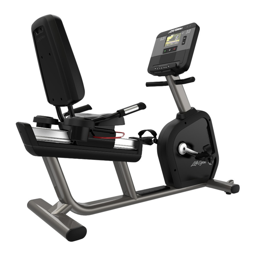
2. Product Overview INRDX, Club Series +, INT-RB-CS, INT-RB-CS-B1, INT-RB (deluxe), INT-RB-B1 (deluxe) Item Description Console Wheel Leg Leveler Resistance Up / Down Controls Cup Holders Contact Heart Rate Sensors Seat Adjustment Bar Grip INRSX, INRSC, INT-RB, PF-INT-RB, INT-RB-B1 Item Description Console Wheel... -
Page 13: Inrdse, Inrdst, Club Series +, Int-Rb-Cs, Int-Rb-Cs-B1, Int-Rb (Deluxe), Int-Rb-B1 (Deluxe)
INRDSE, INRDST, Club Series +, INT-RB-CS, INT-RB-CS-B1, INT-RB (deluxe), INT-RB-B1 (deluxe) Item Description Console Wheel Leg Leveler Resistance Up / Down Controls Cup Holders Contact Heart Rate Sensors Seat Adjustment Bar Grip Connections The following connection receptacle is located at the front of the bike. Item Description Coaxial Connection... -
Page 14: How To Adjust
How to Adjust Seat A properly adjusted seat is important in any bike-oriented exercise activity. If the seat is too close, excessive strain will be placed on the knees and quadriceps muscles. If the seat is too far, the resulting reaching action will irritate the feet, ankles, hips and knees. -
Page 15: Schedule
3. Service and Technical Data Preventive Maintenance Schedule Item Weekly Monthly Biannually Console Overlays Clean Inspect Bottle Holders / Accessory Clean Inspect Trays Console Mounting Bolts Inspect Hardware Inspect Frame / Seat Post Clean Inspect Plastic Covers Clean Inspect Lifepulse Sensors Clean / Inspect Leg Levelers Inspect / Adjust... - Page 16 Troubleshooting the Polar ® Heart Rate Chest Strap Heart rate reading is erratic or absent entirely Probable Cause Corrective Action Belt transmitter electrodes are not wet enough to pick up Wet the belt transmitter electrodes. accurate heart rate readings. Belt transmitter electrodes are not laying flat against the Ensure the belt transmitter electrodes are laying flat skin.
-
Page 17: Troubleshoot The Lifepulse
2. Locate and write down the serial number of the unit which is located on the top right of the front stabilizer. 3. Contact Life Fitness Customer Support Services at http://www.lifefitness.com. Recycle the Battery Remove and recycle the rechargeable battery before discarding this product at the end of its useful life. Disconnect the power supply (if applicable) before removing the battery. -
Page 18: Tools
4. Assembly: INRSC, INRSX, INRDX, INRDSE, INRSSE, INRDST, INRST, Club Series + Hardware and Required Tools Hardware: Item Description Qty. M8 X 20 FLANGE HEX HEAD CAP SCREW INRSC, INRSX, INRSSE, INRST INRDX, INRDSE, INRDST, Club Series + M6 X 16 PHILLIPS PAN HEAD SCREW INRSC, INRSX, INRSSE, INRST INRDX, INRDSE, INRDST, Club Series + GROMMET... -
Page 19: Attach Seat Weldment To
Attach Seat Weldment to Base 1. Route flat cable through hole. Item Description Qty. Cable 2. Attach seat weldment to base. Item Description Qty. Seat Weldment M8 X 20 Flange Head Cap Screw 37 Nm (27.3 ft. lbs.) Page 17 of 38... -
Page 20: Attach Handlebars
Attach Handlebars NOTE: Connect the cable from the handlebars to the flat cable coming up through the seat weldment. INRSX, INRSC, INRSSE, INRST INRDX, INRDSE, INRDST, CLUB SERIES + Item Description Qty. Handlebar Weldment M8 X 20 Flange Head Cap Screw Recumbent Cable Flat Cable 37 Nm (27.3 ft. -
Page 21: Attach Cup Holder Shroud (Inrsx, Inrsc, Inrsse, Inrst)
Attach Cup Holder Shroud (INRSX, INRSC, INRSSE, INRST) 1. Secure cup holder shroud with two screws. 2. Insert and twist cup holder to lock into place. Item Description Qty. Cup Holder Shroud, Right M8 X 20 Flange Head Cap Screw Cup Holder 13.5 Nm (10 ft. -
Page 22: Inrst)
Attach Seat Back and Seat Back Shroud (INRSX, INRSC, INRSSE, INRST) 1. Secure seat back to seat weldment using four screws. 2. Secure seat back shroud using four screws. Item Description Qty. Seat Back M8 X 20 Flange Head Cap Screw 13.5 Nm (10 ft. - Page 23 Attach Seat Back and Seat Back Shroud (INRDX, INRDSE, INRDST, Club Series +) 1. Secure seat back to seat weldment using four screws. 2. Secure seat back shroud using five screws. Item Description Qty. Seat Back M8 X 20 Flange Head Cap Screw 13.5 Nm (10 ft.
- Page 24 Attach Monocolumn to Base CAUTION: Remove any protective covering / tape from the monocolumn and console support weldment prior to attaching to base! Failure to remove the protective covering can cause improper grounding! NOTE: Route console cables through moncolumn. INRSX, INRSC, INRSSE, INRST INRDX, INRDSE, INRDST, CLUB SERIES + Item Description...
-
Page 25: Attach Right Monocolumn Shroud To Left
Attach Right Monocolumn Shroud to Left Monocolumn Shroud Secure the clips on the right monocolumn shroud into position on the left monocolumn shroud. NOTE: Push gasket down to shrouds. Item Description Qty. Monocolumn Shroud, Right Gasket (attached to monocolumn) Base to Console Cable Connections - Integrity X or Integrity C Item Description Console to Base Power... -
Page 26: Attach Console
Attach Console Item Description Qty. Console M5 X 14 Phillips Pan Head Screw 1.9 Nm (1.4 ft. lbs.) Attach Rear Console Shroud Assembly 1. Slide the clips on top of the rear console shroud assembly into the corresponding slots on the console mounting bracket. -
Page 27: Assembly: Int-Rb, Pf-Int-Rb, Int-Rb-Cs
5. Assembly: INT-RB, PF-INT-RB, INT-RB-CS Hardware and Required Tools Hardware: Item Description Qty. M8 X 20 FLANGE HEX HEAD CAP SCREW M6 X 16 PHILLIPS PAN HEAD SCREW INT-RB, PF-INT-RB INT-RB-CS, INT-RB (deluxe) GROMMET M4.2 X 19 PHILLIPS PAN HEAD SCREW M8 HEX LOCK NUT Required Tools: •... -
Page 28: Before You Begin
Before You Begin The monocolumn with console attached is positioned with the back of the console laying on the bike seat. The seat is set to the farthest forward position. 1. Remove velcro strap and discard. 2. Lift the moncoloumn up and turn COUNTERCLOCKWISE. NOTE: DO NOT turn the monocolumn clockwise! Cables may become twisted as a result. -
Page 29: Attach Monocolumn To
Attach Monocolumn to Base CAUTION: Remove any protective covering / tape from the monocolumn and console support weldment prior to attaching to base! Failure to remove the protective covering can cause improper grounding! INT-RB, PF-INT-RB INT-RB-CS, INT-RB (deluxe) Description Qty. Monocolumn M8 Hex Lock Nut 34 Nm ( 25.1 ft. -
Page 30: Attach Right Monocolumn Shroud To Left
Attach Right Monocolumn Shroud to Left Monocolumn Shroud Secure the clips on the right monocolumn shroud into position on the left monocolumn shroud. NOTE: Push gasket down to shrouds. Item Description Qty. Monocolumn Shroud, Right Gasket (attached to monocolumn) Attach Seat Back and Seat Back Shroud (INT-RB, PF-INT-RB) 1. -
Page 31: Attach Seat Back And Seat Back Shroud (Int- Rb-Cs, Int-Rb-Deluxe)
Attach Seat Back and Seat Back Shroud (INT-RB-CS, INT-RB-deluxe) 1. Secure seat back to seat weldment using four screws. 2. Secure seat back shroud using five screws. Item Description Qty. Seat Back M8 X 20 Flange Head Cap Screw 13.5 Nm (10 ft. lbs.) Seat Back Shroud M6 X 16 Phillips Pan Head Screw 4 Nm (35 in. -
Page 32: Attach Rear Console Shroud
Attach Rear Console Shroud Assembly 1. Slide the clips on top of the rear console shroud assembly into the corresponding slots on the console mounting bracket. 2. Use two screws and two grommets to attach rear console shroud assembly to the corresponding two holes on the console mounting bracket. -
Page 33: Assembly: Int-Rb-B1, Int-Rb-Cs-B1
6. Assembly: INT-RB-B1, INT-RB-CS-B1 Hardware and Required Tools Hardware: Item Description Qty. M8 X 20 FLANGE HEX HEAD CAP SCREW M6 X 16 PHILLIPS PAN HEAD SCREW INT-RB-B1 INT-RB-CS-B1, INT-RB-B1 (deluxe) GROMMET M5 X 14 PHILLIPS PAN HEAD SCREW M4.2 X 19 PHILLIPS PAN HEAD SCREW M8 HEX LOCK NUT Required Tools: •... -
Page 34: Before You Begin
Before You Begin The monocolumn is positioned with the back of the console support weldment laying on the bike seat. The seat is set to the farthest forward position. 1. Remove velcro strap and discard. 2. Lift the moncoloumn up and turn COUNTERCLOCKWISE. NOTE: DO NOT turn the monocolumn clockwise! Cables may become twisted as a result. -
Page 35: Attach Monocolum To
Attach Monocolum to Base CAUTION: Remove any protective covering / tape from the monocolumn and console support weldment prior to attaching to base! Failure to remove the protective covering can cause improper grounding! NOTE: Route console cables through moncolumn. INT-RB-B1 INT-RB-CS-B1, INT-RB-B1 (deluxe) Description Qty. -
Page 36: Attach Right Monocolumn Shroud To Left
Attach Right Monocolumn Shroud to Left Monocolumn Shroud Secure the clips on the right monocolumn shroud into position on the left monocolumn shroud. NOTE: Push gasket down to shrouds. Item Description Qty. Monocolumn Shroud, Right Gasket (attached to monocolumn) Attach Seat Back and Seat Back Shroud (INT-RB-B1) 1. -
Page 37: Attach Seat Back And Seat Back Shroud
Attach Seat Back and Seat Back Shroud (INT-RB-CS-B1, INT-RB-B1 - deluxe) 1. Secure seat back to seat weldment using four screws. 2. Secure seat back shroud using five screws. Item Description Qty. Seat Back M8 X 20 Flange Head Cap Screw 13.5 Nm (10 ft. -
Page 38: Base To Console Cable Connections - Discover Se3 / Se3 Hd / St
Base to Console Cable Connections - Discover SE3 / SE3 HD / ST Item Description Power Cable, 24V Base to Console Cable Coaxial Cable CAT5e HDMI (optional) IR (optional) Ground Wire Attach Console Item Description Qty. Console M5 X 14 Phillips Pan Head Screw 1.9 Nm (1.4 ft. -
Page 39: Assembly
Attach Rear Console Shroud Assembly 1. Slide the clips on top of the rear console shroud assembly into the corresponding slots on the console mounting bracket. 2. Use two screws and two grommets to attach rear console shroud assembly to the corresponding two holes on the console mounting bracket. -
Page 40: Specifications
7. Specifications Specifications Heavy / Commercial (INRSX, INRDX, INRSC, INRSSE, INRST, INRDSE, INRST, INT-RB, PF-INT-RB, INT-RB-B1) EN ISO 20957 Class SA Designed Use Home (CLUB SERIES +, INT-RB-CS, INT-RB-CS-B1) EN ISO 20957 Class HA Maximum User Weight 400 lbs. / 181 kg 5 in.