
Related Manuals for Rinnai Neo Series


Summary of Contents for Rinnai Neo Series
- Page 1 Installation guide Neo series Models: RIB2312N / RIB2312L Installer please note When completing the installation it is ideal to have the homeowner present to test the Wi-Fi connectivity and correct operation of the fire.
- Page 2 Important Appliance must be installed with a Rinnai approved flue system. This appliance shall be installed in accordance with: - Manufacturer’s installation instructions - AS/NZS 5601 Gas Installations - AS/NZS 5263 Gas appliances standards Installation, servicing and repair shall be carried out only by authorised personnel.
-
Page 3: Table Of Contents
Contents Checklist ..................4 Neo specification ................5 Inbuilt dimensions (mm) .............6 Freestanding dimensions (mm) ..........7 Gas supply and connection ............8 Electrical connection ..............9 Enclosure dimensions for inbuilt models .......10 Mantels and surrounds - inbuilt models .........11 Clearances from combustibles ..........12 TV installation .................14 Masonry installation ..............16 Inbuilt mock chimney ..............18 Freestanding installations ............20... -
Page 4: Checklist
Checklist Engine: Masonry installations Rinnai Neo heater (engine) Standard frame 2. Outer frame (standard or classic) 3. Glass outer dress guard—standard frame Mesh dress guard—classic frame (inbuilt models) Classic frame 4. Inner frame 5. Log set and granule pack (inside appliance) 6. -
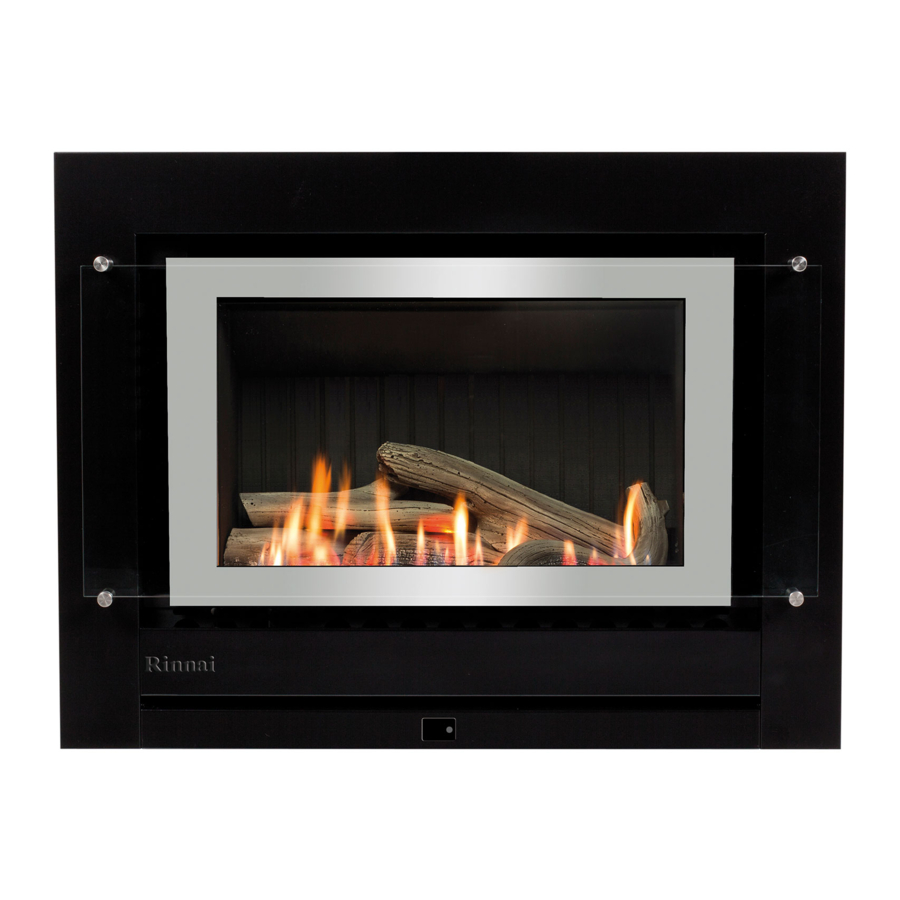
Page 5: Neo Specification
Natural draft burning log effect inbuilt gas fire with glass front and convection fan. Operated by simple infra-red remote or by the Rinnai Wi-Fi app that allows full thermostatic control, as well as other features such as timers. Different frame options available. -
Page 6: Inbuilt Dimensions (Mm)
Inbuilt dimensions (mm) includes the frame Neo Inbuilt masonry Neo Inbuilt mock chimney The above dimensions INCLUDE the zero clearance box. Neo Inbuilt Premium Classic frame 26.5 6 | Neo RIB2312 installation guide: 12148-D 04-19... -
Page 7: Freestanding Dimensions (Mm)
Freestanding dimensions (mm) includes the frame Freestanding console Freestanding plinth Neo RIB2312 installation guide: 12148-D 04-19 | 7... -
Page 8: Gas Supply And Connection
Gas supply and connection Gas pipe sizing must consider the gas input to this appliance as well as all other gas appliances in the premises. The gas meter and regulator must be specified for the total gas rate. An approved sizing chart such as the one in AS/NZS 5601.1 should be used. -
Page 9: Electrical Connection
This must be a genuine replacement part available from Rinnai. * Consult a qualified electrician if direct wiring is required as it must comply with AS/NZS 5601 and AS/NZS 3000 and other... -
Page 10: Enclosure Dimensions For Inbuilt Models
Enclosure dimensions for inbuilt models The main points governing location are flueing and warm air distribution. The enclosure dimensions provided are critical to the installation of this appliance and must be adhered to. The heater must be positioned on a flat level surface that allows free movement of the appliance. -
Page 11: Mantels And Surrounds - Inbuilt Models
Mantels and surrounds - inbuilt models only Combustible mantels and surrounds require clearance from the unit to minimise the risk of fire. Mantels and surrounds, made of combustible materials such as wood, are allowed providing they are outside the minimum clearances shown. The Neo gas fireplace is not designed to be built into bookcases. A Mantel needs to be a minimum of 400 mm away from the edge of the inner glass. -
Page 12: Clearances From Combustibles
Clearances from combustibles The clearances listed below, measured from the edge of the inner glass, are minimum clearances unless otherwise stated. While the heater is operating Neo Inbuilt clearances The appliance must not be installed where curtains or other combustible materials could come into contact with the heater. The 400 mm side clearance includes side walls. - Page 13 The below diagrams are to assist people who are determining the clearance area around the Neo without having the unit on site. Neo inbuilt 1310 Minimum above fire Clearance Glass width Clearance Neo inbuilt premium classic 1310 Minimum above fire Clearance Glass width Clearance...
-
Page 14: Tv Installation
TV installation with the TV manufacturer—some have warranty conditions that state a TV is not to be installed above a fireplace. Rinnai does not accept any responsibility for damage to a TV resulting from the use of this information. 400 mm minimum 14 | Neo RIB2312 installation guide: 12148-D 04-19... - Page 15 Installation Installation, servicing and repair shall be carried out only by authorised personnel.
-
Page 16: Masonry Installation
Masonry installation Prepare the site Ensure the enclosure meets the dimension requirements and check the gas and electrical supplies have been prepared according to information in this guide. Unpack the engine The Neo engine is supplied in one carton. Check for damage and ensure you have the correct gas type before starting. - Page 17 4. Preparing the engine Fixings R1760-2 Chimney cowl Ø 100 mm Guide rails R1760-3 Flexi flue chimney flashing plate (400 x 300 mm) R1760-6 Aluminium flexi flue 3.6 m Guide plate Flexi flue spigot adaptor 7. Inserting the engine into the fireplace. Attaching the flexiliner flue to the unit 1.
-
Page 18: Inbuilt Mock Chimney
Inbuilt mock chimney (zero clearance installation) Prepare the site Ensure the enclosure meets the dimension requirements and check the gas and electrical supplies have been prepared according to information in this guide. Ensure there are no studs, noggins, ceiling joints, wiring or other obstructions within the wall or ceiling cavity where the flue is to be located. - Page 19 Connect the gas supply Refer p. 8. Secure engine to the enclosure Fasten the engine to the enclosure using appropriate fasteners (not supplied), using the three holes across the top and at least two holes on each side, refer p. 17. Leak test Leak test all appliance connections.
-
Page 20: Freestanding Installations
Freestanding installations Prepare the site Check the installation area has been prepared according to the gas and electrical supply requirements in this guide. Ensure there are no studs, ceiling joints, wiring, or other obstructions within the ceiling cavity where the flue is to be located. Install the flue Install flue kit and/or individual flue components. - Page 21 Fitting the base assembly Minimum 119 mm Console Plinth Minimum 119mm Attach spigot adaptor and outer panels Fitting the heater to the base assembly Console Plinth Neo RIB2312 installation guide: 12148-D 04-19 | 21...
-
Page 22: Log Set And Granule Pack Installation
Log set and granule pack installation The granule pack and log set, consisting of five log pieces, comes packaged inside the appliance. The glass retainer will need to be removed before installing the granules and log set. Use extreme care when handling the log pieces, they are made from a fragile material and will damage easily. - Page 23 left hand cera granules direc fl fl fl f there are some abnormally long streaky flames, then djust granule position around ner holes until flames have improved. The granules as well as being added to create a more realistic log effect (they diffuse the gas flames through the burner ports) also assist in soot prevention and are CRITICAL to the Neo operating correctly.
-
Page 24: Inner Frame And Control Panel
Inner frame and control panel Before fitting the frame assembly ensure that it is not scratched or damaged. When placing the assembly down ensure it is placed on its lower edge or flat. WARNING If it is placed on its left or right edge the glass may slide out off the stand-off posts. -
Page 25: Commissioning
Commissioning The gas pressures must be checked against those printed on the data plate* of the appliance. The pressures are factory set and may not require adjustment. When checking the operating pressures the combustion chamber glass must be on. * Location of the data plate is on the base plate of the engine, within the air gap on the RHS of the appliance. Commissioning sheet The commissioning sheet is located in a plastic pouch, inside the unit, on top of the PCB cover. -
Page 26: Check The Wi-Fi Connection
Wi-Fi connectivity and correct operation of the fire with the homeowner. The Wi-Fi app is available on: • Google play > search Rinnai fire app • Apple store > search Rinnai fire app If unable to connect, the Wi-Fi board must be reset. -
Page 27: Outer Frame And Dress Guard
Outer frame and dress guard Locate and remove the two frame assembly securing screws pre-positioned in the mounting tabs in the heater engine body. These screws have been pre-inserted to ensure correct threading of the frame securing tabs. Attach the frame Carefully pick up the outer frame assembly. Position the top fold over the frame assembly mounting panel and gently push the lower edge of the frame assembly until it is flush at the edges. -
Page 28: Flame Pattern
Flame pattern It may take approximately two hours of operation for the logs to achieve their full flame pattern and glow. During the initial burning in period, some smoke and smell may be experienced. The appliance should run on the high setting in a well ventilated room until these dissipate. -
Page 29: Spillage Testing
If the appliance cannot be made to perform correctly please contact Rinnai. Customer handover Complete the installation and commissioning checklist in the customer operation guide, and make sure you leave the guide with the customer. Explain to the customer about the use and care of the unit, and that they understand the instructions and operation of the appliance. -
Page 30: Wiring Diagram
Wiring diagram 30 | Neo RIB2312 installation guide: 12148-D 04-19... - Page 31 Every gas fire requires a flue system that will draw effectively and clear flue products safely under all potential wind and climatic conditions. It is the responsibility of the installer to ensure the appliance is provided with an effective flue. Some guidelines to assist with flue design are detailed below. These must be read and modified as necessary depending on the installation. The Neo must be installed with an approved Rinnai flue system. General flueing guidelines Inner flue: Clearance to combustibles Clearance from the inner flue to a combustible material must be greater than 25 mm. Flue cowl clearance To ensure products of combustion are cleared, adequate clearance for the building is required.
-
Page 32: Flueing
fire. The minimum flue length before any bend or offset is 1.2 m (or one length of flue). Maximum flue length - 8 m: Rinnai recommend a maximum flue length of 8 m with a maximum of two 45 ° bends. - Page 33 Masonry flue installation with flexiliner flue Chimney flashing plate 200 mm min.* Aluminium flexi flue, minimum 3.6 m Neo flexi flue adaptor Ensure a 50 mm min. clearance from the adaptor to the back of the chimney cavity. * The end of the flue shall be at least 200 mm from the nearest part of the chimney (AS/NZS 5601.1 6.9.2 (c)) Neo RIB2312 installation guide: 12148-D 04-19 | 33...
- Page 34 Inbuilt mock chimney direct and offset flueing 500 mm min.* clearance from any part of the building, refer p. 30 Recommended clearances from combustibles 10 mm (to allow for contraction and expansion of the flue pipes) 45 ° bend, maximum of two per installation Zero clearance box fitted, must be installed flush with the cladding surface to ensure alignment of the flue.
- Page 35 Flue is built from the ground up. Refer ‘installation overview PDF for the Neo Freestanding flue kits on www.rinnai.co.nz. * The end of the flue shall be at least 500 mm from the nearest part of the chimney (AS/NZS 5601.1 6.9.2 (a))
- Page 36 Experience our innovation Rinnai.co.nz 0800 746 624 http://www.youtube.com/rinnainz Neo RIB2312 Installation Guide: 12148-D...