Advertisement
CASSETTE- TYP E AIR CONDI TION ER
Owner's Manual
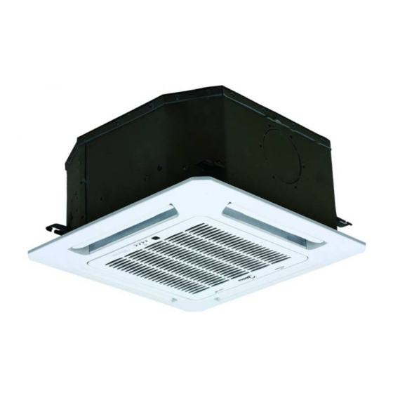
Compact Four-Way Cassette
MCA3I-09FNXD0
MCA3U-12FNXD0
MCA3U-18FNXC8
IMPORTANT NOTE:
Read this manual carefully before
installing or operating your new air
conditioning unit. Make sure to save
this manual for future reference.
Advertisement
Table of Contents

Related Manuals for Midea MCA3I-09FNXD0


Summary of Contents for Midea MCA3I-09FNXD0
- Page 1 CASSETTE- TYP E AIR CONDI TION ER Owner’s Manual Compact Four-Way Cassette MCA3I-09FNXD0 MCA3U-12FNXD0 MCA3U-18FNXC8 IMPORTANT NOTE: Read this manual carefully before installing or operating your new air conditioning unit. Make sure to save this manual for future reference.
- Page 2 Please check the applicable models, F-GAS and manufacturer information from the “Owner's Manual - Product Fiche” in the packaging of the outdoor unit. (European Union products only) Nota Importante Leggere con attenzione questo manuale prima di utilizzare il prodotto e conservarlo per la consultazione futura.Per l’identificazione dei modelli, le informazioni sul tipo di refrigerante in uso e la denominazione del produttore, fare riferimento al documento ‘’MANUALE UTENTE-SCHEDE PRODOTTO’’...
- Page 3 Table of Contents Owner’s Manual Safety Precautions ............ SAFETY FIRST Indoor Unit Parts and Major Functions ..06 Manual Operations ...........
- Page 4 Care and Maintenance ......a. Unit Maintenance ........b. How to Clean the Air Filter ....... c. Repairing Refrigerant Leaks ..... d. Preparation for Periods of Non-use ..10 Troubleshooting ......... a. Common Problems ......b. Troubleshooting Tips ......European Disposal Guidelines ..............
- Page 5 Safety Precautions Thank you for purchasing this air conditioner. This manual will provide you with information on how to operate, maintain, and troubleshoot your air conditioner. Following the instructions will ensure the proper function and extended lifespan of your unit. Please pay attention to the following signs: Failure to observe a warning may result in death.
- Page 6 This appliance can be used by children aged • CAUTION from 8 years and above and persons with DO NOT touch the air outlet while the swing • reduced physical, sensory or mental flap is in motion. Fingers might get caught capabilities or lack of experience and or the unit may break down.
- Page 7 Indoor Unit Parts And Major Functions Unit Parts Display panel Louver Air outlet Air inlet Fig. 2.1 Operating Conditions Use the system under the following temperatures for safe and e ective operation. If the air conditioner is used under di erent conditions, it may malfunction or become less e cient. COOL Mode HEAT mode DRY mode...
- Page 8 Features Default Setting Louver Angle Memory Function (Optional) When the air conditioner restarts after a power Some models are designed with a louver angle failure, it will default to the factory settings memory function. When the unit restarts after a (AUTO mode, AUTO fan, 24°C (76°F)).
- Page 9 Manual Operations This display panel on the indoor unit can be used to operate the unit in case the remote control has been misplaced or is out of batteries. Manual button Infrared receiver Operation indicator Alarm indicator Timer indicator PRE-DEF (pre-heating/defrost) indicator Fig.
- Page 10 Care And Maintenance WARNING: DO NOT REMOVE OR Safety Precautions CLEAN THE FILTER BY YOURSELF Contact an authorized service technician for • repair or maintenance. Improper repair and Removing and cleaning the filter can be maintenance may cause water leakage, dangerous.
- Page 11 Repairing Refrigerant Leaks 4. Remove the air lter. 5. Clean the air lter by vacuuming the surface or washing it in warm water with mild WARNING detergent. If the refrigerant leaks, turn o the air • A. If using a vacuum cleaner, the inlet side conditioner and any combustible heating should face the vacuum.
- Page 12 Troubleshooting CAUTIONS If one of the following conditions occurs, switch o the power supply immediately and contact your dealer for further assistance. The operation light continues to flash rapidly after the unit has been restarted. • The remote control buttons do not work. •...
- Page 13 Problem Possible Causes Dust is emitted from The unit may accumulate dust during extended periods of non-use, which either the indoor or will be emitted when the unit is turned on. This can be mitigated by covering outdoor unit the unit during long periods of inactivity. The unit may absorb odors from the environment (such as furniture, cooking, The unit emits a cigarettes, etc.) which will be emitted during operations.
- Page 14 Error Codes Indoor EEPROM (Electrically Erasable Programmable Read-Only Memory) error Indoor and outdoor unit communication malfunction Indoor fan speed malfunction Indoor room temperature sensor error Evaporator coil temperature sensor error Refrigerant leak detection system malfunction Water level alarm malfunction Dual indoor unit (twin model only) communication malfunction Other twin model malfunction Overload protection...
- Page 15 European Disposal Guidelines Users in European Countries may be required to properly dispose of this unit. This appliance contains refrigerant and other potentially hazardous materials. When disposing of this appliance, the law requires special collection and treatment. DO NOT dispose of this product as household waste or unsorted municipal waste.
- Page 17 The design and speci cations are subject to change without prior notice for product improvement.Consult with the sales agency or manufacturer for details. Page 16...
- Page 18 CASSETTE-TYPE AIR CONDITIONER Installation Manual Compact Four-Way Cassette MCA3U-12FNXD0 MCA3U-18FNXC8 IMPORTANT NOTE: Read this manual carefully before installing or operating your new air conditioning unit. Make sure to save this manual for future reference.
- Page 19 Table of Contents Installation Manual Accessories ............ Safety Precautions ........Installation Overview ....... Indoor Unit Installation Indoor Unit Installation ............a. Indoor Unit Parts ........b. Indoor Unit Installation Instructions ..09 Outdoor Unit Installation ......a. Outdoor Unit Installation Instructions ..
- Page 20 Refrigerant Piping Connection ....... A. Notes on Pipe Length and Elevation ....B. Refrigerant Piping Connection Instructions ... 17 C. Installation Of The Throttle ....... Wiring ..........a. Power Specifications ....b. Outdoor Unit Wiring ....c. Indoor Unit Wiring .......
- Page 21 Accessories The air conditioning system comes with the following accessories. Use all of the installation parts and accessories to install the air conditioner. Improper installation may result in water leakage, electrical shock and fire, or cause the equipment to fail. Name Shape Quantity...
- Page 22 Safety Precautions Read Safety Precautions Before Installation Incorrect installation due to ignoring instructions can cause serious damage or injury. The seriousness of potential damage or injuries is classified as either a WARNING or CAUTION. Failure to observe a warning may result in death. The appliance must be installed in accordance with national regulations.
- Page 23 WARNING • Any person who is involved with working on or breaking into a refrigerant circuit should hold a current valid certi cate from an industry-accredited assessment authority, which authorises their competence to handle refrigerants safely in accordance with an industry recognised assessment speci cation.
- Page 24 Installation Overview INSTALLATION ORDER Install the indoor unit Install the outdoor unit Install the drainpipe (Page 8) (Page 12) (Page 14) Evacuate the refrigeration system Connect the wires Connect the refrigerant pipes (Page 22) (Page 20) (Page 16) Install the front panel Perform a test run (Page 24) (Page 26)
- Page 25 Indoor Unit Installation Indoor Unit Parts Drain pump (within indoor unit) Drain pipe Air outlet Louver Air inlet Display panel Front grille Refrigerant pipe Fig. 4.1 Safety Precautions CAUTION WARNING • Securely install the indoor unit on a structure • Install the indoor and outdoor units, cables that can sustain its weight.
- Page 26 Indoor Unit Installation Instructions CAUTION NOTE: Panel installation should be done after DO NOT install the unit in the following piping and wiring. locations: In areas with oil drilling or fracking Step 1: Select installation location In coastal areas with high salt content in The indoor unit should be installed in a location the air that meets the following requirements:...
- Page 27 Step 2: Hang indoor unit. 1. Use the included paper template to cut a rectangular hole in the ceiling, leaving at least 1m (39”) on all sides. The hole will be 60x60cm (23.6x23.6”) big. Be sure to mark the areas where ceiling hook holes will be drilled.
- Page 28 5. Mount the indoor unit. You will need two NOTE: Ensure that the indoor unit is level. The people to lift and secure it. Insert suspension unit is equipped with a built-in drain pump and bolts into the unit’ s hanging holes. Fasten oat switch.
- Page 29 Outdoor Unit Installation The area must be free of combustible gases √ Outdoor Unit Installation Instructions and chemicals. √ The pipe length between the outdoor and Step 1: Select installation location. indoor unit may not exceed the maximum The outdoor unit should be installed in the allowable pipe length.
- Page 30 Split Type Outdoor Unit Drain Joint Installation (Refer to Fig 5.4, 5.5 and Table 5.1) Before bolting the outdoor unit in place, you must install the drain joint at the bottom of the unit. (See Fig. 5.7) 1. Fit the rubber seal on the end of the drain joint that will connect to the outdoor unit.
- Page 31 Drainpipe Installation The drainpipe is used to drain water from the NOTE ON DRAINPIPE INSTALLATION unit. Improper installation may cause unit and When using an extended drainpipe, tighten • property damage. the indoor connection with an additional protection tube to prevent it from pulling CAUTION loose.
- Page 32 3. Using a 65-mm (2.5”) core drill, drill a hole in the wall. Make sure that the hole is drilled at a slight downward angle, so that the outdoor end of the hole is lower than the indoor end by about 12mm (0.5”). This will ensure proper water drainage (See Fig.
- Page 33 Refrigerant Piping Connection Table 7.1: The Maximum Length And Drop Safety Precautions Height Based on Models. (Unit: m/ft.) WARNING Type of model Capacity Length of Maximum drop piping height (Btu/h) • All eld piping must be completed by a <15K 25/82 10/32.8 North America,...
- Page 34 Refrigerant Piping Connection Instructions CAUTION If the outdoor unit is installed higher than the CAUTION indoor unit: The branching pipe must be installed • -It is recommended that vertical suction risers horizontally. An angle of more than 10° may not be upsized. Proper oil return to the cause malfunction.
- Page 35 Step 2: Remove burrs. 6. Place flaring tool onto the form. Burrs can a ect the air-tight seal of refrigerant 7. Turn the handle of the flaring tool piping connection. They must be completely clockwise until the pipe is fully flared. Flare removed.
- Page 36 Installation Of The Throttle. (Some Models) CAUTION Ensure to wrap insulation around the piping. • Direct contact with the bare piping may result in burns or frostbite. Make sure the pipe is properly connected. • Over tightening may damage the bell mouth and under tightening may lead to leakage.
- Page 37 Wiring • No other equipment should be connected Safety Precautions to the same power circuit. • The unit’ s power information can be found WARNING on the rating sticker on the product. • Be sure to disconnect the power supply TAKE NOTE OF FUSE SPECIFICATIONS before working on the unit.
- Page 38 b. Using wire strippers, strip the rubber jacket Indoor Unit Wiring from both ends of signal cable to reveal 1. Prepare the cable for connection about 15cm (5.9”) of the wires inside. a. Using wire strippers, strip the rubber jacket c.
- Page 39 Air Evacuation 4. Turn on the vacuum pump to evacuate the Safety Precautions system. 5. Run the vacuum for at least 15 minutes, or until the Compound Meter reads -76cmHG CAUTION (-1x10⁵Pa). • Use a vacuum pump with a gauge reading 6.
- Page 40 Note On Adding Refrigerant CAUTION • Refrigerant charging must be performed after wiring, vacuuming and the leak test. DO NOT exceed the maximum allowable quantity of refrigerant or overcharge the system. • Doing so can damage or impact the unit’ s function. •...
- Page 41 Panel Installation Step 2: Install the panel CAUTION Align the indicate "△" on the decoration DO NOT place the panel facedown on the floor, panel to the indicate "△" on the unit . against a wall, or on uneven surfaces. Attach the decoration panel to the unit with the supplied screws as shown in gure below.
- Page 42 Step 3: Mount the intake grille. Step 5: Fasten the control box lid with 2 screws . Ensure that the buckles at the back of the grille be properly seated in the groove of the panel. Fig. 10.7 Step 6: Close the intake grille, and close the 2 grille hooks.
- Page 43 Test Run f. Check to see that the drainage system is Before Test Run unimpeded and draining smoothly. A test run must be performed after the entire g. Ensure there is no vibration or abnormal system has been completely installed. Confirm noise during operation.
- Page 44 European Disposal Guidelines Users in European Countries may be required to properly dispose of this unit. This appliance contains refrigerant and other potentially hazardous materials. When disposing of this appliance, the law requires special collection and treatment. DO NOT dispose of this product as household waste or unsorted municipal waste.
- Page 45 Information Servicing (Required for the units adopt R32/R290 Refrigerant only) 1. Checks to the area Prior to beginning work on systems containing flammable refrigerants, safety checks are necessary to ensure that the risk of ignition is minimised. For repair to the refrigerating system, the following precautions shall be complied with prior to conducting work on the system.
- Page 46 7. Ventilated area Ensure that the area is in the open or that it it adequately ventilated before breaking into the system or conducting any hot work. A degree of ventilation shall continue during the period that the work is carried out.
- Page 47 10. Repairs to sealed components 10.1 During repairs to sealed components, all electrical supplies shall be disconnected from the equipment being worked upon prior to any removal of sealed covers, etc. If it is absolutely necessary to have an electrical supply to equipment during servicing, then a permanently operating form of leak detection shall be located at the most critical point to warn of a potentially hazardous situation.
- Page 48 14. Leak detection methods The following leak detection methods are deemed acceptable for systems containing flammable refrigerants. Electronic leak detectors shall be used to detect flammable refrigerants, but the sensitivity may not be adequate, or may need re-calibration.(Detection equipment shall be calibrated in a refrigerant-free area.) Ensure that the detector is not a potential source of ignition and is suitable for the refrigerant.
- Page 49 When the final OFN charge is used, the system shall be vented down to atmospheric pressure to enable work to take place. This operation is absolutely vital if brazing operations on the pipe-work are to take place. Ensure that the outlet for the vacuum pump is not closed to any ignition sources and there is ventilation available.
- Page 50 f) Make sure that cylinder is situated on the scales before recovery takes place. g) Start the recovery machine and operate in accordance with manufacturer s instructions. h) Do not overfill cylinders. (No more than 80% volume liquid charge). i) Do not exceed the maximum working pressure of the cylinder, even temporarily. j) When the cylinders have been filled correctly and the process completed, make sure that the cylinders and the equipment are removed from site promptly and all isolation valves on the equipment are closed off.
- Page 51 20. Transportation, marking and storage for units 1. Transport of equipment containing ammable refrigerants Compliance with the transport regulations 2. Marking of equipment using signs Compliance with local regulations 3. Disposal of equipment using ammable refrigerants Compliance with national regulations 4.
- Page 53 The design and speci cations are subject to change without prior notice for product improvement. Consult with the sales agency or manufacturer for details. QSBPQ4I-057AEN(R32)(A3) Page 36...
- Page 54 AIR CONDITIONER REMOTE CONTROLLER ILLUSTRATION RG70C/BGEF The design and specifications are subject to change without prior notice for product improvement. Consult with the sales agency or manufacturer for details. CR176-RG70C(F) Thank you very much for purchasing our air conditioner. Please read this owner's manual carefully before using your air conditioner.
-
Page 55: Table Of Contents
Operation of buttons ON/OFF Button( This button turns the air conditioner ON CONTENTS and OFF. Temp Up Button( Press this button to increase the set Remote controller Specifications........... temperature or Timer setting hours. Operation of buttons ..............Temp Down Button( Push this button to decrease the set Indicators on LCD ................ -
Page 56: Operation Of Buttons
NOTE: Operation of buttons Swing Button Pressing the ON/OFF button, or modifying Operation of buttons Used to stop or start horizontal louver move- the mode or adjusting the set temperature to ment or set the desired up/down air flow less than 24 C will stop ECO operation. direction. -
Page 57: Indicators On Lcd
Indicators on LCD SELF CLEAN function( Mode display Under SELF CLEAN mode, the air Information are displayed when conditioner will automatically clean and the remote controller is powered dry the Evaporator and keep it as fresh for the next operation. It is not available AUTO COOL HEAT... -
Page 58: How To Use The Buttons
How to use the buttons How to use the buttons AUTO operation DRY operation(dehumidifying) SETTING TEMPERATURE 1. Press the MODE button to select DRY The operating temperature range for units is mode. 17-30 C. You can increase or decrease the 2. -
Page 59: Temp
How to use the buttons TIMER function Press the Timer button, the Timer on The TIMER OFF function allows you to indicator " " displays and flashes. By set a period of time after which the unit HEAT operation default, the last time period that you set will automatically turn off, such as when and an "h"... - Page 60 Setting both TIMER ON and TIMER OFF at the same time Example: Setting the unit to turn on after 6 hours, operate for 2 hours, then turn off (see the figure below) Keep in mind that the time periods you set for both functions refer to hours after the current time.
-
Page 61: Handling The Remote Controller
Handling the remote controller Replacing batteries The following cases signify exhausted batteries. Replace old batteries with new ones. Location of the remote controller. Receiving beep is not emitted when a signal Use the remote controller within a distance of 8 is transmitted.