Siemens SIMATIC RF185C Operating Instructions Manual
Hide thumbs
Also See for SIMATIC RF185C:
- Operating instructions manual (158 pages) ,
- Operating instructions manual (184 pages) ,
- Operating instructions manual (180 pages)
Table of Contents
Advertisement
SIMATIC RF185C, RF186C, RF188C, RF186CI, RF188CI
SIMATIC Ident
RFID systems
SIMATIC RF185C, RF186C,
RF188C, RF186CI, RF188CI
Operating Instructions
04/2020
C79000-G8976-C512-03
Introduction
Security recommendations
Description
Mounting
Connection
Configuring
Configuring with the WBM
Programming via SIMATIC
controller
Programming via XML
Programming via OPC UA
Programming via Rockwell
controller
Service and maintenance
Technical data
Dimension drawings
Appendix
Syslog messages
Service & Support
1
2
3
4
5
6
7
8
9
10
11
12
13
14
A
B
C
Advertisement
Table of Contents

Related Manuals for Siemens SIMATIC RF185C


Summary of Contents for Siemens SIMATIC RF185C
- Page 1 SIMATIC RF185C, RF186C, RF188C, RF186CI, RF188CI Introduction Security recommendations Description SIMATIC Ident Mounting RFID systems SIMATIC RF185C, RF186C, Connection RF188C, RF186CI, RF188CI Configuring Operating Instructions Configuring with the WBM Programming via SIMATIC controller Programming via XML Programming via OPC UA...
- Page 2 Note the following: WARNING Siemens products may only be used for the applications described in the catalog and in the relevant technical documentation. If products and components from other manufacturers are used, these must be recommended or approved by Siemens. Proper transport, storage, installation, assembly, commissioning, operation and maintenance are required to ensure that the products operate safely and without any problems.
-
Page 3: Table Of Contents
Configuration via XML......................59 Configuration via OPC UA ...................... 59 Configuring with Studio 5000 Logix Designer ................. 60 Configuring with the WBM ........................61 Starting WBM .......................... 61 The WBM ..........................63 SIMATIC RF185C, RF186C, RF188C, RF186CI, RF188CI Operating Instructions, 04/2020, C79000-G8976-C512-03... - Page 4 Parameterization of the diagnostics ..................153 12.2 Error messages ........................155 12.2.1 Error messages of the communications module ..............155 12.2.2 Reading out error messages using the WBM ..............163 SIMATIC RF185C, RF186C, RF188C, RF186CI, RF188CI Operating Instructions, 04/2020, C79000-G8976-C512-03...
- Page 5 Certificates & approvals ......................199 Syslog messages ..........................201 Structure of the Syslog messages ..................201 Variables in Syslog messages ....................202 List of Syslog messages ....................... 203 Service & Support ..........................207 SIMATIC RF185C, RF186C, RF188C, RF186CI, RF188CI Operating Instructions, 04/2020, C79000-G8976-C512-03...
- Page 6 Table of contents SIMATIC RF185C, RF186C, RF188C, RF186CI, RF188CI Operating Instructions, 04/2020, C79000-G8976-C512-03...
-
Page 7: Introduction
You can find information on the readers and optical readers to be connected in the manual of the respective product family (RF200, RF300, MV400, and MV500). You can find the current versions of the various manuals on the pages of the Siemens Industry Online Support (https://support.industry.siemens.com/cs/ww/en/ps/14970/man). - Page 8 Do not dispose of the products at public disposal sites. For environmentally compliant recycling and disposal of your electronic waste, please contact a company certified for the disposal of electronic waste or your Siemens representative. Adhere to the various country-specific regulations.
-
Page 9: Security Recommendations
● Keep the software up to date. Keep yourself informed regularly about safety updates for the product. You can find information about this at Link: (https://www.siemens.com/industrialsecurity). ● Activate only protocols that you actually need to use the device. ● Limit access to the device using a firewall or rules in an access control list (ACL). - Page 10 Supported formats HTTPS *.p12 OPC UA server *.pfx *.pem *.cer *.cert *.der OPC UA client *.pem OPC UA CA *.cer OPC UA issuer *.cert *.der May contain a private key. SIMATIC RF185C, RF186C, RF188C, RF186CI, RF188CI Operating Instructions, 04/2020, C79000-G8976-C512-03...
- Page 11 ● Enable only the services (protocols) that will actually be used on the device. The same applies to the installed interfaces/ports. Unused ports could be used to access the network downstream from the device. SIMATIC RF185C, RF186C, RF188C, RF186CI, RF188CI Operating Instructions, 04/2020, C79000-G8976-C512-03...
- Page 12 Closed ✓ ✓ Syslog UDP/514 Open ✓ Explanation of the table: ● Authentication Specifies whether authentication of the communication partner takes place. ● Encryption Specifies whether the transfer is encrypted. SIMATIC RF185C, RF186C, RF188C, RF186CI, RF188CI Operating Instructions, 04/2020, C79000-G8976-C512-03...
- Page 13 Siemens’ products and solutions undergo continuous development to make them more secure. Siemens strongly recommends that product updates are applied as soon as they are available and that the latest product versions are used. Use of product versions that are no longer supported, and failure to apply the latest updates may increase customers’...
- Page 14 Security recommendations SIMATIC RF185C, RF186C, RF188C, RF186CI, RF188CI Operating Instructions, 04/2020, C79000-G8976-C512-03...
-
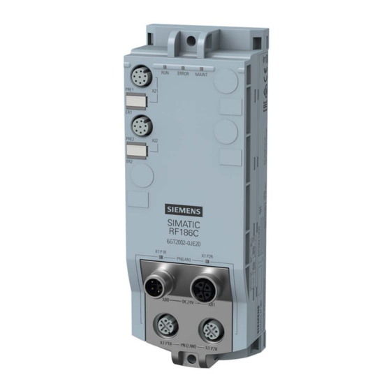
Page 15: Description
OPC UA or XML parallel to regular operation. Figure 3-1 Communication modules SIMATIC RF185C, RF186C, RF188C as well as RF186CI and RF188CI Due to the high degree of protection, mounting without a protective enclosure is possible directly near the RFID read points. - Page 16 Description 3.1 Properties of the communications modules You can find additional information on the various RFID devices and optical readers on the Internet on the "Siemens Industry Online Support (https://support.industry.siemens.com/cs/ww/en/ps/14970/man)" page. Features The following features characterize the RF18xC and RF18xCI communication modules:...
-
Page 17: I/O Functions Of The Ci Device Versions
You will find information on this in the section "Configuration via PROFINET IO (Page 52)" or "Configuring with the WBM (Page 61)". 4. Program reader commands You can find information on this in the section "Programming via SIMATIC controller (Page 111)". SIMATIC RF185C, RF186C, RF188C, RF186CI, RF188CI Operating Instructions, 04/2020, C79000-G8976-C512-03... - Page 18 Designer (Page 60)" and "Configuring with the WBM (Page 61)". 4. Configure / program the reader commands You can find information on this in the section "Programming via Rockwell controller (Page 143)". SIMATIC RF185C, RF186C, RF188C, RF186CI, RF188CI Operating Instructions, 04/2020, C79000-G8976-C512-03...
-
Page 19: Design
⑤ 2x interfaces for the power supply (M12, 4-pin, L-coded) Figure 3-2 Design of the communication module The I/O interface and I/O-LEDs are only a feature of the CI devices. SIMATIC RF185C, RF186C, RF188C, RF186CI, RF188CI Operating Instructions, 04/2020, C79000-G8976-C512-03... - Page 20 TIA Portal or another engineering system. The GSDML file is stored on the communication module and can be downloaded from it using a Web browser. You can also find the GSDML file at the website of Siemens Industry Online Support. SIMATIC RF185C, RF186C, RF188C, RF186CI, RF188CI...
-
Page 21: Mounting
Note Mounting the communication modules Only install the communication module when supply voltages are switched off. You do not have to observe any special rules when installing the communication modules. SIMATIC RF185C, RF186C, RF188C, RF186CI, RF188CI Operating Instructions, 04/2020, C79000-G8976-C512-03... -
Page 22: Mounting The Communications Module
If you need washers, use washers conforming to DIN EN ISO 7089 / DIN EN ISO 7090. Cylinder head screw with M4 hex socket accord- ing to DIN EN ISO 4762 SIMATIC RF185C, RF186C, RF188C, RF186CI, RF188CI Operating Instructions, 04/2020, C79000-G8976-C512-03... - Page 23 (≤ 1.2 Nm) onto the panel at both fastening points (front top and bottom). ① Elongated hole: 4.5 mm width × 5.0 mm height Figure 4-1 Installing RF18xC/RF18xCI communication module SIMATIC RF185C, RF186C, RF188C, RF186CI, RF188CI Operating Instructions, 04/2020, C79000-G8976-C512-03...
-
Page 24: Use At Altitudes Over 2,000 M
Note Suitability of the power supply Make sure that the power supply units you use are also suitable for altitudes > 2,000 m. SIMATIC RF185C, RF186C, RF188C, RF186CI, RF188CI Operating Instructions, 04/2020, C79000-G8976-C512-03... - Page 25 You will find the currently valid markings and approvals on the nameplate of the communication module. All other markings and approvals are currently based on an altitude up to 2,000 m. SIMATIC RF185C, RF186C, RF188C, RF186CI, RF188CI Operating Instructions, 04/2020, C79000-G8976-C512-03...
- Page 26 Mounting 4.3 Use at altitudes over 2,000 m SIMATIC RF185C, RF186C, RF188C, RF186CI, RF188CI Operating Instructions, 04/2020, C79000-G8976-C512-03...
-
Page 27: Connection
A data transfer terminal (modem, for example) is required to access the WAN (Wide Area Network) in order to ensure compliance with this safety standard. All supply and signal voltages must be safety extra low voltage (SELV/PELV according to IEC 61140). SIMATIC RF185C, RF186C, RF188C, RF186CI, RF188CI Operating Instructions, 04/2020, C79000-G8976-C512-03... -
Page 28: Network Topology
The communication network can be designed as line/series, star or ring topology. Also, note the information in the section "Supply voltage and PROFINET IO loop-through (Page 45)". Figure 5-2 Configuration graphic of a line/series topology SIMATIC RF185C, RF186C, RF188C, RF186CI, RF188CI Operating Instructions, 04/2020, C79000-G8976-C512-03... - Page 29 To make this possible you need to configure the communication modules as a client of the Media Redundancy Protocol (MRP) in STEP 7 (Basic / Professional). MRP is part of PROFINET standardization according to IEC 61158. SIMATIC RF185C, RF186C, RF188C, RF186CI, RF188CI Operating Instructions, 04/2020, C79000-G8976-C512-03...
-
Page 30: Operation Of The Cm On Grounded/Ungrounded Power Supply
Power supply units/power supply modules with safe electrical isolation are required for operation of the communication module. This protection is referred to as SELV (Safety Extra Low Voltage) / PELV (Protective Extra Low Voltage) according to IEC 61140. SIMATIC RF185C, RF186C, RF188C, RF186CI, RF188CI Operating Instructions, 04/2020, C79000-G8976-C512-03... - Page 31 Fuses for line protection (automatic circuit breaker for 16 A) ④ When setting up the communication module with an ungrounded reference potential, there is no connection between 1M, 2M, and FE Figure 5-5 Electrical design SIMATIC RF185C, RF186C, RF188C, RF186CI, RF188CI Operating Instructions, 04/2020, C79000-G8976-C512-03...
- Page 32 Isolation monitoring must be provided in the following cases: ● Design of the communication module with an ungrounded reference potential ● If hazardous plant states can be expected as a result of faults. SIMATIC RF185C, RF186C, RF188C, RF186CI, RF188CI Operating Instructions, 04/2020, C79000-G8976-C512-03...
-
Page 33: Electrical Design Of The Cm
● Communication interfaces (PROFINET) of the communication module and all other circuit components The following figure shows the potential relationships of the communication modules. Figure 5-6 Potential relationships of the communication modules SIMATIC RF185C, RF186C, RF188C, RF186CI, RF188CI Operating Instructions, 04/2020, C79000-G8976-C512-03... - Page 34 (2L+). If the load voltage (2L+) is not connected, the channel fault LED (IO-L1) is continuously lit in red. This voltage is looped through to further consumers via the I/O interface. SIMATIC RF185C, RF186C, RF188C, RF186CI, RF188CI Operating Instructions, 04/2020, C79000-G8976-C512-03...
- Page 35 5.3 Electrical design of the CM The following figure shows a configuration with another voltage supply for the communication modules. The different potential groups are highlighted in gray. Figure 5-7 Wiring of the power supply SIMATIC RF185C, RF186C, RF188C, RF186CI, RF188CI Operating Instructions, 04/2020, C79000-G8976-C512-03...
-
Page 36: Connecting Cm To Functional Ground
You need the following tool to connect to the functional ground: ● Screwdriver Accessories required You need the following accessories to connect to the functional ground: ● Fastening screw (M4) and washer SIMATIC RF185C, RF186C, RF188C, RF186CI, RF188CI Operating Instructions, 04/2020, C79000-G8976-C512-03... - Page 37 Ensure there is a low-impedance connection between the communications module and the conductive base and between the conductive base and functional ground. ① Grounded, metallic base ② Unpainted thread or nut support Figure 5-8 Mounting the CM on a conductive base SIMATIC RF185C, RF186C, RF188C, RF186CI, RF188CI Operating Instructions, 04/2020, C79000-G8976-C512-03...
-
Page 38: Mounting The Cm On A Non-Conductive Base
To connect to functional ground with a non-conductive mounting base, you can need the following accessories: ● Fastening screw (M4) and washer ● Cable lug suitable for M4 screws ● Ground conductor cable (copper braid) with a minimum cross-section of 4 mm SIMATIC RF185C, RF186C, RF188C, RF186CI, RF188CI Operating Instructions, 04/2020, C79000-G8976-C512-03... - Page 39 Grounding with non-conductive mounting base Ensure a low impedance connection between the communications module and functional ground. Figure 5-9 Mounting the CM on a non-conductive base / connection to functional ground SIMATIC RF185C, RF186C, RF188C, RF186CI, RF188CI Operating Instructions, 04/2020, C79000-G8976-C512-03...
-
Page 40: Connecting The Communications Module
You can loop the supply voltages and PROFINET IO via the M12 round sockets The pin assignments of the various interfaces are lasered on the side of each communication module at the factory. SIMATIC RF185C, RF186C, RF188C, RF186CI, RF188CI Operating Instructions, 04/2020, C79000-G8976-C512-03... - Page 41 ● for PROFINET IO connection M12 plug (4-pin, D-coded) and 4-wire Ethernet cable (Twisted Pair, shielded) You can find the associated article numbers in the section "Ordering data (Page 196)". SIMATIC RF185C, RF186C, RF188C, RF186CI, RF188CI Operating Instructions, 04/2020, C79000-G8976-C512-03...
- Page 42 Pin assignment power supply; M12 socket (4-pin, L-coded) Assignment View of M12 socket, 4-pin L1: +24 V (brown) N2: 0 V load supply (white) Relevant for RF18xCI devices N1: 0 V (blue) L2: +24 V (black) SIMATIC RF185C, RF186C, RF188C, RF186CI, RF188CI Operating Instructions, 04/2020, C79000-G8976-C512-03...
- Page 43 2L+: +24 V, for IO-Link module Class B 1N: GND, IO-Link C/Q: Data cable for IO-Link • a single digital input • a single digital output • 2N: GND, for IO-Link module Class B SIMATIC RF185C, RF186C, RF188C, RF186CI, RF188CI Operating Instructions, 04/2020, C79000-G8976-C512-03...
- Page 44 Connector for connecting digital inputs/outputs (M12, 5-pin, A-coded) ③ Connector for the power supply (M12, 4-pin, L-coded) ④ Connector for PROFINET IO connection (M12, 4-pin, D-coded) Figure 5-11 Connect the plug SIMATIC RF185C, RF186C, RF188C, RF186CI, RF188CI Operating Instructions, 04/2020, C79000-G8976-C512-03...
-
Page 45: Supply Voltage And Profinet Io Loop-Through
If you do not observe the maximum permissible supply current and the cable cross- section required, this may result in the cable isolation and contacts overheating and in the device being damaged. SIMATIC RF185C, RF186C, RF188C, RF186CI, RF188CI Operating Instructions, 04/2020, C79000-G8976-C512-03... -
Page 46: Effect Of Cable Length On The Supply Voltage
When using a 7 m power cable with ∅ 1.5 mm , the voltage drop is approx. 2.6 V with a 16 A load. SIMATIC RF185C, RF186C, RF188C, RF186CI, RF188CI Operating Instructions, 04/2020, C79000-G8976-C512-03... -
Page 47: Configuring
Procedure Proceed as follows to assign a unique device name to the communications module: 1. Open the TIA Portal with "Start > All Programs > Siemens Automation > TIA Portal Vxx". 2. Create a new project. 3. Change to the Project view. - Page 48 10.In the "PG/PC interface" drop-down list in the "Online access" area, select the network adapter via which the communications module is connected to the PG/PC. 11.Click the "Update list" button to display all reachable devices in the network. SIMATIC RF185C, RF186C, RF188C, RF186CI, RF188CI Operating Instructions, 04/2020, C79000-G8976-C512-03...
- Page 49 3. Select the option "Functions > Assign name". 4. Click the "Flash LED" button. Reaction: The LEDs on the selected communications module flash. 5. Click the "Flash LED" button again to stop the flashing. SIMATIC RF185C, RF186C, RF188C, RF186CI, RF188CI Operating Instructions, 04/2020, C79000-G8976-C512-03...
-
Page 50: Assigning The Ip Address / Device Name With Sinec Pni
Assigning the IP address / device name with SINEC PNI Requirements SINEC PNI is installed and the communication module is connected and running. You can find the SINEC PNI on the pages of the "Siemens Industry Online Support (https://support.industry.siemens.com/cs/ww/en/ps/26672/dl)". Procedure... -
Page 51: Assigning An Ip Address Via Dhcp
6. Double click on an entry in the "Request History" area. The input screen "New Entry" opens. 7. In the input box "IP Address" enter a new unique IP address. SIMATIC RF185C, RF186C, RF188C, RF186CI, RF188CI Operating Instructions, 04/2020, C79000-G8976-C512-03... -
Page 52: Configuration Via Profinet Io
The GSDML file corresponding to the communication module is stored on the communication module and can be downloaded from it via WBM. You can also find the GSDML file at the website of Siemens Industry Online Support. SIMATIC RF185C, RF186C, RF188C, RF186CI, RF188CI... - Page 53 You can set the basic parameters of the communication module, as well as the parameters of the readers connected to the communication module, using the properties window of the communication module. You can set all module-specific parameters using the following parameter groups. SIMATIC RF185C, RF186C, RF188C, RF186CI, RF188CI Operating Instructions, 04/2020, C79000-G8976-C512-03...
- Page 54 User name and password only necessary if user management is enabled The "User name" and "Password" text boxes only need to be completed if the user management of the CM in the WBM is enabled. SIMATIC RF185C, RF186C, RF188C, RF186CI, RF188CI Operating Instructions, 04/2020, C79000-G8976-C512-03...
- Page 55 57.6 kBd and the reader. 115.2 kBd When an optical reader is connected: The 921.6 kBd transmission speed selected here must match the transmission speed selected for the reader. SIMATIC RF185C, RF186C, RF188C, RF186CI, RF188CI Operating Instructions, 04/2020, C79000-G8976-C512-03...
- Page 56 IO-Link Single digital input Output: • Single digital output IO-Link: • Mode for connection of an IO-Link device with digital inputs/outputs. This parameter is only included for CI communication modules. SIMATIC RF185C, RF186C, RF188C, RF186CI, RF188CI Operating Instructions, 04/2020, C79000-G8976-C512-03...
- Page 57 The stop bits are appended to every transferred character during transmission. Interface RS422 RS422 Selection of the interface type that the connect- ed hardware (reader / optical readers) uses. RS232 SIMATIC RF185C, RF186C, RF188C, RF186CI, RF188CI Operating Instructions, 04/2020, C79000-G8976-C512-03...
- Page 58 Depending on the data transmission speed the character de- lay time is limited to a minimum value. Note that the ASCII driver also pauses between two frames during transmission. SIMATIC RF185C, RF186C, RF188C, RF186CI, RF188CI Operating Instructions, 04/2020, C79000-G8976-C512-03...
-
Page 59: Configuration Via Xml
This section is intended only for OPC UA users. Configuration of the communication module is not necessary for pure OPC UA work. You can continue directly with configuration via WBM and with programming via OPC UA. SIMATIC RF185C, RF186C, RF188C, RF186CI, RF188CI Operating Instructions, 04/2020, C79000-G8976-C512-03... -
Page 60: Configuring With Studio 5000 Logix Designer
4 bytes of the MAC address of the communication module. Note Tested programs The content described in this section was tested with the programs "Studio 5000 Logix Designer" (V21 to V28) and "RSLogix 5000" (V20). SIMATIC RF185C, RF186C, RF188C, RF186CI, RF188CI Operating Instructions, 04/2020, C79000-G8976-C512-03... -
Page 61: Configuring With The Wbm
Requirement The communication module is connected, turned on and ready for operation ("RUN" LED is lit or flashing green) and the relevant communication module has been assigned an IP address. SIMATIC RF185C, RF186C, RF188C, RF186CI, RF188CI Operating Instructions, 04/2020, C79000-G8976-C512-03... - Page 62 3. Confirm your entry by pressing the <Enter> key. Result: WBM of the communication module opens. Alternatively, you can also open the WBM from the TIA Portal. Figure 7-2 The start page of the WBM SIMATIC RF185C, RF186C, RF188C, RF186CI, RF188CI Operating Instructions, 04/2020, C79000-G8976-C512-03...
-
Page 63: The Wbm
When you have created new user profiles you need to log in with one of these user profiles when you restart the WBM. SIMATIC RF185C, RF186C, RF188C, RF186CI, RF188CI Operating Instructions, 04/2020, C79000-G8976-C512-03... - Page 64 The WBM start window is divided into the following areas: ① Toolbar/status bar and log-on ② Menu tree ③ Main window ④ Message area ⑤ Information bar Figure 7-3 Start window of the WBM SIMATIC RF185C, RF186C, RF188C, RF186CI, RF188CI Operating Instructions, 04/2020, C79000-G8976-C512-03...
- Page 65 On the right above the main window there is the status bar with the following information: ● Date/time display of the communication module ● Display of the device status ● Drop-down list for selecting the user interface language ● Logon/logoff area (with active user administration) SIMATIC RF185C, RF186C, RF188C, RF186CI, RF188CI Operating Instructions, 04/2020, C79000-G8976-C512-03...
- Page 66 If you are logged in to the WBM with the "User" role, some menu items can only be used with restrictions. You will find a list of the restrictions in the section "The "User management" menu item (Page 104)". SIMATIC RF185C, RF186C, RF188C, RF186CI, RF188CI Operating Instructions, 04/2020, C79000-G8976-C512-03...
- Page 67 While you are accessing the communication module via the WBM, if changes are being made to the communication module via the connected controller at the same time, these changes are indicated by a turquoise symbol. SIMATIC RF185C, RF186C, RF188C, RF186CI, RF188CI Operating Instructions, 04/2020, C79000-G8976-C512-03...
-
Page 68: The Menu Items Of The Wbm
Using the "Update firmware" link, you jump to the "System" menu item in which you can update firmware. The "Configuration ID" box contains a unique identifier for the configuration that was last activated on the communication module or loaded into the communication SIMATIC RF185C, RF186C, RF188C, RF186CI, RF188CI Operating Instructions, 04/2020, C79000-G8976-C512-03... - Page 69 With the "Flash" check box, you can have the LEDs of the communication module and the readers connected to it flash. This enables you to quickly and easily identify the connected devices on sight. Note that this function is not supported by all readers. SIMATIC RF185C, RF186C, RF188C, RF186CI, RF188CI Operating Instructions, 04/2020, C79000-G8976-C512-03...
-
Page 70: The "Settings - General" Menu Item
Messages relating to general events: e.g. reader startup, login to the WBM, ... ERRORS Errors and alarm messages of the communications module EVENTS Recording of all tag events COMMANDS Commands of the user application SIMATIC RF185C, RF186C, RF188C, RF186CI, RF188CI Operating Instructions, 04/2020, C79000-G8976-C512-03... -
Page 71: The "Settings - Reader Interface" Menu Item
WBM and cannot be edited. The settings of each interface are identically structured and divided into the following areas: ● Basic settings ● Reader parameters Figure 7-6 The "Settings - Reader Interface" menu item SIMATIC RF185C, RF186C, RF188C, RF186CI, RF188CI Operating Instructions, 04/2020, C79000-G8976-C512-03... - Page 72 S7 diagnostics. Hard/Soft Errors: • Critical hardware errors and errors that oc- cur during command processing are report- ed by the S7 diagnostics. The "Ext_Diag" bit is set. SIMATIC RF185C, RF186C, RF188C, RF186CI, RF188CI Operating Instructions, 04/2020, C79000-G8976-C512-03...
- Page 73 You can find more detailed information on this in the "Ident profile and Ident blocks, standard function for Ident systems (https://support.industry.siemens.com/cs/ww/en/view/109762333)" manual. SIMATIC RF185C, RF186C, RF188C, RF186CI, RF188CI Operating Instructions, 04/2020, C79000-G8976-C512-03...
- Page 74 Transponder type Selection of the transponder types used. You can find a detailed description of these parameters in the following paragraphs. SIMATIC RF185C, RF186C, RF188C, RF186CI, RF188CI Operating Instructions, 04/2020, C79000-G8976-C512-03...
- Page 75 ISO 15693 None ISO 15693 General MDS D3xx, Infineon MDS D4xx, Fujitsu - 4 KB MDS D1xx, NXP MDS D2xx, TI MDS D261, STM MDS D5xx, Fujitsu - 8 KB SIMATIC RF185C, RF186C, RF188C, RF186CI, RF188CI Operating Instructions, 04/2020, C79000-G8976-C512-03...
- Page 76 Stop bits Selection of the number of stop bits that indi- cate the end of a character. The stop bits are appended to every transferred character during transmission. SIMATIC RF185C, RF186C, RF188C, RF186CI, RF188CI Operating Instructions, 04/2020, C79000-G8976-C512-03...
- Page 77 Depending on the data transmission speed the character de- lay time is limited to a minimum value. Note that the ASCII driver also pauses between two frames during transmission. SIMATIC RF185C, RF186C, RF188C, RF186CI, RF188CI Operating Instructions, 04/2020, C79000-G8976-C512-03...
-
Page 78: The "Settings - Digital Outputs" Menu Item
The menu item is divided into the following areas: ● Basic settings ● Digital outputs Figure 7-7 The "Settings - Digital outputs" menu item SIMATIC RF185C, RF186C, RF188C, RF186CI, RF188CI Operating Instructions, 04/2020, C79000-G8976-C512-03... - Page 79 The output is turned on. ● Off The output is turned off. ● Inverted The output changes its status starting from the status that is active at the moment the event occurs. SIMATIC RF185C, RF186C, RF188C, RF186CI, RF188CI Operating Instructions, 04/2020, C79000-G8976-C512-03...
-
Page 80: The "Settings - Communication" Menu Item
You can disable STEP 7 access in the "PLC" tab. In the "OPC UA" tab, you can enable and edit the OPC UA server function of the communication module. SIMATIC RF185C, RF186C, RF188C, RF186CI, RF188CI Operating Instructions, 04/2020, C79000-G8976-C512-03... - Page 81 Click on the check box of the required network port to enable or disable it. Note Disabling the network ports Make sure that you do not disable the port via which you are currently communicating with the device. SIMATIC RF185C, RF186C, RF188C, RF186CI, RF188CI Operating Instructions, 04/2020, C79000-G8976-C512-03...
- Page 82 Write access is only possible for the SNMP variables "sysName", "sys- Location" and "sysContact" of the "system" group of MIB-2. Allow write access Check box to enable/disable write protection for SNMP variables. SIMATIC RF185C, RF186C, RF188C, RF186CI, RF188CI Operating Instructions, 04/2020, C79000-G8976-C512-03...
- Page 83 Text box for entering the address of the Syslog server to which the Sys- Syslog server log messages are transferred. Default port Text box for entering the default port of the Syslog server via which the Syslog messages are transferred. SIMATIC RF185C, RF186C, RF188C, RF186CI, RF188CI Operating Instructions, 04/2020, C79000-G8976-C512-03...
- Page 84 Select the check box "Disable EtherNet/IP" if you want to ensure that no access to the communication module takes place via EtherNet/IP. With this setting, the Ethernet interface is closed for EtherNet/IP communication with the controller. SIMATIC RF185C, RF186C, RF188C, RF186CI, RF188CI Operating Instructions, 04/2020, C79000-G8976-C512-03...
- Page 85 XML channel (1-4) Specifies which XML channels are used for communication. Below the check boxes, you can define the Ethernet ports of the respective XML channels in the text boxes. SIMATIC RF185C, RF186C, RF188C, RF186CI, RF188CI Operating Instructions, 04/2020, C79000-G8976-C512-03...
- Page 86 Information on the presence of connected readers or changes made to them Tag data events Transponder data of all registered transponders Log events Log entries Interface (1-4) Definition of which interfaces are used to transmit the selected events to the controller. SIMATIC RF185C, RF186C, RF188C, RF186CI, RF188CI Operating Instructions, 04/2020, C79000-G8976-C512-03...
- Page 87 The "OPC UA" tab is divided into the following areas: ● Basic settings ● Diagnostic settings ● Security settings ● OPC UA certificates Figure 7-11 The "Settings - Communication" menu item, "OPC UA" tab SIMATIC RF185C, RF186C, RF188C, RF186CI, RF188CI Operating Instructions, 04/2020, C79000-G8976-C512-03...
- Page 88 Read point (1-4) Definition of the read point via which the log entries are transmitted. The dis- played names depend on the interface names specified in the "Reader inter- face" menu. SIMATIC RF185C, RF186C, RF188C, RF186CI, RF188CI Operating Instructions, 04/2020, C79000-G8976-C512-03...
- Page 89 OPC UA rights. A user with OPC UA rights can be created via the WBM. The user profile preinstalled in the factory (user name: "admin", password "admin") also has OPC UA rights. SIMATIC RF185C, RF186C, RF188C, RF186CI, RF188CI Operating Instructions, 04/2020, C79000-G8976-C512-03...
- Page 90 IP address of the communication module. If any part of this information is changed, the server certificate needs to be recreated. Note: Note that the procedure can take several minutes. SIMATIC RF185C, RF186C, RF188C, RF186CI, RF188CI Operating Instructions, 04/2020, C79000-G8976-C512-03...
- Page 91 Depending on the selected certificate type, you can delete existing certificates. To do so, select the desired certificate in the list and click on the "Delete" but- ton. SIMATIC RF185C, RF186C, RF188C, RF186CI, RF188CI Operating Instructions, 04/2020, C79000-G8976-C512-03...
- Page 92 The CSR file contains all relevant information of the installed server certificate. A CA (Certificate Authority) can create a signed, module-specific server certifi- cate using this file that you can then import into this module. SIMATIC RF185C, RF186C, RF188C, RF186CI, RF188CI Operating Instructions, 04/2020, C79000-G8976-C512-03...
-
Page 93: The Menu Command "Diagnostics - Hardware Diagnostics
The menu item "Diagnostics - Hardware diagnostics" is divided into the following sections: ● Basic settings ● Monitoring status ● Status ● Error counter Figure 7-12 The menu item "Diagnostics - Hardware diagnostics" SIMATIC RF185C, RF186C, RF188C, RF186CI, RF188CI Operating Instructions, 04/2020, C79000-G8976-C512-03... - Page 94 1.5 W 1.75 W 2.0 W Max. number of tran- Maximum number of transponders to be expected that may be located in sponders the antenna field at the same time. SIMATIC RF185C, RF186C, RF188C, RF186CI, RF188CI Operating Instructions, 04/2020, C79000-G8976-C512-03...
- Page 95 Number of passive errors which occurred Active error counter Number of errors which occurred Sum of the signature and CRC errors Presence counter Time in [ms] that the transponder spent in the antenna field. SIMATIC RF185C, RF186C, RF188C, RF186CI, RF188CI Operating Instructions, 04/2020, C79000-G8976-C512-03...
- Page 96 Note Error counter readings The displayed error counter readings are counted from the last restart of the reader or the last manual reset of the error counter readings. SIMATIC RF185C, RF186C, RF188C, RF186CI, RF188CI Operating Instructions, 04/2020, C79000-G8976-C512-03...
-
Page 97: The "Diagnostics - Log" Menu Item
Type of message Which message types are signaled depends on the check boxes enabled in the menu item "Settings - General" in the "Log settings" area. Entry Text of the message SIMATIC RF185C, RF186C, RF188C, RF186CI, RF188CI Operating Instructions, 04/2020, C79000-G8976-C512-03... - Page 98 The log read by the communication module is saved as a *.csv file on the PC. ● Reset The log is deleted in the communication module. With a large number of log entries in the history, it may take several minutes before these are displayed. SIMATIC RF185C, RF186C, RF188C, RF186CI, RF188CI Operating Instructions, 04/2020, C79000-G8976-C512-03...
-
Page 99: The "Diagnostics - Service Log" Menu Item
The log records internal processes of the communication module and is required for service support by SIEMENS specialists. Only make settings on this page if you are instructed to do so by SIEMENS personnel. The log entries are also evaluated by SIEMENS personnel. - Page 100 The log is deleted in the communication module. ● Service file The log read out by the communication module is saved as an *.slf file. The service file contains additional information relevant to Siemens service personnel. SIMATIC RF185C, RF186C, RF188C, RF186CI, RF188CI Operating Instructions, 04/2020, C79000-G8976-C512-03...
-
Page 101: The "Diagnostics - Syslog Logbook" Menu Item
"Syslog messages (Page 201)". With the "Update" button you can read in the entries from the communication module again and update the list. The displayed log entries contain 128 KB of data. SIMATIC RF185C, RF186C, RF188C, RF186CI, RF188CI Operating Instructions, 04/2020, C79000-G8976-C512-03... -
Page 102: The "Edit Transponder" Menu Item
● Basic settings ● Read/write Figure 7-16 The "Edit transponder" menu item Basic settings This area enables you to select the reader or reader interface with which transponders are to be processed. SIMATIC RF185C, RF186C, RF188C, RF186CI, RF188CI Operating Instructions, 04/2020, C79000-G8976-C512-03... - Page 103 Note that, if a connection to the controller is established, the configuration of the readers is performed via the controller. To enable transponder data to be read/written via the WBM, the connected readers must have been initialized via the S7 controller beforehand. SIMATIC RF185C, RF186C, RF188C, RF186CI, RF188CI Operating Instructions, 04/2020, C79000-G8976-C512-03...
-
Page 104: The "User Management" Menu Item
CM settings, we recommend that you enable the user management and create new user profiles after the first login and delete the pre- installed profile. SIMATIC RF185C, RF186C, RF188C, RF186CI, RF188CI Operating Instructions, 04/2020, C79000-G8976-C512-03... - Page 105 This page is divided into the following areas: ● User profiles ● User properties ● Password ● Roles ● User management on / off Figure 7-18 The "User management" menu item SIMATIC RF185C, RF186C, RF188C, RF186CI, RF188CI Operating Instructions, 04/2020, C79000-G8976-C512-03...
- Page 106 Note that you as "User" can only transfer changes when the device status of the communication module is "Idle". As an "administrator", you can also transfer changes even when the device status is "Run". SIMATIC RF185C, RF186C, RF188C, RF186CI, RF188CI Operating Instructions, 04/2020, C79000-G8976-C512-03...
- Page 107 User management on / off Click the "Disable user management" button if you want to disable user management again. Note that any user has all read/write privileges (administrator rights) when user administration is disabled. SIMATIC RF185C, RF186C, RF188C, RF186CI, RF188CI Operating Instructions, 04/2020, C79000-G8976-C512-03...
-
Page 108: The Menu Item "System - System Settings
Firmware update In the "Firmware update" area, you can update the firmware of the communication module. For a detailed description of firmware updates, refer to the section Firmware update (Page 166). SIMATIC RF185C, RF186C, RF188C, RF186CI, RF188CI Operating Instructions, 04/2020, C79000-G8976-C512-03... - Page 109 Click the "Save on PC" button to transfer device description files to the connected PC. You can use these files to integrate the communication modules into the configuration software of your S7 and Rockwell controllers. SIMATIC RF185C, RF186C, RF188C, RF186CI, RF188CI Operating Instructions, 04/2020, C79000-G8976-C512-03...
-
Page 110: The Menu Command "System - Reader Firmware
RF18xCI communication modules, the WBM as well as links to the relevant documents and the Siemens Industry Online Support. Operating Instructions With the "Help" menu item, you can find the manual for the corresponding communication module, "SIMATIC RF185C, RF186C RF188C, RF186CI, RF188CI". SIMATIC RF185C, RF186C, RF188C, RF186CI, RF188CI Operating Instructions, 04/2020, C79000-G8976-C512-03... -
Page 111: Programming Via Simatic Controller
Programming via SIMATIC controller This section is intended only for S7 users. You can program and configure the SIMATIC RF185C, RF186C, RF188C as well as the RF186CI and RF188CI communication modules using Ident instructions via a SIMATIC controller. To configure Ident systems using STEP 7 Basic / Professional (TIA Portal), you need appropriate Ident instructions. - Page 112 Programming via SIMATIC controller 8.1 Digital inputs/outputs SIMATIC RF185C, RF186C, RF188C, RF186CI, RF188CI Operating Instructions, 04/2020, C79000-G8976-C512-03...
-
Page 113: Programming Via Xml
You can program the communication modules via the XML interface using XML commands. You can find detailed information on the XML diagnostic functions in the "XML programming for SIMATIC Ident (https://support.industry.siemens.com/cs/ww/en/ps/14971/man)" manual. SIMATIC RF185C, RF186C, RF188C, RF186CI, RF188CI Operating Instructions, 04/2020, C79000-G8976-C512-03... - Page 114 Programming via XML SIMATIC RF185C, RF186C, RF188C, RF186CI, RF188CI Operating Instructions, 04/2020, C79000-G8976-C512-03...
-
Page 115: Programming Via Opc Ua
OPC UA. The identification devices can be subdivided as follows: ● Text recognition devices (OCR) ● Optical readers (e.g. barcode) ● RFID reader and ● Devices for localization (RTLS). Figure 10-1 Ident devices in an OPC UA network SIMATIC RF185C, RF186C, RF188C, RF186CI, RF188CI Operating Instructions, 04/2020, C79000-G8976-C512-03... -
Page 116: Supported Methods/Functions
● An OPC UA client that wishes to use the full RFID functionality of the readers connected to a communication module needs to support the following fundamental OPC UA access mechanisms: – Data Access (DA) – Events – Methods SIMATIC RF185C, RF186C, RF188C, RF186CI, RF188CI Operating Instructions, 04/2020, C79000-G8976-C512-03... - Page 117 You can find these in the read point attributes. Table 10- 1 Assignment of read points; example based on an RF188C Reader interface BrowseName DisplayName Read_point_1 Readpoint_11 Read_point_2 Readpoint_21 Read_point_3 Readpoint_31 Read_point_4 Readpoint_41 The DisplayName can be adapted. SIMATIC RF185C, RF186C, RF188C, RF186CI, RF188CI Operating Instructions, 04/2020, C79000-G8976-C512-03...
- Page 118 Lock areas on the transponder. This function is only supported by UHF readers. SetTagPassword Set transponder-specific passwords. This function is only supported by UHF readers. ReadTag Read out transponder data. WriteTag Write transponder data. SIMATIC RF185C, RF186C, RF188C, RF186CI, RF188CI Operating Instructions, 04/2020, C79000-G8976-C512-03...
- Page 119 ("System > Device description file"). Alternatively, you can also find the node IDs through browsers by means of a generic OPC UA client through the address area of the server. SIMATIC RF185C, RF186C, RF188C, RF186CI, RF188CI Operating Instructions, 04/2020, C79000-G8976-C512-03...
- Page 120 RFID-specific settings MinRssi Lowest accepted RSSI value of the antenna This function is only supported by UHF readers. RfPower Radiated power of the antenna Diagnosis Diagnostics information Presence Presence of transponders SIMATIC RF185C, RF186C, RF188C, RF186CI, RF188CI Operating Instructions, 04/2020, C79000-G8976-C512-03...
- Page 121 You can find the specified functions under the following path in the address area of a read point: ● DeviceSet > Readpoint_x1 > IOData ● DeviceSet > Readpoint_x1 > RuntimeParameters SIMATIC RF185C, RF186C, RF188C, RF186CI, RF188CI Operating Instructions, 04/2020, C79000-G8976-C512-03...
-
Page 122: Opc Ua Variables
FALSE: Read point does not scan for transponders. • Set: TRUE: The scan process of the read point for transponders is • activated. FALSE: The scan process of the read point for transponders • is deactivated. SIMATIC RF185C, RF186C, RF188C, RF186CI, RF188CI Operating Instructions, 04/2020, C79000-G8976-C512-03... -
Page 123: Simaticidentmodelversion
The type definition of "CodeTypes" is "MultiStateDiscrete- Type". This means that the variable has an "Enum" that indicates the supported data types as "Property". Possible values 0: ByteString • 1: String • 2: ScanDataEpc • SIMATIC RF185C, RF186C, RF188C, RF186CI, RF188CI Operating Instructions, 04/2020, C79000-G8976-C512-03... -
Page 124: Rfidsettings
This is a value without a unit and with- out direct reference to the power strength. This variable is only supported by UHF readers. Possible values 0 … 255 SIMATIC RF185C, RF186C, RF188C, RF186CI, RF188CI Operating Instructions, 04/2020, C79000-G8976-C512-03... -
Page 125: Diagnosis
WBM. In this case, the Diagnostics option is automatically enabled as well. Please note that write access is no longer possible for OPC UA clients as soon as the "Parallel" option is set. SIMATIC RF185C, RF186C, RF188C, RF186CI, RF188CI Operating Instructions, 04/2020, C79000-G8976-C512-03... - Page 126 If this is not possible, use the "AutoIdLastAccessEvent" events, which are also supported by the communication modules. SIMATIC RF185C, RF186C, RF188C, RF186CI, RF188CI Operating Instructions, 04/2020, C79000-G8976-C512-03...
- Page 127 RF600. These events can also overlap in which case they can no longer be clearly assigned. In this case, the value "READPOINT" is al- ways used instead. SIMATIC RF185C, RF186C, RF188C, RF186CI, RF188CI Operating Instructions, 04/2020, C79000-G8976-C512-03...
- Page 128 • ReadTag writeTagID • • WriteTag readTagMemory • • KillTag writeTagMemory • • LockTag killTag • • SetTagPassword lockTagBank • • Read getTagStatus • • Write • READPOINT: Observed • SIMATIC RF185C, RF186C, RF188C, RF186CI, RF188CI Operating Instructions, 04/2020, C79000-G8976-C512-03...
- Page 129 The prerequisite is that the "Parallel" or "Diagnostics" option is set in the WBM. Possible values Example (RF300 reader, data type string): 0011223344556677 SIMATIC RF185C, RF186C, RF188C, RF186CI, RF188CI Operating Instructions, 04/2020, C79000-G8976-C512-03...
- Page 130 The prerequisite is that the "Parallel" or "Diagnostics" option is set in the WBM. Possible values Decimal number for the power in [dB] Increment: 0.25 dB • 5.00 ... 33.00 • SIMATIC RF185C, RF186C, RF188C, RF186CI, RF188CI Operating Instructions, 04/2020, C79000-G8976-C512-03...
- Page 131 This variable is only supported by UHF readers. The prerequisite is that the "Parallel" or "Diagnostics" option is set in the WBM. Possible values 0 ... 255 SIMATIC RF185C, RF186C, RF188C, RF186CI, RF188CI Operating Instructions, 04/2020, C79000-G8976-C512-03...
- Page 132 The prerequisite is that the "Parallel" or "Diagnostics" option is set in the WBM. Possible values Date_Time ; Type ; Entry ; Command_Type; Sequence_Number ; Readpoint ; EPCID_UID ; PC ; RSSI ; Power SIMATIC RF185C, RF186C, RF188C, RF186CI, RF188CI Operating Instructions, 04/2020, C79000-G8976-C512-03...
-
Page 133: Digitalioports
Inport05: 6th position • Inport06: 7th position • Inport07: 8th position • Depending on the value of the particular position, the corre- sponding input is at "ON" (1) or "OFF" (0). SIMATIC RF185C, RF186C, RF188C, RF186CI, RF188CI Operating Instructions, 04/2020, C79000-G8976-C512-03... - Page 134 "ON" (1) or "OFF" (0). Outputs whose state is to remain unchanged can be masked out with "x". Example: xxxxxx01 Outport01 is switched off, Outport00 is switched on, the other outputs remain unchanged. SIMATIC RF185C, RF186C, RF188C, RF186CI, RF188CI Operating Instructions, 04/2020, C79000-G8976-C512-03...
-
Page 135: Opc Ua Events
"AutoIdDiagnosisEvent" event, which in turn is derived from "BaseEvent" with its properties as defined in the OPC UA standard. Figure 10-3 Derivations of the OPC UA events based on the "BaseEvent" SIMATIC RF185C, RF186C, RF188C, RF186CI, RF188CI Operating Instructions, 04/2020, C79000-G8976-C512-03... -
Page 136: Autoidpresenceevent
0: There is no transponder in the antenna field • 1: There is at least one transponder in the antenna field • >1: Exact number of transponders (if supported by the read- • SIMATIC RF185C, RF186C, RF188C, RF186CI, RF188CI Operating Instructions, 04/2020, C79000-G8976-C512-03... -
Page 137: Rfidlastaccessevent
RF600. These events can also overlap in which case they can no longer be clearly assigned. In this case, the value "READPOINT" is al- ways used instead. SIMATIC RF185C, RF186C, RF188C, RF186CI, RF188CI Operating Instructions, 04/2020, C79000-G8976-C512-03... - Page 138 The property "LastAccessResult" is a field of "RfidLastAccessResult" structures. A field entry or a structure carries the information for a transponder that was accessed by the "Command". If multiple transponders were accessed by the command, the field has multiple entries. SIMATIC RF185C, RF186C, RF188C, RF186CI, RF188CI Operating Instructions, 04/2020, C79000-G8976-C512-03...
- Page 139 Shows the set format of the "Identifier" as String. Possible values RAW:BYTES • RAW:STRING • • Table 10- 33 Timestamp Data type UtcTime Description Time of the last transponder access Possible values Example: 2018-05-29T08:29:15.812Z SIMATIC RF185C, RF186C, RF188C, RF186CI, RF188CI Operating Instructions, 04/2020, C79000-G8976-C512-03...
- Page 140 Power with which the last command was executed on the tran- sponder. This variable is only supported by UHF readers. Possible values Decimal number for the power in [dB] Increment: 0.25 dB • 5.00 ... 33.00 • SIMATIC RF185C, RF186C, RF188C, RF186CI, RF188CI Operating Instructions, 04/2020, C79000-G8976-C512-03...
- Page 141 Table 10- 40 Strength Data type Int32 Description RSSI value with which the last command was executed on the transponder. This variable is only supported by UHF readers. Possible values 0 ... 255 SIMATIC RF185C, RF186C, RF188C, RF186CI, RF188CI Operating Instructions, 04/2020, C79000-G8976-C512-03...
-
Page 142: Autoidlastlogentryevent
BrowseName of the read point via which the event was transmitted. Possible values Example: SIMATIC_RF188C (192.168.0.254) The text of the log entry is in the "Message" Property inherited by the "BaseEvent". SIMATIC RF185C, RF186C, RF188C, RF186CI, RF188CI Operating Instructions, 04/2020, C79000-G8976-C512-03... -
Page 143: Programming Via Rockwell Controller
You can find a detailed description of the Ident profile and the add-on instructions in the "Ident profile and Ident blocks, standard function for Ident systems (https://support.industry.siemens.com/cs/ww/en/view/109762333)" function manual. SIMATIC RF185C, RF186C, RF188C, RF186CI, RF188CI Operating Instructions, 04/2020, C79000-G8976-C512-03... - Page 144 Programming via Rockwell controller SIMATIC RF185C, RF186C, RF188C, RF186CI, RF188CI Operating Instructions, 04/2020, C79000-G8976-C512-03...
-
Page 145: Service And Maintenance
● Via the LED displays of the communication modules ● Via SNMP ● Using WBM ● Via the TIA Portal (STEP 7 Basic / Professional) ● Via XML ● Via OPC UA These alternative methods are described below. SIMATIC RF185C, RF186C, RF188C, RF186CI, RF188CI Operating Instructions, 04/2020, C79000-G8976-C512-03... -
Page 146: Diagnostics Via The Led Display
Indicates that there is a link via the Ethernet interface "1". LINK P1 (X1 P1R) • Indicates that there is a link via Ethernet interface "2". LINK P2 (X1 P2R) • Figure 12-1 LED displays of the RF18xC/RF18xCI communication module SIMATIC RF185C, RF186C, RF188C, RF186CI, RF188CI Operating Instructions, 04/2020, C79000-G8976-C512-03... - Page 147 The flash test is performed for reader identification. At the same time, the LEDs of the reader and PROFINET/Ethernet LED display also flash. Communication takes place between CM and reader. The presence of a transponder is reported. SIMATIC RF185C, RF186C, RF188C, RF186CI, RF188CI Operating Instructions, 04/2020, C79000-G8976-C512-03...
- Page 148 The interface is located in the "IO-Link" configuration. An IO-Link device is connected and was recognized. There may be an error at the input/output (e.g. short-circuit). The load voltage (2L+) is not connected. SIMATIC RF185C, RF186C, RF188C, RF186CI, RF188CI Operating Instructions, 04/2020, C79000-G8976-C512-03...
-
Page 149: Diagnostics Via Snmp
You can find the MIB files corresponding to the communication modules on the pages of Siemens Industry Online Support (https://support.industry.siemens.com/cs/ww/en/view/67637278) (automation MIBs), information on the MIB files under "PROFINET user organization (https://www.profibus.com/download/profinet-specification/)". SIMATIC RF185C, RF186C, RF188C, RF186CI, RF188CI Operating Instructions, 04/2020, C79000-G8976-C512-03... -
Page 150: Diagnostics Using The Wbm
In the "Log" menu, you can find all the diagnostics messages of the communication module that have occurred. The "Service log" helps SIEMENS specialists to analyze errors. You can read out the syslog messages from the "Syslog log" and you can read out the "Status parameters"... - Page 151 – Under the "PROFINET interface" entry, you can find status information and further information about the PROFINET interface. Figure 12-2 Display of the diagnostics information of the communication module SIMATIC RF185C, RF186C, RF188C, RF186CI, RF188CI Operating Instructions, 04/2020, C79000-G8976-C512-03...
-
Page 152: Diagnostics Via Xml
Using the OPC UA variables and events, you can read out diagnostic messages and query them in a targeted manner. You can find more information on this subject in the section "Programming via OPC UA (Page 115)". SIMATIC RF185C, RF186C, RF188C, RF186CI, RF188CI Operating Instructions, 04/2020, C79000-G8976-C512-03... -
Page 153: Diagnostics Using Studio 5000 Logix Designer
Diagnostic interrupts (communication module diagnostics) If the diagnostic interrupt has been activated ("On"), the following diagnostic interrupts are reported: ● Fault in power supply ● Hardware fault ● Firmware error SIMATIC RF185C, RF186C, RF188C, RF186CI, RF188CI Operating Instructions, 04/2020, C79000-G8976-C512-03... - Page 154 The event is no longer current, a diagnostic message is output. For events that only exist momentarily, the reset is delayed by 3 seconds. Further information You can find detailed information on diagnostics on PROFINET IO in the manual "SIMATIC PROFINET system description (https://support.industry.siemens.com/cs/ww/en/view/19292127)". SIMATIC RF185C, RF186C, RF188C, RF186CI, RF188CI Operating Instructions, 04/2020, C79000-G8976-C512-03...
-
Page 155: Error Messages
The address range of the transponder has been exceeded. Possible causes: Start address of the command start has been incorrectly set. • Wrong transponder type • The area to be written to is write-protected. • SIMATIC RF185C, RF186C, RF188C, RF186CI, RF188CI Operating Instructions, 04/2020, C79000-G8976-C512-03... - Page 156 Transponder is in the limit area. • 0xE1FE8400 General transponder error 0xE1FE8500 The transponder has too little power to execute the command. Possible causes: Transponder is in the limit area. • SIMATIC RF185C, RF186C, RF188C, RF186CI, RF188CI Operating Instructions, 04/2020, C79000-G8976-C512-03...
- Page 157 The carrier signal is not activated. 0xE2FE8700 There is more than one transponder in the transmission window. 0xE2FE8800 General radio protocol error 0xE3FE0100 The file name is not allowed. 0xE3FE0200 The file does not exist. SIMATIC RF185C, RF186C, RF188C, RF186CI, RF188CI Operating Instructions, 04/2020, C79000-G8976-C512-03...
- Page 158 The specified tag field of the transponder is unknown. 0xE4FE8A00 General error 0xE4FE8B00 No or bad configuration data/parameters were transferred. Possible causes: You are accessing a read point that is not configured. • SIMATIC RF185C, RF186C, RF188C, RF186CI, RF188CI Operating Instructions, 04/2020, C79000-G8976-C512-03...
- Page 159 0xE5FE0200 Incorrect sequence number order (SN) in the Ident profile 0xE5FE0400 Invalid data block number (DBN) on the reader/communication module 0xE5FE0500 Invalid data block number (DBN) in the Ident profile SIMATIC RF185C, RF186C, RF188C, RF186CI, RF188CI Operating Instructions, 04/2020, C79000-G8976-C512-03...
- Page 160 Possible causes: The "AdvancedCmd" block was supplied with an incorrect "CMD". • The "CMD" input of the "AdvancedCmd" block was overwritten. • 0xE6FE0200 Invalid command index (CI) SIMATIC RF185C, RF186C, RF188C, RF186CI, RF188CI Operating Instructions, 04/2020, C79000-G8976-C512-03...
- Page 161 The "WRITE-CONFIG" command is incorrect. • After eliminating the error, execute an "INIT". • Check the parameter "IID_HW_CONNECT". • 0xE6FE8100 A parameter is missing. 0xE6FE8200 The parameter has an invalid format. SIMATIC RF185C, RF186C, RF188C, RF186CI, RF188CI Operating Instructions, 04/2020, C79000-G8976-C512-03...
- Page 162 Timeout during "INIT" (60 seconds) 0xE7FE0900 Command repetition is not supported. 0xE7FE0A00 Error during the transfer of the PDU (Protocol Data Unit). "--" means that the error is not displayed by the LEDs. SIMATIC RF185C, RF186C, RF188C, RF186CI, RF188CI Operating Instructions, 04/2020, C79000-G8976-C512-03...
-
Page 163: Reading Out Error Messages Using The Wbm
Program execution error on the communication module / reader – Turn the power supply of the communication mod- ule/reader off and on again – Start "INIT" after correcting the error good MISC_ERROR_ The inventory command failed. TOTAL SIMATIC RF185C, RF186C, RF188C, RF186CI, RF188CI Operating Instructions, 04/2020, C79000-G8976-C512-03... - Page 164 • "CMD". The "CMD" input of the "AdvancedCmd" block was overwrit- • ten. good DEVICE_NOT_ The specified read point is not active because no antenna was READY assigned to it. SIMATIC RF185C, RF186C, RF188C, RF186CI, RF188CI Operating Instructions, 04/2020, C79000-G8976-C512-03...
- Page 165 The selected antenna is not enabled. OpcUa_ The command is not permitted in this status or is not supported. BadInva- Possible cause: lidState "INIT" was chained. • Command repetition was started without "Presence mode". • SIMATIC RF185C, RF186C, RF188C, RF186CI, RF188CI Operating Instructions, 04/2020, C79000-G8976-C512-03...
-
Page 166: Firmware Update
In addition, the firmware of the readers connected to the communication module can be updated. The firmware of the readers is updated using the TIA Portal (STEP 7 Basic / Professional V15.1 or higher). These alternative methods are described below. SIMATIC RF185C, RF186C, RF188C, RF186CI, RF188CI Operating Instructions, 04/2020, C79000-G8976-C512-03... -
Page 167: Updating The Firmware Via Wbm
"RUN" LED is lit/flashes green. Note that the startup process takes approx. 1 minute after a firmware update. The updated firmware is active following the restart. SIMATIC RF185C, RF186C, RF188C, RF186CI, RF188CI Operating Instructions, 04/2020, C79000-G8976-C512-03... -
Page 168: Update Firmware Via Tia Portal (Step 7 Basic / Professional)
Reaction: The WBM of the communication module opens in your Web browser. Figure 12-3 Firmware update of the communication module 7. Continue the firmware update as described in the section "Updating the firmware via WBM (Page 167)". SIMATIC RF185C, RF186C, RF188C, RF186CI, RF188CI Operating Instructions, 04/2020, C79000-G8976-C512-03... -
Page 169: Updating Firmware Of The Readers Using The Tia Portal (Step 7 Basic / Professional)
4. Select the affected communication module and switch to the device view. 5. Establish an online connection. 6. Right-click on the desired communication module to which the respective reader is connected and click on "Online & Diagnostics" in the shortcut menu. SIMATIC RF185C, RF186C, RF188C, RF186CI, RF188CI Operating Instructions, 04/2020, C79000-G8976-C512-03... - Page 170 – Note: If the check box is not selected, the new firmware is only activated on the next startup of the communication module. 10.Click the "Start upgrade" button. Result: The firmware is updated. The update process is displayed. SIMATIC RF185C, RF186C, RF188C, RF186CI, RF188CI Operating Instructions, 04/2020, C79000-G8976-C512-03...
-
Page 171: Factory Defaults
The communication module is ready for operation when the "RUN" LED is lit/flashes green. After restarting the communication module, you may have to assign a new IP address or a new device name to the communication module. SIMATIC RF185C, RF186C, RF188C, RF186CI, RF188CI Operating Instructions, 04/2020, C79000-G8976-C512-03... -
Page 172: Reset The Factory Setting With Sinec Pni
"RUN" LED. After restoring, the reader is restarted. The reader is ready for operation when the "RUN" LED is lit/flashes green. After restarting the reader, you may need to assign a new IP address or a new device name to the reader. SIMATIC RF185C, RF186C, RF188C, RF186CI, RF188CI Operating Instructions, 04/2020, C79000-G8976-C512-03... -
Page 173: Restoring The Factory Settings Manually
WBM and browser is lost. After restarting the communication module, you may have to assign a new IP address or a new device name to the communication module. SIMATIC RF185C, RF186C, RF188C, RF186CI, RF188CI Operating Instructions, 04/2020, C79000-G8976-C512-03... -
Page 174: Module Replacement
● With the help of the TIA Portal (STEP 7 Basic / Professional from V15.1) in a STEP 7 project ● Using the WBM on your PC These alternative methods are described below. SIMATIC RF185C, RF186C, RF188C, RF186CI, RF188CI Operating Instructions, 04/2020, C79000-G8976-C512-03... -
Page 175: Backup Configuration Data
You can find additional information on programming the blocks and the structure of the configuration data in the section "Config_Upload/Download" of the manual "Ident Profile and Ident Blocks, Standard function for Ident systems". SIMATIC RF185C, RF186C, RF188C, RF186CI, RF188CI Operating Instructions, 04/2020, C79000-G8976-C512-03... - Page 176 These buttons enable you to save configurations, reload them and transfer them to other communication modules. You will find further information on saving and loading the configuration on or from the PC in the section "The WBM (Page 63)". SIMATIC RF185C, RF186C, RF188C, RF186CI, RF188CI Operating Instructions, 04/2020, C79000-G8976-C512-03...
-
Page 177: Replacing A Module
Only wire the SIMATIC controller and the communications modules to be switched on when the voltage is switched off. Make sure that the power supply is turned off when installing/uninstalling the devices. SIMATIC RF185C, RF186C, RF188C, RF186CI, RF188CI Operating Instructions, 04/2020, C79000-G8976-C512-03... - Page 178 ● The new communications module is in the factory state, i.e. no device name and no IP address have been assigned. If the communications module is not in the factory state, the factory settings of the module must be restored. SIMATIC RF185C, RF186C, RF188C, RF186CI, RF188CI Operating Instructions, 04/2020, C79000-G8976-C512-03...
-
Page 179: Technical Data
< 100 m at 921.6 Kbaud • dependent on reader (preassembled cables 2 ... 50 m; for other stand- ard cables and custom assembled cables, refer to the section "Connecting cables to the reader") SIMATIC RF185C, RF186C, RF188C, RF186CI, RF188CI Operating Instructions, 04/2020, C79000-G8976-C512-03... - Page 180 All supply and signal voltages must be safety extra low voltage (SELV/PELV according to IEC 61140) 24 V DC supply: Safety (electrical) isolation of low voltage (SELV/PELV acc. to IEC 61140) SIMATIC RF185C, RF186C, RF188C, RF186CI, RF188CI Operating Instructions, 04/2020, C79000-G8976-C512-03...
-
Page 181: Technical Specifications For Rf186Ci, Rf188Ci
"Connecting cables to the reader") I/O interface Connector M12 interface, 5-pin, A-coded Max. cable length 20 m Connectable I/O devices Input • Output • IO-Link module • (Input/Output module; Class A, B) SIMATIC RF185C, RF186C, RF188C, RF186CI, RF188CI Operating Instructions, 04/2020, C79000-G8976-C512-03... - Page 182 All supply and signal voltages must be safety extra low voltage (SELV/PELV according to IEC 61140) 24 V DC supply: Safety (electrical) isolation of low voltage (SELV/PELV acc. to IEC 61140) SIMATIC RF185C, RF186C, RF188C, RF186CI, RF188CI Operating Instructions, 04/2020, C79000-G8976-C512-03...
-
Page 183: Dimension Drawings
All dimensions in [mm]. ① Elongated hole: 4.5 mm width × 5.0 mm height Figure 14-1 Dimension drawing of an RF18xC communication module The figure shows an RF188C communication module. SIMATIC RF185C, RF186C, RF188C, RF186CI, RF188CI Operating Instructions, 04/2020, C79000-G8976-C512-03... - Page 184 Dimension drawings ① Elongated hole: 4.5 mm width × 5.0 mm height Figure 14-2 Dimension drawing of an RF18xCI communication module The figure shows an RF188CI communication module. SIMATIC RF185C, RF186C, RF188C, RF186CI, RF188CI Operating Instructions, 04/2020, C79000-G8976-C512-03...
-
Page 185: Appendix
The SIMATIC Ident Configuration Guide is an ID-specific guide that supports you in selecting the products relevant for your Ident system by clearly displaying all compatible devices and connecting cables. SIMATIC RF185C, RF186C, RF188C, RF186CI, RF188CI Operating Instructions, 04/2020, C79000-G8976-C512-03... -
Page 186: Connecting Cables
A reader connector with screw terminals is available for self- assembly (see the relevant system manual). Cables and reader connectors can be ordered using the TIA Selection Tool or the SIMATIC Ident Configuration Guide. SIMATIC RF185C, RF186C, RF188C, RF186CI, RF188CI Operating Instructions, 04/2020, C79000-G8976-C512-03... - Page 187 Assignment Core color RS422 RS232 +24 V +24 V Note data sheet provided -RxD by cable manufacturer +RxD +TxD +5 V -TxD Functional Functional ground / ground / shielding shielding SIMATIC RF185C, RF186C, RF188C, RF186CI, RF188CI Operating Instructions, 04/2020, C79000-G8976-C512-03...
-
Page 188: Operation Of Optical Handheld Readers, Access Control Readers Or Serial Devices
1.6 m. Due to its coiling, it can be extended to a length of 4 m during operation. A preassembled cable is also available for connection of the SIMATIC RF1040R/RF1070R readers. SIMATIC RF185C, RF186C, RF188C, RF186CI, RF188CI Operating Instructions, 04/2020, C79000-G8976-C512-03... -
Page 189: Hardware Configuration
2. Select the user mode "FB 45" or "Ident profile". 3. Set all other parameters (see below) as required and download the configuration to the controller. SIMATIC RF185C, RF186C, RF188C, RF186CI, RF188CI Operating Instructions, 04/2020, C79000-G8976-C512-03... - Page 190 No further settings need to be made for the RF1040R/RF1070R reader. In its delivery state, the reader is set so that it can be operated both via USB as well as the R232 interface. SIMATIC RF185C, RF186C, RF188C, RF186CI, RF188CI Operating Instructions, 04/2020, C79000-G8976-C512-03...
-
Page 191: Functions And Commands
No length information in the result; max. net data 229 bytes Write Sending data The address must be specified as “0xFFFF”. Max. net data 194 bytes (without length information); no error message if the length is ex- ceeded SIMATIC RF185C, RF186C, RF188C, RF186CI, RF188CI Operating Instructions, 04/2020, C79000-G8976-C512-03... - Page 192 When doing this, note the buffer size and the buffer overflow. If the receive buffer of the CM is full, existing data is overwritten by newly received data. SIMATIC RF185C, RF186C, RF188C, RF186CI, RF188CI Operating Instructions, 04/2020, C79000-G8976-C512-03...
-
Page 193: Block-Specific Error Messages
Scan operation: The newest data is lost. • With the "Write" command the oldest acknowledgements are lost without an error message being generated. 0xE6FE05 "Reset_Reader" necessary 0xE5FE04 Invalid data block number (DBN) on the reader/communication module SIMATIC RF185C, RF186C, RF188C, RF186CI, RF188CI Operating Instructions, 04/2020, C79000-G8976-C512-03... -
Page 194: Compatibility With Simatic Rf180C
Depending on the channel in which the module is used, you must adapt the module name accordingly ("_2" for channel 2). ● SIMATIC RF18xC In the "Ident device" parameter, select the module of the corresponding channel (e.g. "Reader_1" for "Channel1"). SIMATIC RF185C, RF186C, RF188C, RF186CI, RF188CI Operating Instructions, 04/2020, C79000-G8976-C512-03... - Page 195 – Parameter assignment with the "HW_Connect" variable: Adapt the "CM_CHANNEL" and "LADDR" parameters in the "HW_CONNECT" variable. When you establish the connection via an S7-1200/-1500 controller, you must also adapt the "HW_ID" parameter. SIMATIC RF185C, RF186C, RF188C, RF186CI, RF188CI Operating Instructions, 04/2020, C79000-G8976-C512-03...
-
Page 196: Ordering Data
M12-180 / M12-90 10 m 6GT2891-4JN10 CM adapter cable 0.5 m 6GF3500-8BA11 for MV500 6GF3500-8BA12 CM connecting cable 1.6 m 6GT2191-0BH50 for MV320 CM connecting cable 2.0 m 6GT2891-4UH20 for RF1000 SIMATIC RF185C, RF186C, RF188C, RF186CI, RF188CI Operating Instructions, 04/2020, C79000-G8976-C512-03... - Page 197 0.3 m 6XV1870-8GE30 D-coded 0.5 m 6XV1870-8GE50 M12-90 / M12-90 1.0 m 6XV1870-8GH10 1.5 m 6XV1870-8GH15 2.0 m 6XV1870-8GH20 3.0 m 6XV1870-8GH30 5.0 m 6XV1870-8GH50 10 m 6XV1870-8GN10 15 m 6XV1870-8GN15 SIMATIC RF185C, RF186C, RF188C, RF186CI, RF188CI Operating Instructions, 04/2020, C79000-G8976-C512-03...
- Page 198 L-coded, 4-pin / A-coded, 4-pin M12-180 / M12-180 M12 sealing caps 3RX9802-0AA00 for unused connections (10 units) Usable as of product version "02" DVD "RFID Systems Software & Documentation" 6GT2080-2AA20 SIMATIC RF185C, RF186C, RF188C, RF186CI, RF188CI Operating Instructions, 04/2020, C79000-G8976-C512-03...
-
Page 199: Certificates & Approvals
SIMATIC NET/SIMATIC Ident products are regularly submitted to the authorities and approval centers for approvals relating to certain markets and applications. Contact your Siemens representative if you need a list of the current approvals for the individual devices or check the Internet pages of Siemens Industry Online Support: Current approvals (https://support.industry.siemens.com/cs/ww/en/ps/15728/cert) - Page 200 Eurasian Economic Union of Russia, Belarus, Armenia, Kazakhstan and Kyrgyzstan Declaration of conformity according to the technical regulations of the customs union (TR ZU) South Korea (KCC) Korea Communications Commission Certificate of Broadcasting and Communication Equipments SIMATIC RF185C, RF186C, RF188C, RF186CI, RF188CI Operating Instructions, 04/2020, C79000-G8976-C512-03...
-
Page 201: Syslog Messages
The "sysUpTime" parameter is metainformation about the message. It specifies the time (in hundredths of a second) since the last reinitialization of the network man- agement part of the system. MESSAGE Message as ASCII string (English) SIMATIC RF185C, RF186C, RF188C, RF186CI, RF188CI Operating Instructions, 04/2020, C79000-G8976-C512-03... -
Page 202: Variables In Syslog Messages
Number of seconds second} {Max Maximum number of sessions sessions} {Url} URL of the Web server that was accessed. /Engineering/Reset2Facto ry?r=0.685644556250803 {Config Character string (with spaces) for the configuration. Power detail} SIMATIC RF185C, RF186C, RF188C, RF186CI, RF188CI Operating Instructions, 04/2020, C79000-G8976-C512-03... -
Page 203: List Of Syslog Messages
IEC 62443-3-3 Reference: n/a (NERC-CIP 007-R5) User account management Message text Authentication was enabled. Example Authentication was enabled. Explanation Authentication was enabled. Severity Notice Facility local0 Standard IEC 62443-3-3 Reference: SR 1.3 SIMATIC RF185C, RF186C, RF188C, RF186CI, RF188CI Operating Instructions, 04/2020, C79000-G8976-C512-03... - Page 204 {Protocol}: User {User}: Access to url {url} denied. Example WBM: User admin: Access to url /Engineering/Reset2Factory?r=0.6856445562508033 denied. Explanation Access to Web resource was denied. Severity Error Facility local0 Standard IEC 62443-3-3 Reference: SR 2.1 SIMATIC RF185C, RF186C, RF188C, RF186CI, RF188CI Operating Instructions, 04/2020, C79000-G8976-C512-03...
- Page 205 {Protocol}: User {User name} has changed {Config detail} configuration. Example OPC: User admin has changed Power configuration. Explanation User has changed specific configuration. Severity Info Facility local0 Standard IEC 62443-3-3 Reference: SR 2.12 SIMATIC RF185C, RF186C, RF188C, RF186CI, RF188CI Operating Instructions, 04/2020, C79000-G8976-C512-03...
- Page 206 IEC 62443-3-3 Reference: SR 7.4 Message text {Protocol}: Firmware activation failed. Example WBM: Firmware activation failed. Explanation Firmware activation failed. Severity Error Facility local0 Standard IEC 62443-3-3 Reference: SR 7.4 SIMATIC RF185C, RF186C, RF188C, RF186CI, RF188CI Operating Instructions, 04/2020, C79000-G8976-C512-03...
-
Page 207: Service & Support
Industry Online Support In addition to the product documentation, you are supported by the comprehensive online information platform of Siemens Industry Online Support at the following Internet address: Link: (https://support.industry.siemens.com/cs/de/en/) Apart from news, you will also find the following there: ●... - Page 208 Service & Support SIMATIC RF185C, RF186C, RF188C, RF186CI, RF188CI Operating Instructions, 04/2020, C79000-G8976-C512-03...