
Related Manuals for Milnor 42044SR2


Summary of Contents for Milnor 42044SR2
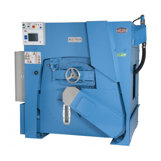
- Page 1 Manual Number: MCWG4M01 Edition (ECN): 2021066 Mechanical Parts and Service 42044SR2, SR3 PELLERIN MILNOR CORPORATION Post Office Box 400, Kenner, Louisiana 70063–0400, U.S.A.
-
Page 3: Table Of Contents
How to Apply and then Release the Brake Quickly..........39 How the Brake Operates on Divided Cylinder Machines ........39 The Second Brake....................40 2 Safety-Related Components & Assemblies.................41 Safety Placard Use and Placement 42031, 42044 SP2/SR2 & SP3/SR3 SINGLE MOTOR ........................42 DRIVE Pellerin Milnor Corporation... - Page 4 How to Do Maintenance on Pulleys and Belts...............70 Typical Steps to Replace Pulleys and Belts............71 ® Examples of Procedures Used at the Milnor Factory to Align Pulleys....72 4 Bearing Assemblies ........................74 Main Bearing and Seal Replacement for Divided Cylinder Machines .........74 Removing the Bearing (Front or Rear)................76...
- Page 5 ....................153 4244SP2 Brake Air Cylinder ......................156 Staphairtrol ...................158 4244SP2, 4244SP2 SM Figures Figure 1 The Bolts in Milnor ® Equipment................14 Figure 2 Apply Threadlocker in a Blind Hole.................19 Figure 3 Apply Threadlocker in a Through Hole..............20 Figure 4 Use heat for disassembly of fasteners with threadlocker..........20 Figure 5 A typical hydraulic brake system................29...
- Page 6 Torque Values for Standard Fasteners with Maximum 5/16-inch Diameters and No Lubricant ......................14 Table 3 Torque Values for Standard Fasteners Larger Than 5/16-inch Diameters and No Lubricant ......................14 Table 4 Torque Values for Plated Fasteners with Maximum 5/16-inch Diameters and No Lubricant ......................15 Pellerin Milnor Corporation...
- Page 7 Table 38 Parts List—Air Chamber Level Switch 42044WR2,WR3,SR2,SR3; 6044WR2,WR3, ................124 SR2, SR3; 72044WR2, WR3, SR2, SR3 Table 39 Parts List—Temperature Probe ..........125 42044SR2, 42044WR2 Table 40 Parts List—Peristaltic Connection ........129 4244SP2, SP3, 4244SP2 SM Table 41 Parts List—Soap Chute ............131...
- Page 8 Table 49 Parts List—Burket Steam Valve ................151 Table 50 Legend – Pneumatic Schematic ..............153 4244SP2 Table 51 Parts List—Pneumatic Schematic ..............155 4244SP2 Table 52 Parts List—Brake Air Cylinder ................157 Table 53 Parts List—Staphairtrol ............159 4244SP2, 4244SP2 SM Pellerin Milnor Corporation...
-
Page 9: General Service Information
1 General Service Information Pellerin Milnor Corporation... -
Page 10: Limited Standard Warranty
General Service Information BMP720097 / 19036 BRUUUM01.1 0000229985 A.3 D.6 12/5/19 11:43 AM Released Pellerin Milnor Corporation... -
Page 11: How To Get The Necessary Repair Components
Email: parts@milnor.com BNUUUU02 / 2020152A BNUUUU02 0000158094 4/6/20 2:44 PM Released Trademarks BNUUUU02.R01 0000158093 A.3 E.2 D.2 4/6/20 2:44 PM Released These words are trademarks of Pellerin Milnor ® Corporation and other entities: Table 1. Trademarks AutoSpot™ GreenFlex™ MilMetrix ®... -
Page 12: Safety - Divided Cylinder And Staph Guard
Keep yourself and others clear of movement areas and paths. � Safety Alert Messages—Cylinder and Processing Hazards BNWVUS03.C03 0000235094 A.3 A.2 1/2/20 2:19 PM Released The following are instructions about hazards related to the cylinder and laundering process. Pellerin Milnor Corporation... -
Page 13: Safety Alert Messages-Unsafe Conditions
Do not operate the machine with any evidence of damage or � malfunction. WARNING: Multiple Hazards — Operating the machine with an inoperative safety device can kill or injure personnel, damage or destroy the machine, dam- age property, and/or void the warranty. Pellerin Milnor Corporation... -
Page 14: Hazards Resulting From Damaged Mechanical Devices
Stop the machine immediately if any of these conditions occur: • ab- � normal whining sound during extract • skidding sound as extract ends • clutches remain engaged or re-engage during extract Pellerin Milnor Corporation... -
Page 15: Careless Use Hazards
Hazards include but are not limited to panic, burns, poisoning, suffo- cation, heat prostration, biological contamination, electrocution, and crushing. Do not enter the cylinder until it has been thoroughly purged, flushed, � drained, cooled, and immobilized. Pellerin Milnor Corporation... -
Page 16: Torque Requirements For Fasteners
The document about the assembly gives the torque requirements for other fasteners. If fastener torque specifications or threadlocker requirements in an assembly document are different from this document, use the assembly document. Figure 1. The Bolts in Milnor ® Equipment... -
Page 17: Table 4 Torque Values For Plated Fasteners With Maximum 5/16-Inch Diameters And No Lubricant
– – 7/16 x 20 1/2 x 13 – – 1/2 x 20 9/16 x 12 – – 9/16 x 18 5/8 x 11 – – 5/8 x 18 3/4 x 10 – – 3/14 x 16 Pellerin Milnor Corporation... -
Page 18: With A Threadlocker
– Table 8. Torque Values if You Apply LocTite 242 The Grade of the Bolt Grade 2 Grade 5 Grade 8 Grade BC Dimension Pound-Feet Pound-Feet Pound-Feet Pound-Feet 5/16 x 18 5/16 x 24 3/8 x 16 Pellerin Milnor Corporation... - Page 19 1-1/4 x 7 1456 1974 2362 3202 2067 2802 – – 1-1/4 x 12 1613 2187 2615 3545 1154 1909 2588 3097 4199 2710 3674 1-3/8 x 6 1-3/8 x 12 1315 2174 2948 3526 4781 – – Pellerin Milnor Corporation...
-
Page 20: Stainless Steel Fasteners
3/4 x 10 3/4 x 16 7/8 x 9 7/8 x 14 1 x 8 1 x 14 1-1/8 x 7 1-1/8 x 12 1-1/4 x 7 1-1/4 x 12 1261 1204 1-1/2 x 6 1-1/2 x 12 Pellerin Milnor Corporation... -
Page 21: Preparation
Apply the threadlocker only to the areas where the fastener threads and the mating threads engage. Figure 2. Apply Threadlocker in a Blind Hole Application Coverage Legend A... No threadlocker here B... Apply here C... Fill all space with threadlocker Pellerin Milnor Corporation... -
Page 22: Blind Holes
For low-strength and moderate-strength threadlocker, disassemble with hand tools. Figure 4. Use heat for disassembly of fasteners with threadlocker. Legend Apply Heat to a Small Area A... How to apply heat to a small fastener B... How to apply heat to a large fastener Pellerin Milnor Corporation... - Page 23 This page intentionally blank...
-
Page 24: General Assembly
2/17/20 1:59 PM Released General Assembly 6 Sheets 4244SP2 SM Clean Side Legend A... Peristaltic connection, see BPWG4C01 B... Suspension cylinders, see BPWVUJ01 C... Soapchute, see BPWG4C02 D... Idler shaft bearings, see BPWG4B03 E... Staphairtrol, see BPWG4P02 Pellerin Milnor Corporation... - Page 25 General Service Information General Assembly 6 Sheets 4244SP2 SM Soil Side Legend F... Main bearing, see BPWG4B01 Pellerin Milnor Corporation...
- Page 26 6 Sheets 4244SP2 SM Legend G... Brake assembly, see BPWG4I04 H... Water inlets, see BPWG4W02 J... Excursion switch, see BPWG4Z01 K... Jackshaft, see BPWG4I03 M... Cooldown, see BPWG4W03 N... Drive chart, see BPWG4I01 P... Staphairtrol, see BPWG4P02 Pellerin Milnor Corporation...
- Page 27 (items 19–22) are designed for left and right of the machine, using this rule. Rear view — Cleanside Legend L... Left side Q... 60 places R... Right side S... Shell doors, see BPWG4D01 T... Cylinder doors, see BPWVUD02 U... Interlock plunger, see BPWG4D02 Pellerin Milnor Corporation...
- Page 28 General Service Information General Assembly 6 Sheets 4244SP2 SM Pellerin Milnor Corporation...
- Page 29 EXTRUSION SHELL CS RT 42SG 02 18781C EXTRUSION FRAME CS LF 42SG 02 18781D EXTRUSION FRAME CS RT 42SG 15U320 FLATWASHER(USS STD) 3/4" UNPLT 02 175032 CLAMP BOOT 60142 +60SG 15P175 TRDCUT-F HXHD 1/4-20UNC2AX1/2 Y2 15797 BOOT ASSEMBLY 42SGH OUR MATL Pellerin Milnor Corporation...
-
Page 30: Disk Brake Maintenance
TIP: During parts of this procedure when you open up the calipers or hydraulic lines, put a cloth under the calipers to catch hydraulic fluid and parts that will fall. For safety, fully remove spilled hydraulic fluid after brake maintenance. This will help you easily identify leaks. Pellerin Milnor Corporation... -
Page 31: Figure 5 A Typical Hydraulic Brake System
4. Hydraulic reservoir 5. Rotor disk 6. Hydraulic inlet 7. Valves to drain fluid and bleed the brake 8. Hydraulic cylinder 9. Bolts to attach the caliper (Figure , item 1) The hydraulic cylinder and the caliper Pellerin Milnor Corporation... -
Page 32: The Inspection Of The Brake
Supply electrical power to the machine. 4. Examine the condition of all of the brake system. a. Make sure that brake mounting components are tightly installed. b. Make sure that fittings are tight. Make sure that there are no leaks. Pellerin Milnor Corporation... -
Page 33: How To Do A Friction Pad Replacement
7. Put the caliper halves in their positions on the brake assembly. Tighten the mounting bolts to 30 foot-pounds (41 Newton-meters). 8. Bleed the brake. See : How to Change Hydraulic Fluid and Remove (Bleed) Air from the Brake Circuit , page 33 9. Supply electrical power to the machine. Pellerin Milnor Corporation... -
Page 34: How To Do A Caliper Overhaul
(Figure 6 , item 10). When you disconnect the calipers, hydraulic fluid can flow from the hole at the connec- tion O-rings. Air can get in the line. After you connect the calipers, you must bleed the system. Pellerin Milnor Corporation... -
Page 35: Circuit
CAUTION: Risk of injury and damage — This procedure releases pressurized brake fluid. Keep brake fluid out of your eyes and mouth. Wear eye protection. � Follow procedures carefully to prevent damage to the face of the disk � or the pistons. Pellerin Milnor Corporation... -
Page 36: Figure 7 Pumps Used To Remove Hydraulic Fluid Quickly
Fluid and Remove (Bleed) Air from the Brake Circuit , page 33 Figure 7. Pumps Used to Remove Hydraulic Fluid Quickly Alternative Pumps for Suction of Hydraulic Fluid Legend 1. A manual suction pump 2. The Vacula suction pump uses compressed air and holds used hydraulic fluid. Pellerin Milnor Corporation... -
Page 37: Cylinder
8: Typical Tools to Remove Air (Bleed) Brakes and Used Hydraulic Fluid, page a. Fill the reservoir with new DOT 3 brake fluid. When you do the remaining steps, continue to add new fluid to the reservoir. Do not let the reservoir become more than half empty. Pellerin Milnor Corporation... -
Page 38: Figure 9 The Connection Between The Brake Cylinder And The Air Cylinder
1. The brake cylinder 2. The rod for the brake cylinder 3. The rod for the air cylinder 4. The air cylinder 5. Two nuts to lock the rods together 6. The slot to see the nuts Pellerin Milnor Corporation... -
Page 39: Figure 10 The Adjustment Between The Brake Rod And The Air Cylinder
Second mark—one possible position—the brake applied M2b. Second mark—a different position—the brake applied AT.. Air tubing (See Figure 5: A typical hydraulic brake system, page 29 , item1). Air releases the brake. S... Spring applies the brake Pellerin Milnor Corporation... -
Page 40: Operation Of Brake Systems
, item 5). (Figure 10: The Adjustment be- tween the Brake Rod and the Air Cylinder, page 37 , item C,D) NOTE: If electrical power or compressed air is missing, hydraulic pressure will ap- ply the brake. Pellerin Milnor Corporation... -
Page 41: How To Release The Brake For Machines With A "Brake Release" Output
(85 -100 PSI) (5.95 - 07.0 kg/cm-cm) 2. Tubing for air that applies the second brake (10 – 12 PSI) (0.7-0.84 kg/cm-cm) • On divided cylinder machines, two pair of air tubes connect to different ends of the air cylinder. Pellerin Milnor Corporation... -
Page 42: The Second Brake
Make sure that you adjust the air pressure of the second brake (Figure 11: A Typical First and Second Brake on a Divided Cylinder Machine, page 39 , item 2) to 10 – 12 PSI (0.7-0.84 kg/cm-cm). Pellerin Milnor Corporation... -
Page 43: Safety-Related Components & Assemblies
2 Safety-Related Components & Assemblies Pellerin Milnor Corporation... -
Page 44: Safety Placard Use And Placement
NOTICE: Replace placard immediately, if removed or unreadable. Approximate loca- tions of placards are shown. If aluminum placard, mounting holes are provided on machine. Use #8 self-tapping screws. Legend A-A. Rear (unload end) view B-B. Left view C-C. Front (Load end) view D-D. Right view Pellerin Milnor Corporation... - Page 45 Used In Item Part Number Comments Reference Assemblies none Components 01 10627A NPLT:DIV-CYL/STAPH WARN-TCATA 01 10377A NPLT:ELEC HAZARD LG-TCATA 01 10689A NPLT:BELT HAZARD SM TCATA 01 10648A NPLT:GEAR HAZARD-TCATA 01 10685A NPLT:BURN HAZARD WARN-TCATA 01 10699B NPLT:SERV HZRD-ALUM-TCATA Pellerin Milnor Corporation...
-
Page 46: Safety Placard Use And Placement Iso
NOTICE: Replace placard immediately, if removed or unreadable. Approximate loca- tions of placards are shown. If aluminum placard, mounting holes are provided on machine. Use #8 self tapping screws. Legend A-A. Rear (unload end) view B-B. Left view C-C. Front (load end) view D-D. Right view Pellerin Milnor Corporation... - Page 47 "all" in the "Used In" column. The numbers shown in the "Item" column are those shown in the illustrations. Description/Nomenclature Used In Item Part Number Comments Components 01 10627X NPLT:DIVCYL SG WARNG FRT ISO 01 10377 NPLT:WARNING 4X4 01 10649X NPLT:HOT BEHIND CVR WARN-ISO 01 10628X NPLT:NONTILT W/E WARNING SIDE 01 10648X NPLT:ACTUATED VALVE WARN-ISO Pellerin Milnor Corporation...
-
Page 48: Vibration Safety Switch Adjustments
Adjustments BNWUUM01.C03 0000250240 A.3 C.2 B.2 11/7/19 10:43 AM Released When the machine leaves Milnor ® , the actuator arm is tie-wrapped to prevent damage (except on 30015, 30020, and 30022 models). This tie wrap must be removed after the machine is set in- to position but before the machine is operated. -
Page 49: Figure 12 Vibration Switch
(e.g., ones where the sub-soil is mushy or springy or otherwise not as desirable), consider- ably greater machine movement will occur for a given degree of out-of-balance, in which case a less sensitive vibration switch setting may be indicated. Pellerin Milnor Corporation... -
Page 50: Vibration Safety Switch
* ASSY-VIBRATION SWT=LG CONTR Components 02 02038 PLATE INSULATING SMALL 9NOV51 15P008 TRDCUT PANHD 6-32X1 NIKSTL +WA 02 15119 BRACKET=VIBSW CAD 09R020 SWITCH NC VIBR#WZ-2RW84429-P52 03 01059 VIBSWITCH CLAMP CADSTL 03 01058 VIBSWITCH WEIGHT-CADSTL 15P101 TRDCUT-F PANHD 8-32X3/8 NIKSTL Pellerin Milnor Corporation... -
Page 51: Drive Assemblies
3 Drive Assemblies Pellerin Milnor Corporation... -
Page 52: Drive Chart
BPWG4I01 / 2019513 BPWG4I01.1 0000265687 A.3 A.5 12/17/19 1:28 PM Released Drive Chart 5 Sheets 4244SP2 SM (Single Motor) Legend B... Front jackshaft pulley F... Rear jackshaft pulley G... 3 rib belt, uses 2 H... Motor pulley Pellerin Milnor Corporation... - Page 53 4244SP2 SM (Single Motor) Front Soil Side Rear Clean Side Legend A... Front main pulley B... Front jackshaft pulley C... Front idler pulley D... Rear main pulley E... Rear idler pulley J... Main shaft K... Idler shaft Pellerin Milnor Corporation...
- Page 54 Drive Assemblies Drive Chart 5 Sheets 4244SP2 SM (Single Motor) Legend A... Front main pulley B... Front jackshaft pulley C... Front idler pulley L... Key comes with bushing Pellerin Milnor Corporation...
- Page 55 Drive Assemblies Drive Chart 5 Sheets 4244SP2 SM (Single Motor) Legend D... Rear main pulley E... Rear idler pulley Pellerin Milnor Corporation...
- Page 56 56110B6SF VPUL 6B11.0/A10.6 (SF) TYPE QD 56Q2ASF 2.0" BUSHING,VPUL QD TYPE "SF" 56VB083X VBELT BX83 RAWEDGE COG 56070B6SF VPUL 6B7.0/A6.6 (SF) TYPE QD 56Q2DSF 2+3/16" BUSH VPUL QD TYPE SF 02 15794 KEY-1/2X2+1/2 4231-4244SGH 02 175121 KEY=5/8SQ Pellerin Milnor Corporation...
-
Page 57: Drive Base
Drive Assemblies BPWG4I02 / 2019213 BPWG4I02.1 0000266390 A.3 A.4 12/17/19 2:26 PM Released Drive Base 5 Sheets 4244SP2 SM (Single Motor) Legend F... Jackshaft Pellerin Milnor Corporation... - Page 58 5 Sheets 4244SP2 SM (Single Motor) Detail D Detail E Legend A... Front jackshaft B... Rear jackshaft C... Pillowback bearing D... See detail D E... See detail E G... Upper H... Lower J... Uses 3 K... As required Pellerin Milnor Corporation...
- Page 59 Drive Assemblies Drive Base 5 Sheets 4244SP2 SM (Single Motor) Pellerin Milnor Corporation...
- Page 60 HXNUT 1/2-13UNC2B SAE ZINC GR2 15U490 FLTWASH 1+1/2X17/32X1/4 ZINC 15K180 HXCAPSCR 1/2-13UNCAX2 GR5 ZINC 15K151 HXCAPSCR 1/2-13UNC2AX1.25 GR5 15K173A HXCAPSCR 1/2-13UNC2AX1.75 GR5 02 19283 NUT=1/2-13UNCX1+1/2SQ SPEC 15K162 HXCAPSCR 1/2-13UNC2AX1.5 GR5 P 02 11603C WASHER DBLR=1.5W/CUTOFF SIDE 15P200 TRDCUT-F HXWASHD 3/8-16X3/4NIK Pellerin Milnor Corporation...
- Page 61 HYDFIT 1/8"-90 ALEMITE 1613-B 5SCC0CBE NPT COUP 1/8 BRASS 125# 103A-A 5N0C03AG42 NPT NIP 1/8X3 TBE GALSTL SK40 15D125 HXTAPSCR 5/8-11X4-FLTHRD GR5 15U315 LOKWASHER MEDIUM 5/8 ZINCPL 15G238 HXNUT 5/8-11UNC2B SAE ZINC GR2 15U393 FLTWASH 1" HARD ASTM F436 Pellerin Milnor Corporation...
-
Page 62: Jackshaft
A.3 B.6 4/8/20 3:52 PM Released Jackshaft 2 Sheets 4244SP2 SM (Single Motor) Legend A-A. Detail view A–A B-B. Detail view B–B C... Insert all 1/2” fasteners hand tight, then torque in the sequence shown, front and back. Pellerin Milnor Corporation... - Page 63 15U180 LOCKWASHER MEDIUM 1/4 ZINCPL 15K030 HEXCAPSCR 1/4-20UNC2X1/2 GR5 Z 15K041 HXCAPSCR 1/4-2OUNC2AX1 GR 5 ZI 02 19195 RING=GREASE SLNGR JKSHFT WHT 51A001 ADAPTER 1/8 PT BRASS 5SL0CBEC NPTELB 90DEG STRT 1/8 BRASS125 20C007G THDLOCKSEAL LCT24231 RMUBL50CC Pellerin Milnor Corporation...
-
Page 64: Brake Assembly
Drive Assemblies BPWG4I04 / 2020082 BPWG4I04.1 0000266631 A.3 B.3 2/17/20 2:10 PM Released Brake Assembly 3 Sheets 4244WP2/WR2, 4244SP2/SR2 Legend G... 4 places H... 6 places J... Bushing includes hardware K... See figure 1 L... See BPWVUP01 Pellerin Milnor Corporation... -
Page 65: Figure 13 Exploded View Of The Caliper And Repair Kit Components
54KC7964R1 ORING EPR #220 W. C. BRANHAM #4000-1059 PART OF KIT — 4A 54KC7963R1 PUCK/FRICTION PAD=W. C. BRANHAM #4000-1052 PART OF KIT — 4A 54KC7963R2 PANHD SCREW - W. C. BRANHAM #4000-1118 PART OF KIT — 4A Pellerin Milnor Corporation... - Page 66 LOKWASHER REGULAR 1/2 ZINC PLT 15K041E SKCPSCR 1/4-20X1+1/4"BLK 15G166A HXLOKNUT NYL1/4-20 UNC2A STL/Z 15P200 TRDCUT-F HXWASHD 3/8-16X3/4NIK 56Q1RSK 1+7/8" BUSH VPUL QD TYPE SK 15K065 HEXCAPSCR 5/16-18UNC2AX1 GR5 Z 15U210 LOKWASHER MEDIUM 5/16 ZINCPL 15G185 HXNUT 5/16-18UNC2B SAE ZINC GR Pellerin Milnor Corporation...
-
Page 67: Drive Pulley And Belt Maintenance
BNUUUM02.C03 0000274611 A.3 A.4 A.2 2/4/20 8:08 AM Released Replace a pulley if: • the grooves have burrs, cracks, or worn areas that can cause damage to the belts. • the belts touch the bottom of the groove at any point (Figure 15 Pellerin Milnor Corporation... -
Page 68: Pulley And Shaft Position
2. Not aligned: Pulley grooves are in different planes and shafts are not parallel. 3. Not aligned: Pulley shafts are not parallel (not at the same slope). 4. Aligned: Pulley grooves are in the same plane and shafts are parallel. Pellerin Milnor Corporation... -
Page 69: Keep Run-Out In Tolerance
(0.1 mm for each dm) of the pulley diameter. 2. Radial run-out. This pulley is not circular. This condition must be less than 10 mils (0.25 mm). 3. Bushing 4. Shaft 5. A circle 6. Bushing bolts 7. Sheave Pellerin Milnor Corporation... -
Page 70: Belt Requirements
Slippage occurs if belts are not aligned (see ) or by incorrect tension explained in . Slippage can cause belts to become too hot. Belts must not have a temperature more than than 140F (60° C). TIP: The belt storage area must be cool and dry with no sun light. Pellerin Milnor Corporation... -
Page 71: Tension Of Belts
All belts will become longer after a short time. A V-belt will move down in the grooves of the pulleys. These conditions will cause the tension to decrease. When you do scheduled maintenance, examine the belts for correct tension. With operation, belts become longer. Pellerin Milnor Corporation... -
Page 72: The Pulleys Must Stay Aligned When You Adjust The Belt Tension
Related Data Torque wrench Make the bushing bolts the same Figure 18 , item 2 torque to get the minimum axial run-out. Laser, straight Align pulleys Tools are listed in order of preference. edge, or string Figure 22 Pellerin Milnor Corporation... -
Page 73: Typical Steps To Replace Pulleys And Belts
If the belts slip, increase belt tension with the machine shut down and power removed. Then test again. Make sure that the machine is safe before you put it into reg- ular operation. Pellerin Milnor Corporation... -
Page 74: Examples Of Procedures Used At The Milnor ® Factory To Align Pulleys
Drive Assemblies Examples of Procedures Used at the Milnor ® Factory to Align Pulleys BNUUUM02.C12 0000274686 A.3 A.4 3/6/20 4:49 PM Released Figure 22. Use a straight edge, a string, or a laser to make sure that all pulleys are in the same plane. - Page 75 Figure 24. Dial indicator used to find the axial and radial run-out of a pulley. Legend Axial Run-out (1) Radial Run-out (2) 1. Dial indicator in position to measure axial run-out 2. Dial indicator in position to measure radial run-out Pellerin Milnor Corporation...
-
Page 76: Bearing Assemblies
The front and rear bearings are each protected from contamination from wash water by three spring loaded, lip type seals and a shaft seal leak off cavity (that carries off any water that leaks past the main water seals) as shown in Figure 25 Pellerin Milnor Corporation... - Page 77 A set of guide rods, a seal sleeve setting fixture and a bear- ing setting fixture are required for reinstallation of the housing. These tools are available for rental or purchase from the Milnor ®...
-
Page 78: Removing The Bearing (Front Or Rear)
4. Slide the bearing off of the shaft and if it is to be reused, place it on a clean surface and cover with a clean, lint free cloth. Figure 26. Connection From Hydraulic Pump to Assist in Bearing Removal Pellerin Milnor Corporation... -
Page 79: (Front Or Rear)
BNWVUM02.T02 0000278618 A.3 A.5 3/12/20 11:54 AM Released ® These procedures require the use of a pulling fixture and guide rods available from the Milnor factory. With the bearing cover (or shaft seal holder) and the bearing removed, proceed as follows: 1. -
Page 80: Precautions For Bearing Replacement
Replace with new o-rings if the old ones are worn. 4. Press new seals into the bearing housing. You may gently work the seals in with a mallet and metal drift as shown in Figure 29 Pellerin Milnor Corporation... -
Page 81: Installing Seals In Bearing Housing
. Once the hous- ing is far enough into the shell to support itself, place any shims back into position between the housing and the shell. Remove, then replace guide rods if required to place shims under bearing housing pads. Pellerin Milnor Corporation... -
Page 82: Installing The Bearing Housing Setting Fixture Onto Housing (42" Ma- Chine Shown)
: Measuring Unmounted Clearance and Setting Bearing (Front or Rear), page 81 even if both the front and rear bearings are being replaced. Once the rear bearing is installed, the bearing housing replacement procedures may then be repeated for the front (soil side) bearing housing. Pellerin Milnor Corporation... -
Page 83: Measuring Unmounted Clearance And Setting Bearing (Front Or Rear)
Rear) BNWVUM02.T04 0000278712 A.3 A.5 3/12/20 11:54 AM Released ® The bearings used on Milnor washer and dye extractors are the very best anti-friction devices available for these applications. However, the anti-frictional characteristics of the bearings will be reduced if they are not properly installed. It is of critical importance when installing these ta-... - Page 84 Contact your bearing supplier for an exchange. NOTE: The clearances listed in the chart are industry standards and therefore apply to all brands of bearings supplied by Milnor ® . If other sources of bearings are used, re- fer to the manufacturer’s instructions for proper clearances.
-
Page 85: Tightening Bearing(S) (Front And/Or Rear)
3. If one row of rollers is tight but the other has measurable clearance, tap lightly on the end of the shaft nearest the tight row of rollers to cause the shaft to shift axially and equalize the roll- er loading. Adjust the bearing tightness to achieve the internal clearance previously calculated. Pellerin Milnor Corporation... -
Page 86: Tightening The Bearing Lock Nut (42" Machine Shown)
Also, make sure that the seal lip does not turn over as it passes over rough areas. Pellerin Milnor Corporation... - Page 87 This page intentionally blank...
-
Page 88: Main Bearing Assembly
Main Bearing Assembly 4 Sheets 42031, 42044 CP2/CP3, NP2/NP3, WP2/WP3, SP2/SP3, DA2/DA3, DP2/DP3 Legend A-A. Section view, Non Staph-Guard models B-B. Section view C-C. Section view D-D. Section view G-G. Section view, Staph-Guard machines only K... Bearing L... Seal Pellerin Milnor Corporation... - Page 89 Bearing Assemblies Main Bearing Assembly 4 Sheets 42031, 42044 CP2/CP3, NP2/NP3, WP2/WP3, SP2/SP3, DA2/DA3, DP2/DP3 Legend B-B. Section view C-C. Section view E-E. Section view F-F. Section view H-H. Section view J-J. Section view K... Bearing L... Seal Pellerin Milnor Corporation...
- Page 90 24GA ADJWASH=BRGHOUS ZINC PL 5N0C03AG42 NPT NIP 1/8X3 TBE GALSTL SK40 X2 15539 CARRIER=REAR BRG+SEAL X2 15702 RETAINER=REAR BRG+SEAL 60C152C ORING 4+7/8IDX1/8CS BUNA70#249 24S005 SEAL 2.25 X 3.0 X .375 SS BUNA 15K095 HXCPSCR 3/8-16UNC2AX1 GR5 ZINC Pellerin Milnor Corporation...
- Page 91 "all" in the "Used In" column. The numbers shown in the "Item" column are those shown in the illustrations. Description/Nomenclature Used In Item Part Number Comments X2 15683 SUPPORT-SHAFT=2/42WEHU 51P013 PLUG HXCNTRSUNK 1/4"BRASS X2 15746 RETAINER=BRG=SOILSD:C2-15702 Pellerin Milnor Corporation...
-
Page 92: Autospot
Detail view B... Typical 3 places C... Rear main pulley, see Drive chart D... Target E... Pocket 1 F... Pocket 2 G... Speed sensor H... Typical 8 places J... Rear main bearing, see BPWG4B01 K... Clean side Pellerin Milnor Corporation... - Page 93 02 19179A SWITCH MNT PLATE OUTER 09RPS07RDS 7MM SENSING RECTANGULAR SHLD 02 19186B SHT/COLLAR PROX TARGET 42" SG 02 19186A PROX TARGET 60" SM DRIVE X2 15747 SEAL HOLDER SGL/MTR 42" SG 15K018 SKCPSCR 10-24 UNC 3X3/8 BLK Pellerin Milnor Corporation...
-
Page 94: Idler Shaft Bearing
Idler Shaft Bearing 2 Sheets 42031, 42044SP2/SP3 & 4244SP2 SM Legend A... Soil side, floating side B... Clean side, lock side C... Lower right X-brace D... 1/16” all around E... Route tubes to grease fittings on lower right brace Pellerin Milnor Corporation... - Page 95 HEXCAPSCR 1/4-20UNC2X1/2 GR5 Z 15U180 LOCKWASHER MEDIUM 1/4 ZINCPL 54M020 GREASEFIT 30DEG 1611-B ALEMITE 5SB0E0CBEO NPTHEXBUSH 1/4X1/8 BRASS 125# 53A007B BODYFEMCON.25X.25COMP#B66A-4B 53A008B BODYMALECON.25X.25COMP#B68A-4B 53A500 SLEEVE DELRIN 1/4"OD#60PT-4 53A059A NUT 1/4"BR.HOLYOKE AND #61A-4 53A501 TUBE INSERT .163"OD #63PT-4-40 Pellerin Milnor Corporation...
-
Page 96: Idler Shaft Bearing Replacement
When it is known that only the soil side bearing is bad, it may be changed by the above men- tioned hydraulic method without damaging the clean side bearing. Pellerin Milnor Corporation... -
Page 97: How To Install New Bearings
Check to make sure bearing housing mounting bolts are tight. 5. Lubricate the bearing before operation. Follow the instructions for bearing lubrication as out- lined in section “Tightening Bearing(s) (Front and/or Rear)” found in “Main Bearing and Seal Replacement for Divided Cylinder Machines”. Pellerin Milnor Corporation... -
Page 98: Frame, Pivots And Suspension
Suspension Adjustments for Divided Cylinder Machines BNWVUM01.C01 0000277938 A.3 B.2 2/5/21 9:25 AM Released The suspension system on Milnor ® Hydro-cushion™ machines is adjusted and thoroughly tested at the factory. It should not require subsequent adjustment unless the machine is distorted during shipment or installation or unless some component of the system, such as a Hydro-cushion™... -
Page 99: Shell Hanging Dimensions And Adjustment Procedures
NOTE: Only slight deviations from the dimensions shown should be used to level the shell. If large deviations are required, this may indicate that the frame is out of level. If so, this condition must be corrected before attempting to level the shell. Pellerin Milnor Corporation... -
Page 100: Figure
4 1/8" (105) 42031SG 4 1/8" (105) 44044WE 4 1/8" (105) 42044SG 4 1/8" (105) 60031WE 3 5/8" (92) 60031SG 3 5/8" (92) 60044WE 3 5/8" (92) 60044SG 3 5/8" (92) 72044SG 3 3/4" (95) 72044WE 3 3/4" (95) Pellerin Milnor Corporation... -
Page 101: Push-Down Travel Dimensions And Adjustment Procedures
4. Set the Master switch to manual, causing the shell to push-down. Figure 39. Push-down Travel Adjustment: 42" Div-cyls (42" Staph Guard ® Legend A... Push-down housing (rest pads and brackets within) B... Rubber rest pad (shim between rubber pan and metal pan) C... Gaps must be equal. Pellerin Milnor Corporation... -
Page 102: 60" Divided Cylinder Machines
2. Measure the gap between the top of the ring weldment and the bottom of the mounting brack- et, at each location. Pellerin Milnor Corporation... -
Page 103: Ring Weldments
(see the right side of Figure 40: Ring Weldments, page 101 ). Any extra shims may be stacked on the top side of the mounting bracket plate to which the ring weld- ment is attached. Pellerin Milnor Corporation... -
Page 104: Hold Down Adjustment
N1.. Be sure shell does not bottom on basepad, there must be clearance at this point. Check each corner N2.. Place shims here to adjust ring weldment so that all four corners seat simultaneously. Pellerin Milnor Corporation... - Page 105 SHIM=HOLDOWN 1/4"THICK 03 06216B SHIM=HOLDOWN 10GA THICK 03 06216C SHIM=HOLDOWN 16GA THICK W3 06406 *RING=HOLD DOWN CENT-STAMPED 15G238 HXNUT 5/8-11UNC2B SAE ZINC GR2 15U315 LOKWASHER MEDIUM 5/8 ZINCPL 15D125 HXTAPSCR 5/8-11X4-FLTHRD GR5 15K300 HXCAPSCR 1-8UNC2A X4.5 SAE GR5 Pellerin Milnor Corporation...
-
Page 106: Pushdown
Frame, Pivots and Suspension BPWG4J01 / 2020125 BPWG4J01.1 0000267458 A.3 A.5 3/19/20 8:27 AM Released Pushdown 2 Sheets 4244SP2 SM LEFT FRONT AIRMOUNT Legend A... Shellfront B... Restpad C... Shims D... See Pushdown travel dimensions and adjustment procedures, BNWVUM01. Pellerin Milnor Corporation... - Page 107 5N0E02KG42 NPT NIP 1/4X2.5 TBEGALSTL SK40 96M055 DELTROL QUICK EXHAUST VLV.1/4" 27A005 MUFFLER 3/8" BANTAM B38 53A031XB BODY-EL90MALE.25X25 #269C-4-4B 15K095 HXCPSCR 3/8-16UNC2AX1 GR5 ZINC 15U240 FLATWASHER(USS STD) 3/8" ZNC P 02 15450 RESTPAD(RUBBER) 4/42WEHU 02 15921 SHIM=HOLDDOWN=42"WEHU Pellerin Milnor Corporation...
-
Page 108: Suspension Cylinder Assemblies
Frame, Pivots and Suspension BPWVUJ01 / 2020032 BPWVUJ01.1 0000267484 A.3 A.5 1/13/20 4:53 PM Released Suspension Cylinder Assemblies 3 Sheets 42031,42044,52038,60044,72044 Legend A... Oil level B... Shell Pellerin Milnor Corporation... - Page 109 HXCAPSCR 1-8UNC2AX5.5 SAEGR5 Z 15G255A SQNUT 1-8UNC2B SAE ZINC GR2 15U400 LOCKWASHER MEDIUM 1" ZINCPL 60C159A ORING 5.475ID 1/4CS BN70 #433 24S040 SEAL URETHNE 1-7/16 2.25 13/32 M2 18690 LOWER CAP=HYDROCYL 02 18839A MACHBUSH HYDRCYL CAP #433-OR Pellerin Milnor Corporation...
- Page 110 LOKWASHER REGULAR 1/2 ZINC PLT 15G231 HXFINJAMNUT 1/2-13UNC2B ZINC G 02 18534 HOLDPLATE= BALLBRUSH ZNC/CAD 02 18795A WASH-TIMING=HYDRO CYL 45DEG USE ONE 02 18795B WASH-TIMING=HYDRO CYL 75DEG USE ONE 15K191 HXCAPSCR 1/2-13UNC2AX2.5 GR5 Z AVH52001 ASSY=OILFIL SPOUT 72HYD CYL Pellerin Milnor Corporation...
- Page 111 This page intentionally blank...
-
Page 112: Suspension Cylinder Locations
2 Sheets Legend C1.. Cylinder #1 C2.. Cylinder #2 C3.. Cylinder #3 C4.. Cylinder #4 E... Front or soil side J... A letter is stamped on the end of the upper bolt to designate the cylinder assembly. Pellerin Milnor Corporation... - Page 113 52038 60044 72044 72044 42031 SP2, 42044 CP2, CP2,NP2, NP2,WP2, SP2/3; WP2 SM, WTL,WTN, WP2/3 SM WP2,WP3, SP2,SP3 WP2,WP3 WP3,D7P SR2/3 WP3 SM SP2/3 SM SR2/SR3 WR2,WR3 WR2/3 SR2/3 Cylinder #1 Cylinder #2 Cylinder #3 Cylinder #4 Pellerin Milnor Corporation...
-
Page 114: Shell And Door Assemblies
6 Shell and Door Assemblies Pellerin Milnor Corporation... -
Page 115: Shell Doors 42031/42044Cp2,Np2,Wp2,Wp3,Sp2,Sp3, 4244Sp2 Sm
Shell and Door Assemblies BPWG4D01 / 2020035 BPWG4D01.1 0000267634 A.3 A.4 1/16/20 8:53 AM Released Shell Doors 3 Sheets 42031/42044CP2,NP2,WP2,WP3,SP2,SP3, 4244SP2 SM Pellerin Milnor Corporation... - Page 116 X2 15016 DOOR HINGE MACHINED 6.218 LG W2 15034 *BAR DOOR LOCKING WELD W2 15763 *BAR DOOR INTLK WLMT-SG ONLY 02 15633S ADJPLATE=DOORLATCH SS SA 15 028 * DOOR LATCH ASSY-DIVCYLS 03 64039D COVER PLATE HANDWHEEL SCREW Pellerin Milnor Corporation...
- Page 117 "all" in the "Used In" column. The numbers shown in the "Item" column are those shown in the illustrations. Description/Nomenclature Used In Item Part Number Comments 54JH13125B HINGE COL SPLIT 3.12 FL TOP 02 10391A COVER STRIP=MICRO SW #10 Pellerin Milnor Corporation...
-
Page 118: Door Latch
"all" in the "Used In" column. The numbers shown in the "Item" column are those shown in the illustrations. Description/Nomenclature Used In Item Part Number Comments Reference Assemblies SA 15 028 Assembly, Door latch Components 02 15105 RETAINER RING 02 15297 STRIKER 02 15298 CYLINDER 02 15836 SPRING 15H090 60C122 O-RING, 1”X1/8 60C128 O-RING, 1+3/8X1/8 Pellerin Milnor Corporation... -
Page 119: Installation Door Switches
"all" in the "Used In" column. The numbers shown in the "Item" column are those shown in the illustrations. Description/Nomenclature Used In Item Part Number Comments Reference Assemblies AD 15 042A DOOR INTERLOCK SWITCH INSTAL AD 15 079 DOOR INTERLOCK ASSY S/S <> Components 09R012STDG * 09R012 +MOUNTING HDWRE+INST 09RM02212S CAPSW 12' 180DEG ROLLER SILVER Pellerin Milnor Corporation... -
Page 120: Cylinder Assembly
Shell and Door Assemblies BPWVUD01 / 2020042 BPWVUD01.1 0000267727 A.3 A.4 1/20/20 9:33 AM Released Cylinder Assembly 2 Sheets 42044WP2, NP2, CP2, SP2 Legend A-A. Section view B... See BPWVUD02 Pellerin Milnor Corporation... - Page 121 "all" in the "Used In" column. The numbers shown in the "Item" column are those shown in the illustrations. Description/Nomenclature Used In Item Part Number Comments Components ACA16WE2B * CYL ASSY=4244WE2 304L TUNNL 42044WP2,CP2,NP2 ACA16SG2B * CYL ASSY=4244SG2 304L TUNNL 42044SP2 SA 15 103 * CYLDOOR ASSY,STAMPED =42U Pellerin Milnor Corporation...
-
Page 122: Cylinder Doors
Shell and Door Assemblies BPWVUD02 / 2020042 BPWVUD02.1 0000267837 1/20/20 9:19 AM Released Cylinder Doors 2 Sheets 42031/42044 CP2,CP3,NP2,NP3,WP2,WP3,SP2,SP3,DA3; 4244WP2 SM,WP3 SM, SP2 SM Legend A-A. Detail View A–A B-B. Detail View B–B C-C. Detail View C–C Pellerin Milnor Corporation... - Page 123 02 15823 HALFHINGE-2/42"WEHU-302 SS 02 15829 PIN=HINGE 1/4" 15G168 SQNUT 1/4-20UNC2 SS18-8 15U181 LOCKWASHER MEDIUM 1/4 SS18-8 15K031 BUTSOKCAPSCR 1/4-20X1/2 SS18-8 15G170 HEXNUT 1/4-20UNC2 SS18-8 15N174 HXCAPSCR 1/4-20UNC X5/8SS18-8 15J008H BUTTON HD RIVET 3/16 X 1/2" SS Pellerin Milnor Corporation...
-
Page 124: Control And Sensing Assbmlies
7 Control and Sensing Assbmlies Pellerin Milnor Corporation... -
Page 125: Excursion Switch
Item Part Number Comments Reference Assemblies E03 33100A EXCURSION SWITCH ASSY 42SGH Components 09R008ASTD * 09R008A+MOUNTING HDWRE+INST 02 15783A *PLATE=EXCURSION SW MTG 02 10391 COVER STRIP=MICRO SW #6-8 02 15789A BKT=EXCURSION SWITCH=SGU 02 15605E ACTUATOR=EXCURSION SW 42SG-SIG Pellerin Milnor Corporation... -
Page 126: Air Chamber Level Switch
NPT 90D STREET 3/4X1/2 GAL150# 96DB0PNA HOSEBIBB 3/4" MALEINLT 45DEG. ACETAL 60E005 TUBING BLK.POLY.5/160DX3/16ID 51V010A TEE 1/8"BRSEXTR BLOCTYP#2203P2 51E502A HOSESTEM BRASS 1/8MPT X3/16 5SP0CBEHS NPT PLUG 1/8 HXCTRSNK BRASS 60E004NA TUBING CLEAR PVC 3/16"IDX5/16"OD 08BNLTT LEVEL TRANSDUCER BD->TEST Pellerin Milnor Corporation... -
Page 127: Temperature Probe
A.3 A.4 1/21/20 11:26 AM Released Temperature Probe 1 Sheet 42044SR2, 42044WR2 42044SR2 42044WR2 Table 39. Parts List—Temperature Probe Find the assembly for your machine and the letter shown in the "Item" column. The components for your machine will show this letter or the word "all"... -
Page 128: Chemical Supply Devices
8 Chemical Supply Devices Pellerin Milnor Corporation... - Page 129 This page intentionally blank...
-
Page 130: Peristaltic Connection
Chemical Supply Devices BPWG4C01 / 2020045 BPWG4C01.1 0000268020 A.3 A.4 1/23/20 11:50 AM Released Peristaltic Connection 2 Sheets 4244SP2, SP3, 4244SP2 SM Pellerin Milnor Corporation... - Page 131 03 25267E PERISTALTIC MOUNTING BRACKET AWL64005A ASSY=PARASTALTIC CONNECT 60 5SL2AP8K NPT EL45DEG 2"PVC SH80 FPTXFPT 51AB2AN2AA HOSE INSERT X MPT 2"PVC40 27A072 T-BOLT HOSECLAMP2.16-2.47CADSC 60E255 HOSE 2" WATER CORRUGATED(V50) 02 15936A COVER=4244WP2&3 SUPPLY SIDE 96TDC2AA37 1/2"N/C2WY120V50/60C VALVE Pellerin Milnor Corporation...
-
Page 132: Soap Chute 4244Sp2/Sp3, 4244Sp2 Sm
Chemical Supply Devices BPWG4C02 / 2020045 BPWG4C02.1 0000268041 A.3 B.2 6/29/20 11:04 AM Released Soap Chute 1 Sheet 4244SP2/SP3, 4244SP2 SM Legend A... Within lid Pellerin Milnor Corporation... - Page 133 HXCAPNUT 10-24UNC2 #3266BR NKL 24G018N ROLLED WASH.194ID NYLTITE 10W 15P100 #8 X 3/8 PHILPANHD TYPE B SMS 15U181 LOCKWASHER MEDIUM 1/4 SS18-8 02 15838 GASKET-SPONGRUBBER=SOAPCHUTE 02 15839 GASKET-SHEETRUBBER=SOAPCHUTE 27A009B CATCH SPECIAL 2-HOLE BASE 02 02706 HINGE=SOAP CHUTE Pellerin Milnor Corporation...
-
Page 134: Supply Injector Assembly
Chemical Supply Devices BPWVUC01 / 2020063 BPWVUC01.1 0000268133 A.3 A.6 2/4/20 9:29 AM Released Supply Injector Assembly 2 Sheets 4244WP2/WP3, 4244WP2 SM, 4244SP2/SP3, 4244SP2 SM Legend A... Flushing water supply (see BPWVUW01) Pellerin Milnor Corporation... - Page 135 UNIONSTRADT 1/2" PH#0107-8-8 15N140 RDMACSCR 10-24UNC2AX3/4 ZINC GR2 15G125 HXMACHSCRNUT 10-24 UNC2B ZINC GR2 02 09102 91116B+ ENCLOSURE=VALVE LOW SIDEWRAP 96TDC2AA37 1/2" N/C 2WAY 120V50/60C VALVE 96TCC2AA37 3/8" N/C 2WAY 120V50/60C VALVE 60E301A18A HOSE= *2.5"ID PE X18" Pellerin Milnor Corporation...
-
Page 136: Water And Steam Piping And Assemblies
9 Water and Steam Piping and Assemblies Pellerin Milnor Corporation... - Page 137 This page intentionally blank...
-
Page 138: Water And Steam Schematics
Flushing inlet peristaltic pump connection J... Shell K... Optional reuse drain L... Standard drain M... Optional flow sensor N... Optional siphon breaker P... Supply injector Q... 2 places R... 3 places S... Chemical supply lines by others T... Peristaltic supply manifold Pellerin Milnor Corporation... - Page 139 96D050A 3/4"BALLVALVE BRZ WATTS#B6100 96P053A37 3/4"VAL 110V HAYS#6-2110IS-120 96M022 3/4" VAC BREAKER #288A 96J030D 1/2"PRESSREG SET28# FEMXUN 30N100 PRESSGAUGE 1/8"BACKCN.0-30PSI 96M001 1/2X3/8" RELIEF VALVE SET31# 96TDC2AA37 1/2" N/C 2WAY 120V50/60C VALVE 96TCC2AA37 3/8" N/C 2WAY 120V50/60C VALVE Pellerin Milnor Corporation...
-
Page 140: Water Inlets 42044Sr2
Water and Steam Piping and Assemblies BPWG4W02 / 2020055 BPWG4W02.1 0000268938 A.3 A.4 1/30/20 2:35 PM Released Water Inlets 2 Sheets 42044SR2 Legend A-A. Detail view A–A B... C... Cold Pellerin Milnor Corporation... - Page 141 NPT TEE 1.5" GALMAL 150# 5N1K03AG42 NPT NIP 1.5X3 TBE GALSTL SK40 51P055 NPTPLUG 1.5 SQCORED GALCI 125# 5SL1KNFA NPT ELBOW 90DEG 1.5" GALMAL 15 W2 15847A *RED1.5NPT-MALEX2.5S/S TUBE 27A075 T-BOLT HOSECLAMP 2.78-3.09" 60E301A43A *HOSE=2.5"ID PE X 43" Pellerin Milnor Corporation...
-
Page 142: Flushing Water Supply
Water and Steam Piping and Assemblies BPWVUW01 / 2020063 BPWVUW01.1 0000268959 A.3 A.4 2/4/20 8:37 AM Released Flushing Water Supply 2 Sheets 4244WP2/WP3, 4244WP2 SM, 4244SP2/SP3, 4244SP2 SM Legend A... To 5 compartment supply Pellerin Milnor Corporation... - Page 143 NPT NIP 1/2X10 TBE GALSTL SK40 5N0KCLSG42 NPT NIP 1/2XCLS TBE GALSTLSK40 5S0KNFB NPT SIDEOUT TEE 1/2" GALMAL 5SCC0KNF NPT COUP 1/2 GALMAL 150# 60E086K14A 3/4X14 WATER HOSE W/1/2ENDS 60E086K28A 3/4X28 WATER HOSE W/1/2ENDS 30N100 PRESSGAUGE 1/8"BACKCN.0-30PSI 5SB0K0CDEO NPTHEXBUSH 1/2X1/8 GALCI 125# Pellerin Milnor Corporation...
-
Page 144: Servicing Air Cylinders
Released Servicing Air Cylinders BNWUUM02.T01 0000277469 A.3 A.2 2/18/20 3:01 PM Released This is the general procedure for rebuilding an air cylinder using a Milnor ® furnished repair kit, once the air cylinder has been removed from the machine. See the specific air cylinder and major assembly parts drawing(s) for component identification and removal/replacement information. - Page 145 Do not overtighten the locknut, as this causes the piston cup to deform to the shape shown on the right side of the figure and may cause the pis- ton to bind in the cylinder. Pellerin Milnor Corporation...
-
Page 146: Cooldown 4244Sp2, 4244Sp2 Sm
Water and Steam Piping and Assemblies BPWG4W03 / 2020082 BPWG4W03.1 0000272207 A.3 A.4 2/17/20 9:51 AM Released Cooldown 2 Sheets 4244SP2, 4244SP2 SM Legend A–A. Detail view A–A B-B. Detail view B–B C... Shellfront, soil side Pellerin Milnor Corporation... - Page 147 NPT NIP 3/4X5 TBE GALSTL SK40 5SL0PNFA NPTELB 90DEG 3/4 GALMAL 150# 5N0P08AG42 NPT NIP 3/4X8 TBE GALSTL SK40 5N0PCLSG42 NPT NIP 3/4XCLS TBE GALSTL S40 02 14170 SUPPORT=PIPE SUPPLEMNT STEAM 27A018A 3/4"PIPESTR 2HOLE STAMPGAL PRO 96M022 3/4" VAC BREAKER #288A Pellerin Milnor Corporation...
-
Page 148: Steam Inlet & Sparger
Water and Steam Piping and Assemblies BPWGUW01 / 2020082 BPWGUW01.1 0000274513 A.3 A.4 2/17/20 9:57 AM Released Steam Inlet & Sparger 2 Sheets 4244SP2, 4244SP2 SM, 6044SP2/SP3, 6044SP2 SM NOTE: 6044SP2 Shown Legend A... Sparger Pellerin Milnor Corporation... - Page 149 60E096C22A STEAMH*OSE=1.25"X22=+2ENDS=(NO 5SR1E0PNF NPT RED 1.25X3/4 GALMAL 150# 5N0PCLSG42 NPT NIP 3/4XCLS TBE GALSTL S40 5SL0PNFA NPTELB 90DEG 3/4 GALMAL 150# 5N0PCLSG42 NPT NIP 3/4XCLS TBE GALSTL S40 5SB1K1ADEO NPTHEXBUSH 1.5X1 GALCI 125# W2 18801 *LMT=STEAM NOZZLE Pellerin Milnor Corporation...
-
Page 150: 42044Wr2/Wr3/Sr2/Sr3; 60044Wr2/Wr3/Sr2/Sr3
Water and Steam Piping and Assemblies BPWVUW02 / 2020264A BPWVUW02.1 0000274870 A.3 B.2 6/24/20 9:30 AM Released Stainless Dump Valve 3 Sheets 42044WR2/WR3/SR2/SR3; 60044WR2/WR3/SR2/SR3; 72044WR2/WR3/SR2/SR3 Pellerin Milnor Corporation... -
Page 151: 8"X10" Stainless Dump Valve
"all" in the "Used In" column. The numbers shown in the "Item" column are those shown in the illustrations. Description/Nomenclature Used In Item Part Number Comments Reference Assemblies SA 28 124 *8"SGL.DUMPVALVE 4244+52+60 42044WR2/WR3 42044SR2/SR3; 60044WR2/WR3; 60044SR2/SR3 SA 36 015 10"SGL.DUMP VALVE 72WE+SG+WT 72044WR2/WR3; 72044SR2/SR3 SA 28 158 * BONNET+AIRCYL=8"SS DUMPVALV 8" DUMP VALVE SA 36 044 * BONNET+AIRCYL=10"SS DUMPVAL... - Page 152 Description/Nomenclature Used In Item Part Number Comments W2 18931 * BODY=8"DUMPVALV=4244,60,52 8" DUMP VALVE W3 06086 *BODY=10"DUMP VALVE 72WE,SG,T 10" DUMP VALVE 02 18107 GASKET=8"FLANGED DUMP VALVE 8" DUMP VALVE 03 06085D GASKET=10"FLANGEDUMP72D 8050 10" DUMP VALVE Pellerin Milnor Corporation...
-
Page 153: Burket Steam Valve
96D0009E 03Z 3/4"NPT N/C STEAMVAL ANGLE BODY 3/4" 96D0011E 08Z 1/25"NPT N/C STEAMVAL ANGLE BODY 1–1/4" 96H018 NEEDLE VALVE 51T030 01Z Y-STRAINER 3/4" CAST IRON USED WITH 001A 51T060 01Z Y-STRAINER 1+1/4" CAST IRON USED WITH 001B Pellerin Milnor Corporation... -
Page 154: 10 Pneumatic Piping And Assemblies
10 Pneumatic Piping and Assemblies Pellerin Milnor Corporation... -
Page 155: Pneumatic Schematic 4244Sp2
NOTE: All pilot valves shown de-energized. Table 50. Legend – Pneumatic Schematic Item Description Compressed air, 85-100 PSI (5.8-7.5 ATU) Brake 1st brake 2nd brake BPS1 1st brake pressure switch BPS2 2nd brake pressure switch Cold Drain Exhaust Pellerin Milnor Corporation... - Page 156 Pressure is applied to actuator to close drain valve when pilot valve is energized. Normally open, drain to sewer Normally closed Normally open Pushdown PDLF Pushdown left front PDRR Pushdown right rear Reuse drain option Reuse inlet option Steam Third Pellerin Milnor Corporation...
- Page 157 1/8"AIRPILOT 3W NO 120V50/60 96M055 DELTROL QUICK EXHAUST VLV.1/4" 09N082A PRESSW NASON CLOSE @ 62 LB. 96D047AAK CHECK VALVE 1/4"DELT#CMMQ20B 30N102 PRESSGAUGE 1/4BOTCON.0-150PSI 96H018 ANGLE NEEDLE VLV 1/4"T X 1/8MP W3 25307D *TANK=AIR PRESSURE RESERVE 51T020 STRAINER 1/4 AND.BRASS#234S-L Pellerin Milnor Corporation...
-
Page 158: Brake Air Cylinder
2/18/20 9:31 AM Released Brake Air Cylinder 2 Sheets CAUTION: Circled items are under high spring tension — Air cylinder can burst apart with great force. Follow maintenance instructions BNWUUM02 carefully. � Legend A-A. Detail view A–A Pellerin Milnor Corporation... - Page 159 5N0ECLSBE2 NPT NIP 1/4XCLS TBE BRASS 125# 51V015 TEE 1/4 FGDBRASS 101T7-444 53A008B BODYMALECON.25X.25COMP#B68A-4B 5SCC0EBE NPT COUP 1/4 BRASS 125# W/HEX 15G185 HXNUT 5/16-18UNC2B SAE ZINC GR 96M055 DELTROL QUICK EXHAUST VLV.1/4" 27A005 MUFFLER 3/8" BANTAM B38 Pellerin Milnor Corporation...
-
Page 160: Staphairtrol 4244Sp2, 4244Sp2 Sm
Pneumatic Piping and Assemblies BPWG4P02 / 2020082 BPWG4P02.1 0000276869 2/17/20 2:20 PM Released Staphairtrol 2 Sheets 4244SP2, 4244SP2 SM Legend A... Exhaust B... Typical C... Intake Pellerin Milnor Corporation... - Page 161 HOSE *3.5"ID GATES PE X12" 27A084 HOSECLAMP 3+9/16-4.5CADSC#HS64 60E306A06A HOSE= *3.5 ID PE X6" W2 15892A * WLMT,AIRTROL INSCREEN=42SGU 15P010 TRDCUT PHILPANHDSCR 10-24X1/2S 15N050 RDMACSCR 6-32UNC2X1/2 SS18-8 15G071 MACHSCRLOKNUT 6-32 NM SER ZINC 15U060 FLAT WASHER#6 ANSI TYPEB BRASS Pellerin Milnor Corporation...