
Related Manuals for AMX Octaire


Summary of Contents for AMX Octaire
- Page 1 Instruction Manual Octaire Distribution Matrix M a t r i x S w i t c h e r s R e l e a s e : 0 8 / 1 5 / 2 0 0 8...
- Page 2 Products repaired under this policy will carry a ninety (90) day warranty on material and labor. • AMX will notify the AMX Authorized Partner with the cost of repair, if cost is greater than the Standard Repair Fee, within five (5) days of receipt.
- Page 3 LICENSE GRANT. AMX grants to Licensee the non-exclusive right to use the AMX Software in the manner described in this License. The AMX Software is licensed, not sold. This license does not grant Licensee the right to create derivative works of the AMX Software.
-
Page 4: Table Of Contents
Connecting to the APWeb Server ... 35 Signal Types & Specifications ...39 Video Signals ... 39 Stereo Audio Signals ... 41 Octaire Control Panel Operation...43 Overview ... 43 Executing Switches... 47 Changing Virtual Matrices (Routing Levels) ... 49 Disconnecting Switches ... 50 Verifying Signal Status... - Page 5 APWeb – Additional Info for Network Admin ... 92 Embedding the XBar Applet ... 92 Changing the Proxy Setting... 93 Appendix A – Octaire AutoPatch Connector Guide... 96 Appendix B – Programmer’s Interface for System Diagnostics... 97 System Component Information ... 97...
-
Page 6: Esd Warning
Grounding straps, conductive smocks, and conductive work mats are specifically designed for this purpose. Anyone performing field maintenance on AMX AutoPatch equipment should use an appropriate ESD field service kit complete with at least a dissipative work mat with a ground cord and a UL listed adjustable wrist strap with another ground cord. -
Page 7: Important Safety Information & Instructions
There are no user serviceable parts inside an AMX AutoPatch product; service should only be done by qualified personnel. If you see smoke or smell a strange odor coming from your AMX AutoPatch product, turn it off immediately and call technical support. -
Page 8: Information Et Directives De Sécurité Importantes
Placez uniquement des fusibles de calibre exact dans les boîtiers. Veillez à ce que la prise de courant soit proche de l’appareil et facile d’accès. Veillez à ce que votre appareil AMX AutoPatch soit installé sur une surface stable ou qu’il y soit fermement maintenu. -
Page 9: Notices
AMX. Copyright protection claimed extends to AMX hardware and software and includes all forms and matters copyrightable material and information now allowed by statutory or judicial law or herein after granted, including without limitation, material generated from the software programs which are displayed on the screen such as icons, screen display looks, etc. - Page 10 Trademark Notices ® ® ™ ™ ® , AutoPatch , Octaire , Ultra-Flat Response Certified , and NetLinx are trademarks of AMX. ® ® ® ® ® Windows , Windows 98 , Windows 2000 , Windows NT , and Windows XP Professional registered trademarks of Microsoft Corporation.
- Page 11 Notices Octaire Instruction Manual...
-
Page 12: Overview & General Specifications
Overview & General Specifications The Octaire Distribution Matrix is a fixed system consisting of a single video or audio enclosure or multiple video enclosures with or without audio in a fixed input/output range. Because the Octaire is available in various fixed sizes, the illustrations in this manual may differ slightly from model(s) you purchased. - Page 13 3 UWB + 1 Audio 3 UWB + 1 Audio 3 UWB + 1 Audio 3 UWB + 1 Audio 3 UWB + 1 Audio 3 UWB + 1 Audio 3 UWB + 1 Audio 3 UWB + 1 Audio Octaire Instruction Manual...
-
Page 14: Product Notes
Octaire system (whether single enclosure or multi-enclosure) is set at the factory. Octaire 4 RU enclosures each route one signal type. Four enclosure types, each handling a single signal, support all of the system combinations listed in the previous tables. - Page 15 Because the video enclosures look identical, it is crucial that they are cabled according to the labels on the rear and the “Octaire AutoPatch Connector Guide” (see page 96), which is included in the shipment (also see “Linking Enclosures” on page 19).
-
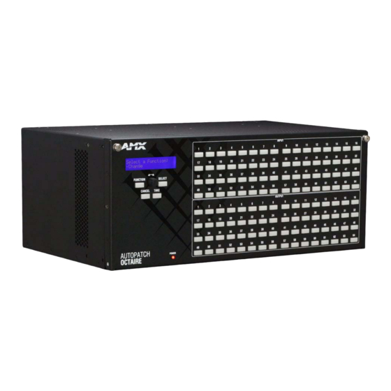
Page 16: Front View
The enclosure’s appearance, as viewed from the rear, will vary depending on the signal/connector types and the configuration size (which is also the main determinate of weight). Serial number FIG. 3 Rear view of 48x48 Octaire video enclosure Rear View Components Control hardware (CPU) Power receptacles with switches... -
Page 17: Serial Number
FIG. 5 Power supplies receptacles and switches The Octaire has dual power connections for the redundant power supplies located on the left. Each power supply has a power receptacle with a switch and will accept all major international standard power sources. -
Page 18: General Specifications
Thermal Dissipation (max.) Thermal Dissipation (typical) Humidity Enclosure Dimensions Weight Octaire Instruction Manual CE, UL, cUL 100 to 240 VAC single phase (50 to 60 Hz) 3.3 A @ 115 VAC max. 1.6 A @ 230 VAC max. 260 W per enclosure 120 W per enclosure, fully loaded 32°... -
Page 19: External Control Options
AMX AutoPatch CD or at www.amx.com. Third-Party Controllers A third-party controller can also be attached to an Octaire enclosure via the RS-232 serial port on the primary enclosure. If using a third-party controller, see the controller documentation for operating instructions. -
Page 20: Installation & Setup
113° (45° C) and follow the clearance recommendation below for adequate airflow. Airflow Restriction Octaire enclosures are designed to adequately dissipate the heat they produce under normal operating conditions; however, this design is defeated when high heat-producing equipment is placed directly above or below an enclosure. -
Page 21: Unpacking
27). After powering up the enclosure, apply power to the source and destination devices. Unpacking The Octaire is shipped with one enclosure per shipping box. The invoice is sent separately; a packing list is attached to the outside of each box. Each box contains the following items:... -
Page 22: Rack Installation & System Setup
Rack Installation & System Setup Octaire Distribution Matrix enclosures fit in a standard EIA 19 in. (48.26 cm) rack (rack ears are provided). Important: The system requires at least one empty rack unit above and below the enclosure to allow adequate airflow;... - Page 23 “Octaire AutoPatch Connector Guide” (page 96) are required for all video signals except composite. Do not apply power to the source and destination devices until after the Octaire has power (Step 7). Tip: Using lacer bars or some other type of cable management system lessens the strain from cable weight on the connectors and makes servicing the Octaire easier.
-
Page 24: Linking Enclosures
Caution: AMX AutoPatch systems can only be linked in their own isolated networks. Link Cable Requirements Octaire enclosures link directly to each other via the two LINK ports (RJ-45) at the lower right using the crossover cables that are provided. (Straight-through cable can also be used for linking. If straight- through cable is used, use it consistently between all enclosures in the system.) - Page 25 Insert the other end of the crossover cable into the upper LINK port on the second enclosure. For each additional enclosure in the system, attach crossover cables connecting from one enclosure’s LINK port to the next until all enclosures in the system are linked together according to the “Octaire AutoPatch Connector Guide” (page 96).
-
Page 26: Attaching Inputs & Outputs
Input and output connectors are the attachment points for source and destination devices that connect to the system. Viewed from the rear of an Octaire enclosure, the input connectors are in the center on the top with the output connectors directly below them. Input and output connectors are numbered separately. - Page 27 30). When the test switch is successful, attach the rest of the input and output cables (and wires). Tip: Using lacer bars or some other type of cable management system lessens the strain from cable weight on the connectors and makes servicing the Octaire easier. To connect video inputs and outputs: Fasten the cables onto the input and output BNC connectors (FIG.
- Page 28 Wiring Stereo Audio Connectors (5-position terminal block) The stereo audio connectors for the Octaire are pluggable 5-position terminal block. For stereo audio signal specifications, see the “Signal Types & Specifications” chapter (page 39). If full stereo is not required, mono audio can be used; wire either the left or right channel for all inputs and outputs.
-
Page 29: Attaching External Control
NetLinx master is connected to the RS-232 control port on the primary enclosure (the one with the control panel). APControl 3.0 APControl 3.0 software (for control and scheduling) runs on a PC connected to an Octaire via the serial port (DB-9) on the primary enclosure and is available on the AMX AutoPatch CD. APWeb (TCP/IP) The APWeb server (for control, diagnostics, and third-party access) is accessed through a TCP/IP interface such as a web browser (e.g., Internet Explorer). - Page 30 (null modem) serial cable attached to the serial port (DB-9) on the right rear of the primary enclosure. PCs are common serial controllers. Once a PC is attached to the Octaire, the system can be controlled by running APControl software on the attached PC (see the AMX AutoPatch CD). The system can also be controlled by entering BCS commands into a terminal emulation program (e.g., HyperTerminal).
- Page 31 Next; select Manual Configuration Entry/Next; enter Add VM information/Next; and finish the Wizard instructions. Terminal emulation settings to match the Octaire serial port settings (baud rate = 9600, data bits = 8, stop bit = 1, and parity and flow control = none). Click OK.
-
Page 32: Applying Power & Startup
Octaire, we recommend cabling the primary (upper) Octaire power feed(s) via a power strip to an outlet connected to one circuit breaker and the redundant (lower) power feed(s) via a power strip to an outlet connected to a second circuit breaker (see FIG. - Page 33 The system is ready for a test switch (see page 30, “Executing a Test Switch”). For startup information on specific types of control before executing a test switch, see page 30. Indicator Lights at Startup When the enclosure powers up, the indicator LEDs will respond as follows: Octaire LED Indicators Enclosure Power Front TCP/IP –...
- Page 34 [1:Enclosure] AMX AutoPatch Octaire Ready FIG. 22 Power-up splash screen in HyperTerminal Note: AMX reserves the right to add to the contents of the splash screen at any time, without notice. Octaire Instruction Manual Installation & Setup ® compatible and support Device Discovery.
-
Page 35: Executing A Test Switch
When using HyperTerminal, command characters are entered and sent to the primary enclosure’s CPU (the command characters appear in HyperTerminal when the enclosure responds). When all of the entered characters appear in HyperTerminal, the command has been successfully executed. compatible ® , contact your AMX representative. Octaire Instruction Manual... -
Page 36: Technical Support
Before contacting technical support with a question, please consult this manual. If you still have questions, contact your AMX representative or technical support. Have your system’s serial number ready. (The serial number label is located on the rear next to the power receptacles.) We recommend recording your system’s serial number in an easily accessible location. -
Page 37: Cabling & Setup For Vertical Interval Sync
Cabling & Setup for Vertical Interval Sync The Vertical Interval Sync (VIS) signal provides complete vertical interval synchronization switching capability for an Octaire system. The VIS function uses an external master sync signal, such as station master, blackburst, or composite video input. - Page 38 Note: If you need to provide a 75 ohm load for the external source, set the 75 ohm switch on the primary enclosure to “on” to provide the load. (When the 75 ohm switch is “off,” the input is terminated at high-impedance.) Octaire Instruction Manual Secondary Enclosure Secondary Enclosure...
- Page 39 Important: After the VIS toggle switches are set, the system must be enabled from the control panel to handle VIS switching. Enable the system for the VIS switching according to the directions in the “Setup Options” section on page 59. Octaire Instruction Manual...
-
Page 40: Connecting To The Apweb Server
AMX AutoPatch BCS (Basic Control Structure) commands. The primary enclosure (the one with the control panel) on the Octaire system is connected via a link (RJ-45) cable to a LAN (Local Area Network), the Internet, or a network card in a PC (which could then connect to a LAN or the Internet). - Page 41 The system setup example in FIG. 28 illustrates an Octaire Distribution Matrix connected to a LAN. Both computers in the illustration have access to the Octaire. If only one computer will be used, the Octaire’s APWeb (TCP/IP) port can be connected directly to the computer’s network card.
- Page 42 To connect the Octaire system to a LAN or to a PC: Complete the installation of the Octaire system (page 17); do not apply power until Step 4 below. Insert one end of the straight-through (RJ-45) cable into a network (NIC) card on a PC or an active LAN connection.
- Page 43 Installation & Setup Octaire Instruction Manual...
-
Page 44: Signal Types & Specifications
Signal Types & Specifications The Octaire Distribution Matrix is a fixed system, i.e., containing a single video type (with a single component per enclosure) or a single stereo audio enclosure or a single video type with stereo audio in a fixed input/output (I/O) range. - Page 45 75 ohms ±1.0 V 75 ohms 0 to +5 Volts 510 ohms +1.75 V Output polarity follows input polarity Active high or low 0 to +5 Volts 50 ohms Output polarity follows input polarity Active high or low Octaire Instruction Manual...
-
Page 46: Stereo Audio Signals
All Octaire systems with an audio enclosure route stereo audio signals. If full stereo is not required, the Octaire can be used for mono audio; wire either the left or right channel for all inputs and outputs. For information on wiring the connectors for balanced or unbalanced connections and on wiring sources and destinations, see “Attaching Inputs &... - Page 47 Signal Types & Specifications Octaire Instruction Manual...
-
Page 48: Octaire Control Panel Operation
Octaire Control Panel Operation Overview The Octaire Control Panel (standard on all systems) is used for controlling the system’s switches and system attributes. In multi-enclosure systems, the Control Panel is attached to the primary enclosure. Note: AMX AutoPatch software can also be used to control a system; for more information, see the AMX AutoPatch CD. - Page 49 Octaire Control Panel Operation Control Keys & Dial (continued) Take Key The Take Key functions much like the Enter Key on a computer keyboard. Pressing the Take Key instructs the system to execute or disconnect a switch. Prior to pressing the Take Key, the individual operation component(s) are selected by pressing the appropriate key(s).
- Page 50 Selecting the Virtual Matrix Mode accesses the three routing levels (virtual matrices) supported by the Octaire that route audio-follow-video signals (All), breakaway video signals (Video), and breakaway audio signals (Audio). While in the Virtual Matrix Mode, the virtual matrix / routing level needed to perform operations can be changed (see page 48).
- Page 51 Values for fields (such as routing levels, volume, or preset values): and Select Key. Executing a command: Labeling Input & Output Keys Each Octaire system ships with a custom labeling kit. Additional custom labeling kits may be ordered separately. The kit includes: Label holders Perforated card stock sheets The label template (an .xlt template formatted in Microsoft Excel) is included on the...
-
Page 52: Executing Switches
In an execute switch command either an input or an output can be selected first. To switch to multiple outputs, the Input Key must be selected first. With the Octaire Control Panel you can select and unselect Input and Output Keys to modify the switch as long as the keys are not flashing. Once satisfied with the switch selections, press the Take Key to execute it. - Page 53 Octaire Control Panel Operation Changing Virtual Matrices (Routing Levels) The Octaire system supports three routing levels (virtual matrices) for switching signals: All (Audio-follow-Video), Video, and Audio. Occasionally you may need to execute switches (or perform other operations) using a routing level other than the current one.
-
Page 54: Changing Virtual Matrices (Routing Levels)
Inputs and outputs can be selected in the same disconnect command. You can disconnect inputs or outputs from the Octaire Control Panel using the steps below. If you need to change the routing level, see “Changing Virtual Matrices (Routing Levels)” on page 48. -
Page 55: Verifying Signal Status
The status of inputs or outputs can be checked using the Octaire Control Panel. Once the Control Panel is in Status Mode, inputs and outputs can be selected by pressing the corresponding Input and Output Keys without changing the routing state. - Page 56 Defining & Executing Global Presets Global presets are predefined sets of switches that can easily be executed at one time. The Octaire Control Panel supports up to 64 global presets. A global preset number can be assigned to a routing state during runtime and stored by the system, allowing you to replicate an entire system state.
-
Page 57: Defining & Executing Global Presets
Octaire Control Panel Operation Scroll the Control Dial until Global Preset 3 appears. Press either the Select Key or the Take Key. Wait approximately ten seconds for the system to store the global preset setting. The current routing state can now be recalled as Global Preset 3, and the system returns to the Global Preset submenu. -
Page 58: Adjusting Audio
Audio adjustments are made with the Control Dial and do not require pressing the Take Key. You can adjust output volume, mute outputs, and adjust input gain from the Octaire Control Panel using the steps below and on the following pages. - Page 59 Octaire Control Panel Operation Press the Select Key again to choose Output Volume. The panel is in Output Volume Mode (all Input Keys are turned off, and the available Output Keys turn blue). Press the Output Key that corresponds to the output to be adjusted.
- Page 60 The Function menu appears. Locate Adjust Audio by scrolling with the Control Dial. Press the Select Key to enter the selection. The Adjust Audio submenu appears. Scroll the Control Dial to Input Gain. Octaire Instruction Manual Octaire Control Panel Operation Routing level...
- Page 61 Octaire Control Panel Operation Press the Select Key. The system is in Input Gain Mode (the available Input Keys turn blue, and all Output Keys are turned off). Press the Input Key that corresponds to the source that was routed in Step 1.
-
Page 62: Locking & Unlocking
Locking & Unlocking Locking the Octaire Control Panel prohibits access to the system and can prevent accidental switching. While the panel is locked, BCS commands still work; however, they cannot be used to unlock the panel. The panel remains locked if the power is cycled. - Page 63 Octaire Control Panel Operation Unlocking the Control Panel When the panel is locked and you press any key, the Unlock Panel Screen appears and you have ten (10) seconds to enter the password, or the Control Panel remains locked. If you wait longer than 10 seconds, press any key again before entering the password.
-
Page 64: Setup Options
– software version of the initial operating system (IOS) for the Control Panel XNet ID – Control Panel’s XNNet device number Use the following steps to check the software version information for the Octaire Control Panel. To check the software version information: Press the Function Key. -
Page 65: Setup Options
Or press the Function Key to return to the Function menu. Default Virtual Matrix The factory default virtual matrix (routing level) for the Octaire is All (Audio-follow-Video). You have the option of changing the factory default virtual matrix for your system. When you choose a new default virtual matrix, the system will revert to that virtual matrix each time the system is powered up even if you changed the virtual matrix using the V. - Page 66 If the enabling request is successful, the LCD returns to the Setup Options submenu. If the enabling request fails, the LCD will display an error message. For information on error codes, see page 64. Press the Function Key to return to the Function menu. Octaire Instruction Manual Octaire Control Panel Operation...
- Page 67 Setting the Password The Octaire’s default password is “1 2 3 4 5” entered using the first five input keys. A new password can be set using any combination of five of the Input Keys 1 through 8 when the LCD displays “Enter New PWD”...
- Page 68 Key to return to Enter New PWD screen and repeat Steps 5 through 7. When the new password is successfully reset, press the Cancel Key to return to the Setup Options submenu. Or press the Function Key to return to the Function menu. Octaire Instruction Manual Octaire Control Panel Operation...
- Page 69 System Error Codes & Troubleshooting This section provides an overview of the most common error codes that may appear on an Octaire Control Panel. The table below lists the error code, the name of the code, the meaning of the code, and some basic troubleshooting strategies (additional troubleshooting strategies are included on page 65).
-
Page 70: System Error Codes & Troubleshooting
Octaire Control Panel Operation Troubleshooting Error codes can appear either on the control panel’s LCD or in a terminal emulation program, such as HyperTerminal. When you are using a control panel, one of the most common troubleshooting strategies is to resend the command to see if the error was simply a timeout error. - Page 71 Octaire Control Panel Operation Octaire Instruction Manual...
-
Page 72: Apweb - Initial Setup By Network Admin
AMX AutoPatch BCS (Basic Control Structure) commands. The primary enclosure (the one with the control panel) on the Octaire system is connected via an RJ-45 link cable to a LAN (Local Area Network), the Internet, or a network card in a PC (which could then connect to a LAN or the Internet). -
Page 73: Opening The Apweb Server
A worksheet to record connection information is provided at the end of this chapter (see page 86). To set up the APWeb server: Follow the directions on page 35 for connecting the TCP/IP connector on the Octaire’s CPU to a LAN or to a network card in a PC. -
Page 74: Overview Of The Admin Home Page
BCS commands (page 81) Security information (page 71); it also includes the enable/disable services preferences (page 74) Displays the AMX address, phone and fax numbers, and website link APWeb – Initial Setup by Network Admin Customizable site name... -
Page 75: Setting A Static Ip Address
Important: Any time you select “Reboot” as an option from the APWeb Configuration page or from any dialog box opened from the APWeb site, the APWeb server reboots. The reboot updates information between the Octaire and the APWeb server. The Octaire system itself does not reboot. -
Page 76: Setting Admin & User Account Logins
Under Change User Account Login, enter none in both the Current Username and Current Password fields. Enter the new user name in the New Username field. Octaire Instruction Manual APWeb – Initial Setup by Network Admin User login information Administration login information... -
Page 77: Executing A Test Switch With The Xbar
Before executing the test switch, make sure the first source device and the first destination device are connected to the input and output connectors as indicated in the “Octaire AutoPatch Connector Guide.” (Depending on the signal and connector type, you may need to attach more than one input and output for a signal (e.g., a Y/c signal will be routed over a BNC connector on the enclosure that routes “Y”... -
Page 78: Executing A Test Switch With Bcs
Before executing the test switch, make sure the first source device and the first destination device are connected to the input and output connectors exactly as shown in the “Octaire AutoPatch Connector Guide” for your matrix switcher. Depending on the signal and connector type, you may need to attach more than one input and output for a signal (e.g., a Y/c signal will be routed over a BNC connector on... -
Page 79: Customizing The Site
Customizing the Site Name The site name for the APWeb server can be customized at the APWeb Configuration page. Customizing the site name can be especially useful when accessing multiple AMX AutoPatch Routing Systems from multiple APWeb servers on one PC. -
Page 80: Customizing Bootup Operations
Configuration page. Important: Any time you perform a reboot from the APWeb site, the APWeb server reboots. The reboot updates information between the AMX AutoPatch Routing System and the APWeb server. The AMX AutoPatch system itself does not reboot. To customize bootup operations: From any page in the site, click the Configuration link. -
Page 81: Customizing The Control Options
APWeb – Initial Setup by Network Admin Customizing the Control Options APWeb’s two options for controlling an AMX AutoPatch Routing System are the XBar Controller and custom macros (switches that execute simultaneously). Customizing the XBar The XBar displays the crosspoints for the input and output channels. The three options for customizing... - Page 82 The Octaire does not support local presets. Global presets are defined for the Octaire from its control panel (or by entering a BCS command in a terminal emulation program) and stored on the Octaire. An APWeb macro can consist of a command that executes a global preset command that was defined elsewhere (see the second example below).
-
Page 83: Defining Routing Levels (Manually Configuring Vms)
Click Delete. The macro is removed from the list on the Execute Macro page. Defining Routing Levels (Manually Configuring VMs) With the Octaire, routing level information can be manually entered to specify the routing levels, which are referred to as VMs (virtual matrices) in APWeb. With this feature you can provide selective control access to the system for different points of control. - Page 84 Home page, and to the list of VMs under the Delete VM section. Note: Deleting a VM that corresponds to one of the preconfigured levels on the Octaire will remove it from the APWeb server but not from the Octaire itself. To recover the preconfigured levels, turn VM discovery back on (reselect the Force VM Discovery option, see Steps 1 and 2 above).
-
Page 85: Handling Security Issues
APWeb server. When the Service switch is flipped to the right (FIG. 41), it is set for Service mode and the APWeb server is disabled. Caution: The steps on the following page will also automatically reset the default values for the IP Address and Subnet Mask. Octaire Instruction Manual... -
Page 86: Opening A Telnet Session
Enable/Disable Product Services options on the Administration page (see page 74). A Telnet session for controlling the Octaire with BCS commands can be opened by clicking the Launch Telnet Session button on the Diagnostics page. The button opens the PC’s default terminal emulation program (e.g., HyperTerminal on Windows). -
Page 87: Executing & Disconnecting Switches
(see page 85). Executing & Disconnecting Switches on the XBar The XBar Controller is a graphic interface control panel that executes switches on an AMX AutoPatch Routing System. The XBar can control specific parts of the system through routing levels, which are referred to as VMs (virtual matrices). -
Page 88: Adjusting Audio Settings
The most current routing state is displayed. Exit the VM Selection Pad when done. Adjusting Audio Settings If the Octaire system contains audio, both volume and input gain can be adjusted from the XBar controller after they are enabled (see page 76). Adjusting Volume The volume feature must be enabled. - Page 89 Check to be sure the VM is either VM 0 (All: audio-follow-video) or VM 2 (Audio). If not, you will need to change the routing level (see page 83). Route a source (input) to the desired destination (output) by clicking the desired I/O crosspoint. Octaire Instruction Manual...
-
Page 90: Executing Macros
When the text on the macro button turns green, the macro has successfully executed. (If the text on the macro button turns red, the macro failed to execute.) Octaire Instruction Manual APWeb – Initial Setup by Network Admin Macros are listed after being created... - Page 91 DNS (Domain Name Server) Server Addresses Primary DNS Server IP Address: ______ . ______ . ______ . ______ Secondary DNS Server IP Address: ______ . ______ . ______ . ______ TCP/IP BCS Tunnel: ___________ (default is 3600) ********************************************************** Octaire Instruction Manual...
-
Page 92: Apweb - Controlling The Octaire
APWeb – Controlling the Octaire This chapter starts with four easy steps for connecting to APWeb after the initial setup by the Network Administrator. It explains how to use APWeb’s two control options for executing and disconnecting switches: the XBar Controller (a crosspoint interface) and Macros (which are programmed by the Network Administrator). -
Page 93: Home Page
XBar. An APWeb server provides access to a single Octaire system from a specific IP address and can be accessed from up to five PCs at the same time. If you are controlling the same system as other users, you can open the VM Selection Pad and update status as needed (see page 91). - Page 94 Cursor over crosspoint Executing & Disconnecting Switches on the XBar Use the following directions to control the Octaire from the APWeb site. To execute or disconnect switches with the XBar: From any page in the site, click the Controller link.
- Page 95 APWeb – Controlling the Octaire Click a blue (inactive) crosspoint to execute a switch. The blue crosspoint image turns red as the switch is routed. Click a red (active) crosspoint to disconnect a switch. The red crosspoint image turns blue as the switch is disconnected.
-
Page 96: Executing Macros
Close the VM Selection Pad. Executing Macros A macro is a sequence of control commands that are executed simultaneously. Macros can be executed on the Octaire from the Execute Macro page. FIG. 44 Execute Macro page Note: If you need additional macros, contact your Network Administrator. -
Page 97: Apweb - Additional Info For Network Admin
<APPLET code="CrossBar.class" codebase="http://192.168.0.251" archive="CrossBar.jar" width=400 height=500 > <param name = "InitialVM" value = "0"> <param name = "VMLockDown" value = "locked"> <param name = "AllowGain" value = "true"> <param name = "AllowVolume" value = "true"> </APPLET> </BODY> </HTML> Octaire Instruction Manual... -
Page 98: Changing The Proxy Setting
If the Enter Network Password dialog box still does not open, you may need to add an exception in the Proxy Setting dialog box. To add an exception to the proxy setting information: From the Tools menu on the browser, select Internet Options. The Internet Options dialog box opens. Octaire Instruction Manual APWeb – Additional Info for Network Admin... - Page 99 The Local Area Network (LAN) Settings dialog box opens. If the Proxy server box is checked, go to Step 4. If the Proxy server box is not checked, check it before going to Step 4. Be sure Proxy server box is checked Octaire Instruction Manual...
- Page 100 In the Exceptions field, enter the appropriate APWeb IP address (the default is 192.168.0.251). Click OK to exit each of the dialog boxes used in these steps. Octaire Instruction Manual APWeb – Additional Info for Network Admin Enter APWeb IP address...
-
Page 101: Appendix A - Octaire Autopatch Connector Guide
Appendix A – Octaire AutoPatch Connector Guide Appendix A – Octaire AutoPatch Connector Guide Octaire Instruction Manual... -
Page 102: Appendix B - Programmer's Interface For System Diagnostics
Note: In a multi-enclosure system, the splash screen displays information only for the enclosure that is connected directly to the PC. * AMX reserves the right to add to the contents of the splash screen at any time, without notice. Octaire Instruction Manual Appendix B –... - Page 103 System Sensors Tip: The information in the above table is displayed when you enter ~scr! or ~scri0v1! General Rules for Octaire Diagnostic Commands In a multi-enclosure system, the splash screen displays information only for the enclosure that is connected directly to the PC If the verbosity setting is omitted, the verbosity level will be the lowest (v0) The component setting must be included;...
- Page 104 [type] BCS mode RS232 port, 9600 (8/1/N/E/NS) [interface 2] detected [type] BCS mode RS232 port, 115200 (8/1/N/NE/NS) [interface 3] detected [type] MCF5282 FEC Ethernet Controller FIG. 48 Display for i3v3 (component 3, verbosity 3) Octaire Instruction Manual Appendix B – Programmer’s Interface for System Diagnostics...
- Page 105 Appendix B – Programmer’s Interface for System Diagnostics Octaire Instruction Manual...
- Page 106 It’s Your World - Take Control™ 3000 RESEARCH DRIVE, RICHARDSON, TX 75082 USA • 800.222.0193 • 469.624.8000 • 469-624-7153 fax • 800.932.6993 technical support • www.amx.com...