Table of Contents

Related Manuals for York YD A


Summary of Contents for York YD A
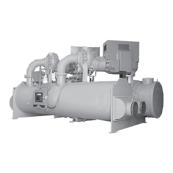
- Page 1 CENTRIFUGAL LIQUID CHILLERS OPERATING & MAINTENANCE Supersedes: 160.69-O2 (912) Form 160.69-O2 (920) MODEL YD (STYLE A & B) WITH OPTIVIEW™ CONTROL CENTER AND ELECTRO-MECHANICAL STARTER COOLING ONLY LD08634 R-134A Issue Date: September 30, 2020...
- Page 2 FORM 160.69-O2 ISSUE DATE: 9/30/2020 IMPORTANT! READ BEFORE PROCEEDING! GENERAL SAFETY GUIDELINES This equipment is a relatively complicated apparatus. which it is situated, as well as severe personal injury or During installation, operation maintenance or service, death to themselves and people at the site. individuals may be exposed to certain components or This document is intended for use by owner-authorized conditions including, but not limited to: refrigerants,...
- Page 3 Planned Service Agreement that leverages real time and generalized conditions. In lieu of the traditional and historical data, delivering performance reporting, maintenance program, a Johnson Controls YORK corrective actions required and data enabled guidance Conditioned Based Maintenance (CBM) program can for optimal operation and lifecycle assurance.
- Page 4 FORM 160.69-O2 ISSUE DATE: 9/30/2020 NOMENCLATURE – A, B, or C DESIGN LEVEL MOTOR CODE 60 Hz 50 Hz POWER SUPPLY - for 60 Hz 5 for 50 Hz COMPRESSOR CODE J1, J2, J3, J4, J5 CONDENSER CODE XA, XB, XC, XD, YA, YB, YC, YD, ZA, ZB, ZC, ZD, AA, AB, AC, AD EVAPORATOR...
-
Page 5: Table Of Contents
FORM 160.69-O2 ISSUE DATE: 9/30/2020 TABLE OF CONTENTS SECTION 1 – DESCRIPTION OF SYSTEM AND FUNDAMENTALS OF OPERATION ........9 System Operation Description .......................... 9 Compressor Starting ............................10 Compressor Shutdown ........................... 14 SECTION 2 – SYSTEM OPERATING PROCEDURES ..................23 Oil Heaters .............................. - Page 6 FORM 160.69-O2 ISSUE DATE: 9/30/2020 TABLE OF CONTENTS (CONT'D) Megging The Motor ............................43 Condensers And Evaporators .......................... 45 General ................................45 Chemical Water Treatment ..........................45 Cleaning Evaporator And Condenser Tubes ....................45 Tube Fouling ..............................45 Tube Cleaning Procedures ..........................45 Acid Cleaning Of Tubes ..........................
- Page 7 FORM 160.69-O2 ISSUE DATE: 9/30/2020 LIST OF FIGURES FIGURE 1 - Model YD Chiller ...........................9 FIGURE 2 - Chiller Operation Flow Chart .......................15 FIGURE 3 - Oil Level Indicator ..........................23 FIGURE 4 - Liquid Chiller Log Sheets ........................25 FIGURE 5 - System Components ...........................30 FIGURE 6 - Schematic Drawing –...
- Page 8 FORM 160.69-O2 ISSUE DATE: 9/30/2020 THIS PAGE INTENTIONALLY LEFT BLANK. JOHNSON CONTROLS...
-
Page 9: Section 1 - Description Of System And Fundamentals Of Operation
FORM 160.69-O2 ISSUE DATE: 9/30/2020 SECTION 1 – DESCRIPTION OF SYSTEM AND FUNDAMENTALS OF OPERATION SYSTEM OPERATION DESCRIPTION The following is a high level description of the chill- Each compressor also has a Discharge Temperature er control. It describes the overall operation. Control thermistor and High Pressure safety device. -
Page 10: Compressor Starting
FORM 160.69-O2 SECTION 1 – DESCRIPTION OF SYSTEM AND FUNDAMENTALS OF OPERATION ISSUE DATE: 9/30/2020 The Chiller Current Limit setpoints are used to spec- If equipped with the compressor Variable Geometry ify the motor current limit for the chiller as a whole. Diffuser (VGD), the chiller is started with the VGD in There are two setpoints: the Chiller Pulldown Demand the fully open position. - Page 11 FORM 160.69-O2 SECTION 1 – DESCRIPTION OF SYSTEM AND FUNDAMENTALS OF OPERATION ISSUE DATE: 9/30/2020 Level Control Setpoint. This ramp allows the level to run time of the compressors are evaluated to deter- go from the present level to the Level Control Setpoint mine which should be the Lead compressor (The one over a period programmed as the Ramp Up Time with the least amount of run time is identified as the...
- Page 12 FORM 160.69-O2 SECTION 1 – DESCRIPTION OF SYSTEM AND FUNDAMENTALS OF OPERATION ISSUE DATE: 9/30/2020 An LED on the Surge – Dual Compressor Setup Screen the time remaining in the “Valve Preset” mode or the and the Capacity Compressor Cycling Screen illumi- time remaining in the “Lag Start”...
- Page 13 FORM 160.69-O2 SECTION 1 – DESCRIPTION OF SYSTEM AND FUNDAMENTALS OF OPERATION ISSUE DATE: 9/30/2020 brought on line. After this period has elapsed, the lag With Software version C.OPT.11.03.01.004 (or later), compressor can be brought on line per normal opera- a single compressor can be locked out while both com- tion.
-
Page 14: Compressor Shutdown
FORM 160.69-O2 SECTION 1 – DESCRIPTION OF SYSTEM AND FUNDAMENTALS OF OPERATION ISSUE DATE: 9/30/2020 Normal or Single Compressor Mode (Software version C.OPT.11.03.01.004 (or later)) pressor enters “Coastdown”. If any Discharge Valve does not close within 40 seconds, a cycling shutdown The COMPRESSOR MODE Setpoint, available on the is performed and “Discharge #X –... -
Page 15: Figure 2 - Chiller Operation Flow Chart
FORM 160.69-O2 SECTION 1 – DESCRIPTION OF SYSTEM AND FUNDAMENTALS OF OPERATION ISSUE DATE: 9/30/2020 YD Dual Compressor Chiller Chiller Standby Electro-Mechanical Starter Chiller Start Sequence Compressor Start Inhibit Disch Valves Closed? Chiller Start Requirement Is a Compressor in Select Lead Compressor Service Lockout Select the other Select the Compressor... - Page 16 FORM 160.69-O2 SECTION 1 – DESCRIPTION OF SYSTEM AND FUNDAMENTALS OF OPERATION ISSUE DATE: 9/30/2020 YD Dual Compressor Chiller Electro-Mechanical Starter Chiller Start Sequence 1 compressor running (from Page 1) Is La Compressor in Don't start lag compressor Service Lockout Single Compressor Mode? Lead...
- Page 17 FORM 160.69-O2 SECTION 1 – DESCRIPTION OF SYSTEM AND FUNDAMENTALS OF OPERATION ISSUE DATE: 9/30/2020 YD Dual Compressor Chiller Normal Safety Checks Electro-Mechanical Starter (Except for oil low temp Chiller Start Sequence differential) Lag Compr Startup PRVs and Start Lag Compressor From Disch Valve on Motor...
- Page 18 FORM 160.69-O2 SECTION 1 – DESCRIPTION OF SYSTEM AND FUNDAMENTALS OF OPERATION ISSUE DATE: 9/30/2020 YD Dual Compressor Chiller Electro Mechanical Chiller 2 Compressors Running Capacity Cycling (Lag Compressor Stop) Sequence (from Page 3) Has Lag Compressor Run >30 Min As motor currents fall below 50% with Motor Current two compressors running, a single...
- Page 19 FORM 160.69-O2 SECTION 1 – DESCRIPTION OF SYSTEM AND FUNDAMENTALS OF OPERATION ISSUE DATE: 9/30/2020 YD Dual Compressor Chiller Electro Mechanical Starter Chiller Soft Shutdown 2 Compressors Running 1 Compressor Running (from Page 3) (from Page 1 or 4) Chiller normal Chiller normal or cycling stop or cycling stop...
- Page 20 FORM 160.69-O2 SECTION 1 – DESCRIPTION OF SYSTEM AND FUNDAMENTALS OF OPERATION ISSUE DATE: 9/30/2020 YD Dual Compressor Chiller Electro-Mechanical Starter Chiller Fault Stop (manual or auto restart) 2 Compressors Running 1 Compressor Running (from Page 3) (from Page 1 or 4) Chiller Fault Chiller Fault Condition...
- Page 21 FORM 160.69-O2 SECTION 1 – DESCRIPTION OF SYSTEM AND FUNDAMENTALS OF OPERATION ISSUE DATE: 9/30/2020 YD Dual Compressor Chiller Anti-Surge Control Algorithm Chiller Running Two Compressor Mode. Lead Compressor controlling LChWT Lag Compressor following current of Lead Are Compressor Motor Currents Equal within 20% Are vanes on the lower current compressor open more than the...
- Page 22 FORM 160.69-O2 ISSUE DATE: 9/30/2020 THIS PAGE INTENTIONALLY LEFT BLANK. JOHNSON CONTROLS...
-
Page 23: Section 2 - System Operating Procedures
FORM 160.69-O2 ISSUE DATE: 9/30/2020 SECTION 2 – SYSTEM OPERATING PROCEDURES OIL HEATERS START-UP PROCEDURE If the oil heater is de-energized during a shutdown pe- Pre-Starting riod, it must be energized for 12 hours prior to starting Prior to starting the chiller, observe the OptiView™ compressor, or remove all oil and recharge compressor Control Center. -
Page 24: Start-Up
FORM 160.69-O2 SECTION 2 – SYSTEM OPERATING PROCEDURES ISSUE DATE: 9/30/2020 START-UP 1. If the chilled water pump is manually operated, 4. The chilled liquid pump contacts will close, start- start the pump. The Control Center will not al- ing the chilled liquid pump, to allow liquid flow low the chiller to start unless chilled liquid flow through the evaporator when the COMPRESSOR is established through the unit. -
Page 25: Condenser Water Temperature Control
CONDENSER WATER TEMPERATURE CONTROL entering condenser water temperature on most instal- lations. The YORK YD chiller is designed to use less power by taking advantage of lower than design temperatures OPERATING LOG SHEET that are naturally produced by cooling towers through- A permanent daily record of system operating condi- out the operating year. -
Page 26: Operating Inspections
FORM 160.69-O2 SECTION 2 – SYSTEM OPERATING PROCEDURES ISSUE DATE: 9/30/2020 OPERATING INSPECTIONS Monthly Leak check the entire chiller. By following a regular inspection using the display readings of the Microcomputer Control Center, and Quarterly maintenance procedure, the operator will avoid serious operating difficulty. -
Page 27: Need For Maintenance Or Service
YORK District Office. Failure to report con- system to stand for a long period of time. stant troubles could damage the unit and increase the cost of repairs. - Page 28 FORM 160.69-O2 ISSUE DATE: 9/30/2020 THIS PAGE INTENTIONALLY LEFT BLANK. JOHNSON CONTROLS...
-
Page 29: Section 3 - System Components Description
ISSUE DATE: 9/30/2020 SECTION 3 – SYSTEM COMPONENTS DESCRIPTION 1. Compressor Drive Shaft (Low Speed) GENERAL The YORK Model YD Centrifugal Liquid Chiller is a. Shaft seal. completely factory-packaged including evaporator, b. Front and rear journal bearings – one on... -
Page 30: Oil Pump
FORM 160.69-O2 SECTION 3 – SYSTEM COMPONENTS DESCRIPTION ISSUE DATE: 9/30/2020 OIL PUMP For normal operation, the oil pump should operate at all times during chiller operation. On shutdown of the system for any reason, the oil pump operates and continues to run for 150 seconds. The system cannot restart during that time interval. -
Page 31: Figure 6 - Schematic Drawing - (Yd) Compressor Lubrication System
FORM 160.69-O2 SECTION 3 – SYSTEM COMPONENTS DESCRIPTION ISSUE DATE: 9/30/2020 DOUBLE BELLOWS SHAFT SEAL LOW SPEED GEAR REAR BEARING LD08577 FIGURE 6 - SCHEMATIC DRAWING – (YD) COMPRESSOR LUBRICATION SYSTEM JOHNSON CONTROLS... -
Page 32: Oil Heater
Victaulic grooves are welded to the water boxes. These The compressor motor is an open-drip-proof, squir- nozzle connections are suitable for Victaulic couplings, rel cage, induction type constructed to YORK design welding or flanges, and are capped for shipment. specifications. 60 hertz motors operate at 3570 rpm. 50 Plugged 3/4"... -
Page 33: Optional Hot Gas Bypass
FORM 160.69-O2 SECTION 3 – SYSTEM COMPONENTS DESCRIPTION ISSUE DATE: 9/30/2020 While the chiller is running, the refrigerant level is nor- OPTIONAL HOT GAS BYPASS mally controlled to the level setpoint. However, anytime Hot gas bypass is optional and is used to eliminate the vanes fully close (VMS closes), normal level control compressor surge during light load or high head op- is terminated, any refrigerant level setpoint pulldown in... - Page 34 FORM 160.69-O2 ISSUE DATE: 9/30/2020 THIS PAGE INTENTIONALLY LEFT BLANK. JOHNSON CONTROLS...
-
Page 35: Section 4 - Operational Maintenance
FORM 160.69-O2 ISSUE DATE: 9/30/2020 SECTION 4 – OPERATIONAL MAINTENANCE OIL RETURN SYSTEM CHANGING THE DEHYDRATOR The oil return system continuously maintains the prop- To change the dehydrator, use the following procedure: er oil level in the compressor oil sump. 1. -
Page 36: The Oil Charge
The nominal oil charge for all YD chillers is 45 gal- plate. (See Figure 8 on page 36) Do not tighten lons of type “York K”. If operating at ambient temps > the connection at the charging valve until after the 104˚F, use "YORK H"... -
Page 37: Section 5 - Troubleshooting
FORM 160.69-O2 ISSUE DATE: 9/30/2020 SECTION 5 – TROUBLESHOOTING TABLE 1 - OPERATION ANALYSIS CHART RESULTS POSSIBLE CAUSE REMEDY SYMPTOM: ABNORMALLY HIGH DISCHARGE PRESSURE Temperature difference between condensing temperature and water off Air in condenser condenser Clean condenser tubes. Check water Condenser tubes dirty or scaled conditioning. - Page 38 FORM 160.69-O2 SECTION 5 – TROUBLESHOOTING ISSUE DATE: 9/30/2020 TABLE 1 – OPERATION ANALYSIS CHART (CONT'D) RESULTS POSSIBLE CAUSE REMEDY SYMPTOM: OIL PUMP VIBRATES OR IS NOISY Oil pump vibrates or is extremely noisy with some oil pressure when pressing Oil not reaching pump suction inlet in Check oil level.
-
Page 39: Section 6 - Maintenance
FORM 160.69-O2 ISSUE DATE: 9/30/2020 SECTION 6 – MAINTENANCE CHECKING SYSTEM FOR LEAKS To test with R-22, proceed as follows: 1. With no pressure in the system, charge R-22 gas Leak Testing During Operation into the system through the charging valve to a The refrigerant side of the system is carefully pressure pressure of 2 PSIG (14 kPa). -
Page 40: Vacuum Testing
FORM 160.69-O2 SECTION 6 – MAINTENANCE ISSUE DATE: 9/30/2020 TABLE 2 - SYSTEM PRESSURES * GAUGE ABSOLUTE BOILING Inches Of Mercury TEMPERATURES OF Millimeters Of (HG) Below One PSIA Microns WATER °F Mercury (HG) Standard Atmosphere 14.696 760. 760,000 10.24" 9.629 500. -
Page 41: Vacuum Dehydration
FORM 160.69-O2 SECTION 6 – MAINTENANCE ISSUE DATE: 9/30/2020 When this point is reached, practically all of the air has VACUUM DEHYDRATION been evacuated from the system, but there is still a small To obtain a sufficiently dry system, the following in- amount of moisture left. -
Page 42: Refrigerant Charging
FORM 160.69-O2 SECTION 6 – MAINTENANCE ISSUE DATE: 9/30/2020 REFRIGERANT CHARGING While charging, every precaution must be taken to pre- To avoid the possibility of freezing liquid within the vent moisture laden air from entering the system. evaporator tubes when charging an evacuated system, only refrigerant vapor from the top of the cylinder The charging connection should be purged each time must be admitted to the system pressure until the sys-... -
Page 43: Checking The Refrigerant Charge During Unit Shutdown
FORM 160.69-O2 SECTION 6 – MAINTENANCE ISSUE DATE: 9/30/2020 CHECKING THE REFRIGERANT CHARGE HANDLING REFRIGERANT FOR DURING UNIT SHUTDOWN DISMANTLING AND REPAIRS The refrigerant charge is specified for each chiller If it becomes necessary to open any part of the refriger- model (See Table 3 on page 42). -
Page 44: Figure 12 - Motor Starter Temperature And Insulation Resistances
FORM 160.69-O2 SECTION 6 – MAINTENANCE ISSUE DATE: 9/30/2020 LD00476 TEMPERATURE – °f FIGURE 12 - MOTOR STARTER TEMPERATURE AND INSULATION RESISTANCES JOHNSON CONTROLS... -
Page 45: Condensers And Evaporators
FORM 160.69-O2 SECTION 6 – MAINTENANCE ISSUE DATE: 9/30/2020 CONDENSERS AND EVAPORATORS Condenser In a condenser, trouble due to fouled tubes is usually GENERAL indicated by a steady rise in head pressure, over a pe- Maintenance of condenser and evaporator shells is im- riod of time, accompanied by a steady rise in condens- portant to provide trouble free operation of the chiller. -
Page 46: Acid Cleaning Of Tubes
If acid cleaning is required, YORK tube, indicating the location of the leakage. If not, recommends the use of this type of organization. The... -
Page 47: Compressor
YORK office to request the presence of a Internal wearing of compressor parts could be a seri- YORK Service Technician. - Page 48 FORM 160.69-O2 ISSUE DATE: 9/30/2020 THIS PAGE INTENTIONALLY LEFT BLANK. JOHNSON CONTROLS...
-
Page 49: Section 7 - Preventive Maintenance
(See Table 4 on page 49) ranty period; YORK will not be liable for costs in- curred to return the system to satisfactory operation. TABLE 4 - BEARING LUBRICATION... -
Page 50: Leak Testing
2. It is important that the factory settings of controls (operation and safety) not be changed. If the set- tings are changed without YORK’s approval, the warranty will be jeopardized. JOHNSON CONTROLS... -
Page 51: Metric Conversion
FORM 160.69-O2 ISSUE DATE: 9/30/2020 The following factors can be used to convert from English to the most common SI Metric values. TABLE 5 - SI METRIC CONVERSION MEASUREMENT MULTIPLY ENGLISH UNIT BY FACTOR TO OBTAIN METRIC UNIT Capacity Tons Refrigerant Effect (ton) 3.516 Kilowatts (kW) Power... - Page 52 5000 Renaissance Drive, New Freedom, Pennsylvania USA 17349 1-800-524-1330 Subject to change without notice. Printed in USA Copyright © by Johnson Controls 2020 www.johnsoncontrols.com ALL RIGHTS RESERVED Form 160.69-O2 (920) Issue Date: September 30, 2020 Supersedes: 160.69-O2 (912)