Table of Contents
Advertisement
Quick Links
RASI Series
SpeedDome Optima Indoor Installation Guide
Before performing these steps, ensure power is off and
read additional information attached for important
details and warnings!
1
2
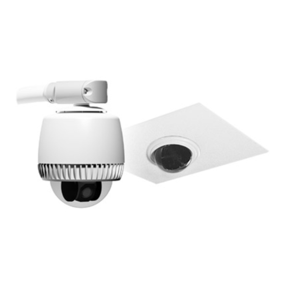
Using the template
supplied, c ut a hole in
the ceiling.
3
Adjust all four "swing
out" mounting clips for
the ceiling thickness..
A
T he address range is from 001 to 255,
except for Manc hester, which is 01 to 64.
S et switches. Example: For address 107,
set S W3 to 1, S W2 to • , and S W1 to 7.
B
T he camera/motor assembly is shipped
"terminated" (switch to left) for when it is installed
at the end of a data cable. S hould the cable
continue to another dome, move the slide
switch to the right to "unterminate".
S et the dome address and
terminate the dome, if
necessary.
T erminate
S witc h
T
x100
x10
x1
7
SW3
SW2
SW1
Address S witches
4
Cable
hookup
SensorNet
RS422
Manchester
Output
Input
1
1
1
Power
Alarm
Data
Video
(Green)
(Grey)
(Black)
C
Place cover
on housing.
D
S ecure cable to
housing using the
cable tie supplied.
P age 1 of 18
B
Attach cable connectors.
Ensure power is off.
Use screwdriver
supplied to tighten
connec tor screws. DO
NOT over tighten the
connec tors!
A
If running cables through
conduit (not shown), remove
appropriate knockout (1/2in
Or 3/4in), and connect
conduit to the cover.
If running cables direct
(shown), attach the clamp
and nut assembly supplied to
one of the 1/2in knockouts in
the side of the cover.
8000-2692-01, R ev. E
Advertisement
Table of Contents

Related Manuals for American Dynamics RASIPPS-1


Summary of Contents for American Dynamics RASIPPS-1
- Page 1 RASI Series SpeedDome Optima Indoor Installation Guide Before performing these steps, ensure power is off and read additional information attached for important details and warnings! Using the template Adjust all four “swing supplied, c ut a hole in out” mounting clips for the ceiling.
- Page 2 S ecure the housing to a strong structural ceiling member. Run the chain up into the ceiling and wrap it around a structural member above the housing. Keep the chain taught as possible. Do not sec ure the housing to Attach the end of the a fire c ontrol system.
- Page 3 RASO Series SpeedDome Optima Outdoor Installation Guide = Step Prevents Water Intrusion. At end of pipe. S eal Ensure black foam plug is around Ensure seal and sleeve cable and press-fit into pipe. are properly set. S ee A, B , C. Line up.
- Page 4 S et the dome address and terminate the dome, if necessary. R emove the c amera/motor assembly from the housing. Loosen three c aptive sc rews and push in all three tabs simultaneously to release the assembly from the housing. T he address range is from 001 to 255, except for Manc hester, which is 01 to 64.
-
Page 5: Table Of Contents
SpeedDome Optima ® Housing Continuation of Installation Information RASI Indoor Series RASO Outdoor Series Contents To the Installer... 5 Special Product Features ... 5 Tools Required ... 5 Warnings and Cautions ... 6 Preventing Condensation in Outdoor Domes... 7 Connector Pin Assignments ... 7 Cable Requirements... -
Page 6: Warnings And Cautions
Warnings and Cautions Please review the following warnings and cautions before you begin installation or service. Warnings WARNING! Always use proper lift and safety equipment for the location and type of installation. Use the safety features of the lift equipment. WARNING! When connecting wires, ensure electrical power is not connected... -
Page 7: Preventing Condensation In Outdoor Domes
Preventing Condensation in Outdoor Domes Damage, missing parts, or procedures that most often allow water to enter the housing are as follows (refer to figures opposite): Mounts that allow water to enter the air path. If an older horizontal mount is used, replace it with a new model or ensure there is ample slope away from the camera dome and a foam plug is present... -
Page 8: Cable Requirements
Cable Requirements Data Cable The table below shows requirements for SensorNet, RS-422, and Manchester networks. For more information about communication protocols and cable networks, see Communication Protocols and Cable Networks, 8000-2573-19. Data cable requirements SensorNet RS-422 Cable type unshielded, shielded, twisted twisted pair*... -
Page 9: Synchronizing Domes
Indoor Dome Worst-Case AC Power Source Low Line V 28 VA Transformer 5604-0006-01 50 VA Transformer 5604-0044-01 1-position SensorNet or RS 422 J-Box RJ1SNUD, RS856UD 1-position SensorNet or RS 422 J-Box RJ1SNUD-1, RS856UD-1 6-position SensorNet Indoor J-Box RJ6SN 10-position RS 422 Indoor 120V/60Hz J-Box RJ860AP 10-position RS 422... -
Page 10: Troubleshooting
Troubleshooting If a failure cannot be easily fixed external to the dome, send the dome to a repair center. No power (no LEDs light). Check for power coming in from J-box or controller. Homing routine does not complete. Green, red, and yellow LEDs are visible through small holes in the dome housing that surround the camera yoke. -
Page 11: Illustrated Parts List
Illustrated Parts List Not all of the parts, which are shown for clarity, are orderable. Parts are subject to change based on design improvements and availability. Indoor Housing SPEEDDOME OPTIMA HOUSING CONTINUATION OF INSTALLATION GUIDE Hard Ceiling Housing Assy. 0400-1246-01 Housing, Assembly Cable Assy., Pigtail 11 of 18... - Page 12 Outdoor Housing Indoor/Outdoor Housing Assy. 0400-1208-01 Housing, Aluminum Sun Shield Top Cover Mounting Support Nut, Locking, M6, SS (4) Washer, FL, STD, M6 (4) Gasket Lock Nut, 1-1/2 Screw, M6x40 HHD Indoor/Outdoor, Pigtail Only 0400-1221-01 Bracket, Mounting Cable Assy., Pigtail SPEEDDOME OPTIMA HOUSING CONTINUATION OF INSTALLATION GUIDE 0500-9175-01...
- Page 13 Camera/Motor Assembly Tilt Assy. 0400-1207-01/-02 Base Assy. 0400-1203-01 SPEEDDOME OPTIMA HOUSING CONTINUATION OF INSTALLATION GUIDE 13 of 18 8000-2692-01, REV. E...
- Page 14 Base Assy. 0400-1203-01 Bearing, Pan Pan Motor Assy. PCB, Dome System Tilt Assy. 0400-1207-01 (NTSC), -02 (PAL) Base, Tilt Spacer, Tilt (2) Tilt Upright (2) Timing Belt Tilt Motor with Pulley PCB, Tilt Sensor SPEEDDOME OPTIMA HOUSING CONTINUATION OF INSTALLATION GUIDE 2510-0040-01 0400-1240-01 0301-1516-01...
-
Page 15: Specifications
Specifications Operation Manual pan speed ... 1–50° per second Target pan speed ... 100° per second max. Pan travel ... 360° continuous, no end stop Manual tilt speed ... 1–50° per second. Target tilt speed... 50° per second max. Tilt travel ... >90° Optical zoom... - Page 16 Electrical Power Line Input voltage ...24–30Vac, Class 2 LPS Design tolerance...16–36Vac Line frequency ...50/60Hz Power consumption ...15W max. Power on inrush current...3A Allowable drop out: ...33ms Connector: ...Plug-in Euro-style terminal block 5.08mm Max. cable distance ...250m from Junction Box using composite cable Surge Protection Video output ...
- Page 17 Manchester Communications Cable topology... Daisy chain Wire configuration... Single twisted pair 18AWG (Belden 8760), polarized, shielded Connector ... Plug-in Euro-style terminal block 3.81mm Terminating resistor ... 120 ohms, switch selectable Alarm Input Provides signal input to dome alarm. Connector ... Plug-in Euro-style terminal block 3.81mm Relay Output Provides contact closure output from dome output.
-
Page 18: Declarations
SPEEDDOME OPTIMA HOUSING CONTINUATION OF INSTALLATION GUIDE Other Declarations Thank you for using American Dynamics products. We support our products through an extensive and worldwide network of dealers. The dealer, through whom you originally purchased this product, is your point of contact if you have a need for service or support.