Emerson Bettis SCE300 Installation, Operation And Maintenance Manual
Hide thumbs
Also See for Bettis SCE300:
- Installation, operation and maintenance manual (22 pages) ,
- Installation, operation and maintenance manual (22 pages)

Related Manuals for Emerson Bettis SCE300


Summary of Contents for Emerson Bettis SCE300
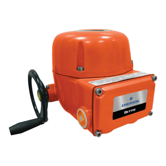
- Page 1 Installation, Operation and Maintenance Manual MAN-02-04-99-0712-EN Rev. 1 February 2020 Bettis SCE300 Electric Actuator...
-
Page 3: Table Of Contents
Installation, Operation and Maintenance Manual Table of Contents MAN-02-04-99-0712-EN Rev. 1 February 2020 Table of Contents Section 1: General Safety Instructions Intended Use ....................1 Terms and Conditions ................... 2 Manufacturer's Liability ................. 2 Identification ....................3 1.4.1 Water - Dust-Proof Version ..............3 1.4.2 Explosion-Proof Version .............. - Page 4 Table of Contents Installation, Operation and Maintenance Manual February 2020 MAN-02-04-99-0712-EN Rev. 1 Section 5: Lubrication Lubrication Inspection................. 28 Section 6: Actuator Configuration Removal of the Control Unit Cover .............. 29 Local Configuration of the SCE300 .............. 30 6.2.1 SCE300 Default General Configuration ..........30 6.2.2 Close Limit Configuration by Position ..........
-
Page 5: Section 1: General Safety Instructions
Inform Emerson as a matter of urgency if you face unsafe situations not described in this IOM. It is the sole responsibility of the operator to ensure that local health and safety regulations are adhered to. -
Page 6: Terms And Conditions
MAN-02-04-99-0712-EN Rev. 1 Terms and Conditions Emerson guarantees every product to be free from defects and to conform to current goods specifications. The warranty period is one year from the date of installation by the first user or eighteen months from the date of shipment to the first user, whichever occurs first. -
Page 7: Identification
Section 1: General Safety Instructions Installation and Maintenance Instructions MAN-02-04-99-0712-EN Rev. 1 February 2020 Identification 1.4.1 Water - Dust-Proof Version The SCE300 actuator is designed and manufactured according to EN 60529 standards. Specific types of protection are printed on the label as follows: •... -
Page 8: Explosion-Proof Version
Section 1: General Safety Instructions Installation and Maintenance Instructions February 2020 MAN-02-04-99-0712-EN Rev. 1 1.4.2 Explosion-Proof Version The version of the SCE300 suitable for installation in hazardous areas is designed and manufactured according to EN 60079-0, EN 60079-1, EN IEC 60079-7, EN 60079-3 standards. Different types of protection are available, depending on the requirements of the installation site. - Page 9 Section 1: General Safety Instructions Installation and Maintenance Instructions MAN-02-04-99-0712-EN Rev. 1 February 2020 Figure 2 Atex Label For Application In Hazardous Areas A. Manufacturer logo B. Product model C. Nominal output torque value D. Product code E. Serial number F.
-
Page 10: Applicable Standards And Regulations
Section 1: General Safety Instructions Installation and Maintenance Instructions February 2020 MAN-02-04-99-0712-EN Rev. 1 Applicable Standards and Regulations EN ISO 12100-1 Safety of machinery Basic concepts, general principles for design Part 1 Basic terminology, methodology EN ISO12100-2 Safety of machinery Basic concepts , general principles for design Part 2 Technical principles and specification EN 60204-1... -
Page 11: Section 2: Machine Description
Section 2: Machine Description Installation and Maintenance Instructions MAN-02-04-99-0712-EN Rev. 1 February 2020 Section 2: Machine Description General The SCE300 is an electric quarter-turn actuator suitable for operating a valve in a 90° stroke. Principle of Operation The electric motor drives the input to an epicyclical gear train via a spur reduction. The input member of the epicyclical gear train carries two compound planet gears which meshes with one internally toothed gear: the fixed annulus. -
Page 12: Manual Operation
Section 2: Machine Description Installation and Maintenance Instructions February 2020 MAN-02-04-99-0712-EN Rev. 1 Manual Operation Manual operation is to be used in cases of power supply failure or during actuator configuration. The manual operating device is completely independent of the motor drive and can be operated at any time - whether or not the motor is running - without danger to the operator. -
Page 13: Optional Modules
Section 2: Machine Description Installation and Maintenance Instructions MAN-02-04-99-0712-EN Rev. 1 February 2020 Optional Modules SCE300 actuators can be provided with several optional modules, as listed in the table below. Refer to this table for possible combinations of available modules. Table 2. -
Page 14: Options Label
Section 2: Machine Description Installation and Maintenance Instructions February 2020 MAN-02-04-99-0712-EN Rev. 1 Options Label A label depicting all possible options is always provided with the base SCE300 actuator. If a module(s) is installed after the actuator has been delivered, the local operator must mark the label to show that the relevant module(s) were installed. -
Page 15: Section 3: Storage And Pre-Installation
The standard plastic plugs used to close the cable entries are not weather-proof; these plugs are only intended to prevent the entry of foreign objects during transport. Emerson cannot accept responsibility for deterioration caused on-site when the covers are removed. -
Page 16: Short-Term Storage (Less Than One Year)
Section 3: Storage and Pre-Installation Installation and Maintenance Instructions February 2020 MAN-02-04-99-0712-EN Rev. 1 3.2.2 Short-term Storage (less than one year) 3.2.2.1 Indoor Storage • Ensure that the actuator is kept in a dry place, laid on a wooden pallet (not directly on the floor surface) and protected from dust •... -
Page 17: Section 4: Installation
Installation and Maintenance Instructions Section 4: Installation MAN-02-04-99-0712-EN Rev. 1 February 2020 Section 4: Installation Checks to be Performed Before Installation To assemble the actuator onto the valve, proceed as follows: • Check that the coupling dimensions of the valve flange and stem - or of the relevant extension - are compatible with the actuator coupling dimensions •... -
Page 18: Mounting Base
Section 4: Installation Installation and Maintenance Instructions February 2020 MAN-02-04-99-0712-EN Rev. 1 Mounting Base The SCE300 actuator is delivered with the drive details and flange as requested by the customer, and is ready to be installed onto the valve. Only one insert is included in the actuator package delivered to end users. -
Page 19: Installation Of The Sce300 Unit Onto A Valve
Installation and Maintenance Instructions Section 4: Installation MAN-02-04-99-0712-EN Rev. 1 February 2020 Figure 6 Overview of the Valve Flange Mount WARNING Never lift the valve/actuator assembly without securing slings to both the valve and the actuator. Never use the handwheel to lift the actuator. Installation of the SCE300 Unit Onto a Valve Move the valve to the completely open position. -
Page 20: Manual Operation
Section 4: Installation Installation and Maintenance Instructions February 2020 MAN-02-04-99-0712-EN Rev. 1 Manual Operation The SCE300 actuator is supplied with a handwheel for manual override as standard, to operate the actuator in cases of power supply failure or during actuator configuration. The handwheel is always engaged;... -
Page 21: Setting Of The Angular Stroke: Mechanical Stops
Installation and Maintenance Instructions Section 4: Installation MAN-02-04-99-0712-EN Rev. 1 February 2020 Setting of the Angular Stroke: Mechanical Stops It is important for the mechanical stops to end the angular stroke at both valve position extremes (i.e. fully open and fully closed). Setting of the angular stroke is performed by adjusting the travel stop screw mounted on the actuator housing. -
Page 22: Electrical Connections
Section 4: Installation Installation and Maintenance Instructions February 2020 MAN-02-04-99-0712-EN Rev. 1 Electrical Connections Before powering the actuator, check that the supply voltage details on the nameplate are correct for the plant. Access to terminals for electrical connections is through the terminal cover. -
Page 23: Plant Requirements
Installation and Maintenance Instructions Section 4: Installation MAN-02-04-99-0712-EN Rev. 1 February 2020 Plant Requirements Protection devices (over-current breakers, magneto-thermal switches, or fuses) must be provided by the customer to protect the main lines in case of motor over-current or loss of insulation between phases and earth. - Page 24 Section 4: Installation Installation and Maintenance Instructions February 2020 MAN-02-04-99-0712-EN Rev. 1 Table 4. Current Absorption - Three-Phase Voltage Current Absorption (A) Operating Selected Model Time Step (s/90°) 208 V AC 240 V AC 380 V AC 400 V AC 480 V AC 500 V AC 575 V AC...
-
Page 25: Removal Of The Terminal Board Enclosure
Installation and Maintenance Instructions Section 4: Installation MAN-02-04-99-0712-EN Rev. 1 February 2020 Removal of the Terminal Board Enclosure Using a 5 mm Allen key, loosen the four screws and remove the cover. Figure 9 Removal of the terminal board enclosure NOTICE When removing the cover assembly or terminal block cover on existing installations, follow all safety rules as pertaining to the site. -
Page 26: Cable Connections
Section 4: Installation Installation and Maintenance Instructions February 2020 MAN-02-04-99-0712-EN Rev. 1 4.10 Cable Connections Before applying voltage to the SCE300, check that the electrical parameters (supply voltage and current) shown on the nameplate and on the attached wiring diagram are correct for the installation. Figure 10 Overview of the electrical connections Earth connection X... -
Page 27: Base Wiring Diagram
Installation and Maintenance Instructions Section 4: Installation MAN-02-04-99-0712-EN Rev. 1 February 2020 Replace the plastic plugs of the unused cable entries with metal plugs, to guarantee perfect weather-proof protection and to comply with explosion-proof protection codes (where applicable). Once the connections are completed, check that the controls and signals work properly. -
Page 28: Cable Entries
Section 4: Installation Installation and Maintenance Instructions February 2020 MAN-02-04-99-0712-EN Rev. 1 Figure 12a Standard Configuration External supply 24/120 V AC External supply 24/120 V DC Internal supply 24 V DC Figure 12b Two Wires Configuration (2-Wires) WARNING Power surges must not exceed 1500 Volts. It is the duty of the plant engineer or responsible party to select the most appropriate power surge protection. - Page 29 Installation and Maintenance Instructions Section 4: Installation MAN-02-04-99-0712-EN Rev. 1 February 2020 NOTICE In case the screws of the cover, of the terminal compartment and of the OM3 must be replaced, SS Aisi 316 Class A4 grade 80 screw must be used with minimum yield strength 600 N/mm², the screw size is M6 X 25 mm.
-
Page 30: Safety Instructions For Installation In Hazardous Areas
Section 4: Installation Installation and Maintenance Instructions February 2020 MAN-02-04-99-0712-EN Rev. 1 4.13 Safety Instructions for Installation in Hazardous Areas 4.13.1 Instructions for Explosion-Proof Enclosures NOTICE Certain nameplates may carry more than one approval, and each approval may have unique installation/wiring requirements and/or conditions of “safe use”, installation, and maintenance. - Page 31 Installation and Maintenance Instructions Section 4: Installation MAN-02-04-99-0712-EN Rev. 1 February 2020 CAUTION Failure to use the recommended bolts tightening torque can result in damage to the actuator or valve. CAUTION Refer to the manufacturer for flamepath dimensions. CAUTION To reduce the risk of static ignition, only use anti static cloth for cleaning. CAUTION Using seals, gaskets and o-rings other than the approved type may result in damage to the actuator or valve.
-
Page 32: Section 5: Lubrication
Section 5: Lubrication Installation and Maintenance Instructions February 2020 MAN-02-04-99-0712-EN Rev. 1 Section 5: Lubrication Lubrication Inspection The actuator is lubricated with grease for the entire duration of its service life; under normal working conditions, new grease need never be added (nor completely replaced). For maintenance purposes, the following grease is recommended: •... -
Page 33: Section 6: Actuator Configuration
Section 6: Actuator Configuration Installation and Maintenance Instructions MAN-02-04-99-0712-EN Rev. 1 February 2020 Section 6: Actuator Configuration Before connecting power to the actuator, check that the voltages are correct and correspond to the indications on the nameplate. An incorrect power supply could cause permanent damage to the electrical components. -
Page 34: Local Configuration Of The Sce300
Section 6: Actuator Configuration Installation and Maintenance Instructions February 2020 MAN-02-04-99-0712-EN Rev. 1 Figure 14 Removal of the control unit cover Local Configuration of the SCE300 CAUTION Actuator configuration must be done while actuator is powered on. Do not touch any components not required for configuration to avoid injury or damage to equipment. - Page 35 Section 6: Actuator Configuration Installation and Maintenance Instructions MAN-02-04-99-0712-EN Rev. 1 February 2020 NOTICE The actuator configuration does not need to be performed in the order as indicated by the following steps. Each parameter can be set independently. Configuration of the actuator parameters is conducted via the following components: •...
- Page 36 Section 6: Actuator Configuration Installation and Maintenance Instructions February 2020 MAN-02-04-99-0712-EN Rev. 1 Table 5. Base Card Setup Rotary switches position Dip switch Enter button Setup Default Close limit PUSH n.d. Open limit PUSH n.d. 1: by position PUSH L/S close 0: by torque PUSH 1: by position...
-
Page 37: Close Limit Configuration By Position
Section 6: Actuator Configuration Installation and Maintenance Instructions MAN-02-04-99-0712-EN Rev. 1 February 2020 6.2.2 Close Limit Configuration by Position Enter setup configuration: • Move switch SW4 to position 2 • Move switch SW6 to position 1 • Move switch SW3 to position ON •... -
Page 38: Open Limit Configuration
Section 6: Actuator Configuration Installation and Maintenance Instructions February 2020 MAN-02-04-99-0712-EN Rev. 1 6.2.5 Open Limit Configuration • Move switch SW 3 to position ON • Drive the actuator to open position using the handwheel. • Move switch SW 4 to position 1 •... -
Page 39: Stroking Time Selection In Closing
Section 6: Actuator Configuration Installation and Maintenance Instructions MAN-02-04-99-0712-EN Rev. 1 February 2020 NOTE During the new stroke limit setup, the minimum range between open and close limit position has to be at least within 45 degrees of the valve position; if the above condition is violated, the setup will not be successful and stroke limit error alarm will signal (shown by a red LED blinking). -
Page 40: Stroking Time Selection In Opening
Section 6: Actuator Configuration Installation and Maintenance Instructions February 2020 MAN-02-04-99-0712-EN Rev. 1 6.2.9 Stroking Time Selection in Opening • Enter setup configuration: move switch SW3 to position ON (configuration function) • Move switch SW4 to position 5 • Move switch SW6 to positions 4, 6, 8 for the requested stroking time according to the table below •... -
Page 41: Configuration Of The Torque Limiting Device In Opening
Section 6: Actuator Configuration Installation and Maintenance Instructions MAN-02-04-99-0712-EN Rev. 1 February 2020 6.2.11 Configuration of the Torque Limiting Device in Opening Opening torque limits are 50%, 75% and 100% of the nominal torque. The nominal torque corresponding to 100% is set in-house and is stated on the nameplate. •... -
Page 42: Actuator Model Selection
Section 6: Actuator Configuration Installation and Maintenance Instructions February 2020 MAN-02-04-99-0712-EN Rev. 1 6.2.13 Actuator Model Selection The frames relevant to models 63/125 and 250/500 can be set to operate with a 63 Nm or 125 Nm motor and a 250 Nm or 500 Nm motor respectively. The difference is based on the technical characteristics of the electric motor itself. - Page 43 Section 6: Actuator Configuration Installation and Maintenance Instructions MAN-02-04-99-0712-EN Rev. 1 February 2020 Actuator model 500 • Enter setup configuration: move switch SW3 to position ON (configuration function) • Move switch SW4 to position 9 • Move switch SW6 to position 1 •...
-
Page 44: Blinker / Local Selector Configuration
Section 6: Actuator Configuration Installation and Maintenance Instructions February 2020 MAN-02-04-99-0712-EN Rev. 1 6.2.14 Blinker / Local Selector Configuration The default configuration for Blinker / Local Selector relay is off (always Open). In Blinker configuration the relay changes its status every 500msec (Motor Running function) as the actuator is moving. -
Page 45: Configuration Of The Sce300 Via Pda / Pc And 'A Manager' Software
The relevant Instruction and Operating Manual comes with the ‘A Manager’ software. CAUTION Emerson will not be held responsible - directly or indirectly - for any damage or injuries caused by the misuse of external devices used for control or configuration of the actuator. -
Page 46: Section 7: Maintenance And Troubleshooting
Section 7: Maintenance and Troubleshooting Installation and Maintenance Instructions February 2020 MAN-02-04-99-0712-EN Rev. 1 Section 7: Maintenance and Troubleshooting Maintenance 7.1.1 Routine Maintenance (approximately every two years) Under normal operating conditions, the SCE300 actuator does not require maintenance; however, visual inspection for grease leakage or external visible damage is recommended every two years. -
Page 47: Special Maintenance
Refer to the parts lists and exploded view drawings in Section 9 to determine what replacement components to order. It is essential that every component ordered from Emerson references both the serial number of the actuator and the item number of the required component. -
Page 48: 24 V Dc Output Voltage Not Available At The Terminals
Section 7: Maintenance and Troubleshooting Installation and Maintenance Instructions February 2020 MAN-02-04-99-0712-EN Rev. 1 7.2.2 24 V DC Output Voltage not Available at the Terminals • Switch the main power supply off and disconnect all wires from terminals 33 and 34 •... -
Page 49: The Valve Does Not Seat Correctly
Section 7: Maintenance and Troubleshooting Installation and Maintenance Instructions MAN-02-04-99-0712-EN Rev. 1 February 2020 7.2.6 The Valve does not Seat Correctly • If the valve is stopped by torque in closing, increase the actuator output torque limit • If the valve is stopped by position in closing, check that the valve reaches its seat position and then re-adjust the setting of the position limit •... -
Page 50: Section 8: Decommissioning
Section 8: Decommissioning Installation and Maintenance Instructions February 2020 MAN-02-04-99-0712-EN Rev. 1 Section 8: Decommissioning Disposal and Recycling Once the SCE300 actuator reaches the end of its service life, the device must be disassembled. Do not dispose of non-biodegradable products, lubricants, and non-ferrous materials (e.g. - Page 51 Section 9: Parts List and Drawings Installation and Maintenance Instructions MAN-02-04-99-0712-EN Rev. 1 February 2020 Section 9: Parts List and Drawings This section includes the drawings and parts list of each component and subassembly of the SCE300 actuator. • When ordering spare parts, be sure to include the serial number embossed on the actuator nameplate.
- Page 52 Section 9: Parts List and Drawings Installation and Maintenance Instructions February 2020 MAN-02-04-99-0712-EN Rev. 1 Table 10. SCE300 Model 063 - General Assembly Pos. Description Quantity Nut UNI 5588-M6 Nut UNI 5588-M8 Eccentric Planocentric gear Spacer Ball bearing type 16002 Ball bearing type 16004 Ball bearing type 6001 ESH screw UNI 5931-M6x8...
- Page 53 Section 9: Parts List and Drawings Installation and Maintenance Instructions MAN-02-04-99-0712-EN Rev. 1 February 2020 Figure 16 Parts List and Drawings...
- Page 54 Section 9: Parts List and Drawings Installation and Maintenance Instructions February 2020 MAN-02-04-99-0712-EN Rev. 1 Table 11. SCE300 Model 125 - General Assembly Pos. Description Quantity Nut UNI 5588-M6 Nut UNI 5588-M8 Eccentric Planocentric gear Spacer Ball bearing type 16002 Ball bearing type 16004 Ball bearing type 6001 ESH screw UNI 5931-M6x8...
- Page 55 Section 9: Parts List and Drawings Installation and Maintenance Instructions MAN-02-04-99-0712-EN Rev. 1 February 2020 Figure 17 Parts List and Drawings...
- Page 56 Section 9: Parts List and Drawings Installation and Maintenance Instructions February 2020 MAN-02-04-99-0712-EN Rev. 1 Table 12. SCE300 Model 250 - General Assembly Pos. Description Quantity Nut UNI 5588-M12 Nut UNI 5588-M6 Eccentric Planocentric gear Spacer Ball bearing type 6005 Ball bearing type 6202 Ball bearing type 16002 ESH screw UNI 5931-M6x8...
- Page 57 Section 9: Parts List and Drawings Installation and Maintenance Instructions MAN-02-04-99-0712-EN Rev. 1 February 2020 Figure 18 Parts List and Drawings...
- Page 58 Section 9: Parts List and Drawings Installation and Maintenance Instructions February 2020 MAN-02-04-99-0712-EN Rev. 1 Table 13. SCE300 Model 500 - General Assembly Pos. Description Quantity Nut UNI 5588-M12 Nut UNI 5588-M6 Eccentric Planocentric gear Spacer Ball bearing type 6005 Ball bearing type 6202 Ball bearing type 16002 ESH screw UNI 5931-M6x8...
- Page 59 Section 9: Parts List and Drawings Installation and Maintenance Instructions MAN-02-04-99-0712-EN Rev. 1 February 2020 Figure 19 Parts List and Drawings...
- Page 60 Section 9: Parts List and Drawings Installation and Maintenance Instructions February 2020 MAN-02-04-99-0712-EN Rev. 1 Table 14. SCE300 Model 1000 - General Assembly Pos. Description Quantity Nut UNI 5588-M16 Nut UNI 5588-M6 Eccentric Planocentric gear Spacer Ball bearing type 6305 Ball bearing type 16002 Ball bearing type NJ202ECP ESH screw UNI 5931-M6x8...
- Page 61 Section 9: Parts List and Drawings Installation and Maintenance Instructions MAN-02-04-99-0712-EN Rev. 1 February 2020 Figure 20 Parts List and Drawings...
- Page 62 Section 9: Parts List and Drawings Installation and Maintenance Instructions February 2020 MAN-02-04-99-0712-EN Rev. 1 Table 15. SCE300 Model 2000 (Gear Reducer) - General Assembly Pos. Description Quantity Nut M20 ISO 4032 EN 24032 Ball bearing type 6006 Ball bearing type 16004 Ball bearing type 61908 HSHC screw UNI 5931-M6x16 HSHC screw UNI 5931-M12x30...
- Page 63 Section 9: Parts List and Drawings Installation and Maintenance Instructions MAN-02-04-99-0712-EN Rev. 1 February 2020 Figure 21 Parts List and Drawings...
- Page 64 Section 9: Parts List and Drawings Installation and Maintenance Instructions February 2020 MAN-02-04-99-0712-EN Rev. 1 Table 16. SCE300 Model 2000 (Actuator) - General Assembly Pos. Description Quantity Nut UNI 5588-M6 Eccentric Planocentric gear Spacer Ball bearing type 6305 Ball bearing type 16002 Roller bearing type NJ202ECP ESH screw UNI 5931-M6x8 HSHC screw UNI 5931-M4x14...
- Page 65 Section 9: Parts List and Drawings Installation and Maintenance Instructions MAN-02-04-99-0712-EN Rev. 1 February 2020 Figure 22 Parts List and Drawings...
- Page 67 Tianjin 301700 Holland Fasor 6 P. R. China Székesfehérvár 8000 The Emerson logo is a trademark and service mark of Emerson Electric Co. T +86 22 8212 3300 Hungary Bettis is a mark of one of the Emerson family of companies.