
Related Manuals for Racal Instruments 1260


Summary of Contents for Racal Instruments 1260
- Page 1 (217) 352-9330 | Click HERE Find the Astronics / EADS / Racal 1260-64M-S-2020 at our website:...
- Page 2 PUBLICATION DATE: Oct. 01, 2002 Copyright 2002 by Racal Instruments, Inc. Printed in the United States of America. All rights reserved. This book or parts thereof may not be reproduced in any form without written permission of the publisher.
- Page 3 WARRANTY STATEMENT All Racal Instruments, Inc. products are designed and manufactured to exacting standards and in full conformance to Racal’s ISO 9001 procedures. This warranty does not apply to defects resulting from any modification(s) of any product or part without Racal’s express written consent, or misuse of any product or part.
- Page 4 Authorization is required from Racal Instruments before you send us your product for service or calibration. Call your nearest Racal Instruments support facility. A list is located on the last page of this manual. If you are unsure where to call, contact Racal Instruments, Inc. Customer Support Department in Irvine, California, USA at 1-800-722-3262 or 1-949-859-8999 or via fax at 1-949-859-7139.
- Page 5 FOR YOUR SAFETY Before undertaking any troubleshooting, maintenance or exploratory procedure, read carefully the WARNINGS and CAUTION notices. This equipment contains voltage hazardous to human life and safety, and is capable of inflicting personal injury. If this instrument is to be powered from the AC line (mains) through an autotransformer, ensure the common connector is connected to the neutral (earth pole) of the power supply.
- Page 6 Artisan Scientific - Quality Instrumentation ... Guaranteed | (888) 88-SOURCE | www.artisan-scientific.com...
- Page 7 This page was left intentionally blank. Artisan Scientific - Quality Instrumentation ... Guaranteed | (888) 88-SOURCE | www.artisan-scientific.com...
-
Page 8: Table Of Contents
User Manual 1260-64M Table of Contents Chapter 1 MODULE SPECIFICATIONS....................... 1-1 General ............................. 1-1 Specifications..........................1-2 1x16 Switch Arrays Specifications..................... 1-2 General ............................. 1-3 Ordering Information ......................... 1-5 Chapter 2 INSTALLATION INSTRUCTIONS ....................2-1 Unpacking and Inspection ......................2-1 Reshipment Instructions......................2-1 Option 01T Installation ...................... - Page 9 User Manual 1260-64M Chapter 5 THEORY OF OPERATION ......................5-1 PCB Assemblies ........................5-1 Chapter 6 PRODUCT SUPPORT .........................6-1 Product Support.........................6-1 Reshipment Instructions ......................6-1 Support Offices ..........................6-2 Repair and Calibration Request Form..................6-3 ©2002 Racal Instruments Artisan Scientific - Quality Instrumentation ... Guaranteed | (888) 88-SOURCE | www.artisan-scientific.com...
- Page 10 User Manual 1260-64M List of Figures Figure 1-1, 1260-64M ........................1-1 Figure 4-1, 1260-64M Front Panel ....................4-2 Figure 4-2, Relay Bank Pin Configuration (J1)................4-3 Figure 4-3, Internal Supply Sink Driver Example................4-4 Figure 4-4, External Supply Sink Driver Example ................. 4-4 Figure 4-5, Internal Supply Source Driver Example ..............
- Page 11 User Manual 1260-64M This page was left intentionally blank. ©2002 Racal Instruments Artisan Scientific - Quality Instrumentation ... Guaranteed | (888) 88-SOURCE | www.artisan-scientific.com...
-
Page 12: Module Specifications
User Manual 1260-64M Chapter 1 MODULE SPECIFICATION The 1260-64M consists of a universal 2-slot VXI microwave General relay carrier and up to four modular microwave switch plug-ins. All microwave switches are front pluggable to facilitate ease of replacement and repair. The 1260-64M also includes 32 SPST relays configured as two 1 X 16 banks intended to drive external RF relays, although other applications are possible. -
Page 13: Specifications
User Manual 1260-64M Quantity of RF Switches Standard RF 4 plug-in locations, up to 3 - 1 X 2 per plug-in Specifications (configuration dependent) User Connectors: SMA, K-Type – Caution - Mating Connector engagement should not exceed 9-in. lbs. torque maximum. -
Page 14: General
User Manual 1260-64M Relay Driver Configurations (User Configurable) Source Driver, External Supply Source Driver, VXI +5V Supply Source Driver, VXI +12V Supply Source Driver, VXI +24V Supply Sink Driver, External Supply Sink Driver, VXI +5V Supply Sink Driver, VXI +12V Supply... - Page 15 User Manual 1260-64M +24V Includes only current drawn by external loads from 1 X 16 bank (if any) Cooling Requirements Airflow 1.0 L/S at 0.05 mm H 2.0 L/S at 0.2m H O w/Option 01T Weight 5.0lbs (2.27Kg) 5.25lbs (2.38Kg) with Option 01T ©2002...
-
Page 16: Ordering Information
User Manual 1260-64M Ordering Information Spares Ordering Information Model/Option Description Part Number 1260-64M Carrier Assy 407816 VXI plug&play software Installation Disk (Rev. S or later) 921534 Labview Driver Installation Disk 921398-061 Option 01T Message/Register Based Switch 407531-001 Controller (spare) Option 01T (installed) - Page 17 User Manual 1260-64M This page was left intentionally blank. ©2002 Module Specification 1-6 Racal Instruments Artisan Scientific - Quality Instrumentation ... Guaranteed | (888) 88-SOURCE | www.artisan-scientific.com...
-
Page 18: Installation Instructions
3. Reship in either the original or a new, sturdy shipping carton. Installation of the Option 01T into the 1260-64M is described in Option 01T the Installation section of the 1260-Series VXI Switching Cards Installation Manual. -
Page 19: Lockout Keys
Lockout keying is not available for the 1260-64M. The system Lockout Keys integrator must ensure that the module installed to the left and right of the 1260-64M has no conflict with the Local Bus implementation. Installation of the 1260-64M Switching Module into a VXI... -
Page 20: Microwave Plug-In Installation
User Manual 1260-64M jumpers at locations W8 and W9 are to be removed. If the VXI +5V supply is to be used, eight jumpers are to be installed at location W8. (1-2, 3-4, 5-6, etc.) If the VXI +12V supply is to be... - Page 21 1260-Series switch module. Set the module address by using the DIP switch on the switch module (see Figure 1-3). If the module is a 1260-40, remove the module covers. For other modules, you may access the DIP switches through the openings in the bottom cover.
-
Page 22: Chapter 3 Module Operation
In the message-based mode, the 1260-01T switch controller interprets commands sent by the slot 0 controller, and determines the appropriate data to send to the control registers of the 1260- 64M module. A conceptual view of the message-based mode of operation is shown in Figure 3-1. - Page 23 1260-64M module. The 1260-01T command module does not monitor these operations, and does not keep track of the relay states on the 1260-64M module in this mode. A conceptual view of the register-based mode is shown in Figure 3-2 below.
-
Page 24: Operating In Message-Based Mode
Required for installed in the 1260-01T controller. Operating the 1260- You may send the “*IDN?” query to the 1260-01T to read the firmware revision installed in the 1260-01T. The reply to the “*IDN?” query will be in the format: "Racal Instruments,1260A Option-01T, <SN>, <FW revision>”... - Page 25 CLOSE (@2(400:413))Close channels 400 through 413 inclusive on the 1260-64M that has module address 2. The <channel> values that are valid for the 1260-64M are based Channel Values For on the type of plug-in modules installed. The 1260-64M provides The 1260-64M 5 plug-in positions.
- Page 26 User Manual 1260-64M If a position is not populated with a plug-in module, then there is no channel numbers accepted for the empty position. For each of the positions 1 through 4, the maximum value accepted for the position is based on the type of plug-in module...
- Page 27 <module address> : <module-specific identification string> The <module-specific identification string> for the 1260-64M is: 1260-64M UNIVERSAL VXI MICROWAVE RELAY CARRIER So, for a 1260-64M whose <module address> is set to 8, the reply to this query would be: 8: 1260-64M UNIVERSAL VXI MICROWAVE RELAY CARRIER The 1260-01T returns a reply to the “MOD:CONF?”...
- Page 28 2) When the VXI chassis is powered on, the present state of the latching relays is read back and recorded. Non-latching relays will be set by the 1260-01T to an “all open” state 3) Latching relays are operated by pulsing a control signal on and then off.
-
Page 29: Operating In Register-Based Mode
The A24 address offset is usually expressed in hexadecimal. A typical value of 204000 is used in the examples that follow. A 1260-64M with a module address of 7 would have the base A24 address computed as follows: Base A24 Address of 1260-64M = 204000... -
Page 30: Table 3-1, Control Register Memory Map
User Manual 1260-64M (Base A24 Address of 1260-64M) + 5 = Control Register 2 So, for our example, the first three control registers are located at: 205C01 Control Register 0 205C03 Control Register 1 205C05 Control Register 2 Table 3-1 shows the control registers used by the 1260-64M. -
Page 31: Table 3-2, Plug-In Module Id Codes
By reading the configuration registers 12 through 16, the software may determine what type of plug-in modules have been installed in the 1260-64M. The plug-in identification codes are shown in Table 3-2 below. Table 3-2, Plug-In Module ID Codes... - Page 32 User Manual 1260-64M This plug-in is always operated via control registers 8, 9, 10, and 11 as shown in Table 3-1. The 1x10 and 1x12 MUXes are each controlled by two 8-bit control registers. The remainder of the plug-in modules controlled by a single 8-bit control register.
- Page 33 Each of the 1x4, 1x5, 1x6, 1x7, and 1x8 latching MUXes are Operating the controlled by a single control register. The control register Latching 1x4, assigned to the plug-in is based on the position within the 1260- 64M as shown in Table 3-1. 1x5, 1x6, 1x7, and 1x8 MUXes Each pole of the MUX is connected to the COM output by pulsing the control bit high and then low.
- Page 34 Operating the adjacent control registers. The control registers assigned to the Latching 1x10 plug-in are based on the position within the 1260-64M as shown in Table 3-1. and 1x12 MUXes Each pole of the MUX is connected to the COM output by pulsing the control bit high and then low.
- Page 35 User Manual 1260-64M Control Register N Bit 7 Bit 6 Bit 5 Bit 4 Bit 3 Bit 2 Bit 1 Bit 0 (MSB) (LSB) Pole 8 Pole 7 Pole 6 Pole 5 Pole 4 Pole 3 Pole 2 Pole 1...
- Page 36 User Manual 1260-64M There are three different plug-in modules which provide 1, 2, or 3 Operating the 1x2 Non-latching MUXes. Non-Latching 1x2 Each 1x2 MUX is controlled by a single control bit in the control MUXes register. If the bit is set high (1), the corresponding 1x2 MUX will be closed.
- Page 37 Each of the 1x4, 1x5, 1x6, 1x7, and 1x8 non-latching MUXes are Operating the controlled by a single control register. The control register Non-Latching assigned to the plug-in is based on the position within the 1260- 64M as shown in Table 3-1. 1x4, 1x5, 1x6, 1x7, and 1x8...
- Page 38 User Manual 1260-64M 1x10 plug-in module. Control Register N Bit 7 Bit 6 Bit 5 Bit 4 Bit 3 Bit 2 Bit 1 Bit 0 (MSB) (LSB) Pole 8 Pole 7 Pole 6 Pole 5 Pole 4 Pole 3 Pole 2...
- Page 39 User Manual 1260-64M Control Register 8 Bit 7 Bit 6 Bit 5 Bit 4 Bit 3 Bit 2 Bit 1 Bit 0 (MSB) (LSB) Chan 407 Chan 406 Chan 405 Chan 404 Chan 403 Chan 402 Chan 401 Chan 400...
- Page 40 Position 4: 2x2 Non-Latching Transfer Switch Position 5: 32-channel driver /* This example shows a 1260-01T at logical address 16 and a VXI/MXI */ /* interface */ #define RI1260_01_DESC "VXI::16" /* For a GPIB-VXI interface, and a logical address of 77 */ /* the descriptor would be: "GPIB-VXI::77"...
- Page 41 /* error handling code goes here */ /* form the offset for base addresses of the plug-in modules */ /* note that the base A24 Address for the 1260-01T */ /* is already accounted for by VISA calls viIn8() and */...
- Page 42 User Manual 1260-64M write_val = 0x00; error2 = viOut8 (hdl1260, VI_A24_SPACE, addr_plugin_2, write_val); /* check errors from VISA operations */ if (error < 0) return( error ); if (error2 < 0) return( error2 ); /* now OPEN double 1x2 MUX #1 */ /* assert the OPEN MUX control bit */ write_val = 0x01;...
- Page 43 User Manual 1260-64M /* AND to leave every channel except channel 400 unchanged */ write_val &= ~ (0x01); /* OR in the bit to close channel 400 */ write_val |= 01; /* write the updated control register value */ error = viOut8 (hdl1260, VI_A24_SPACE, addr_plugin_4, write_val);...
-
Page 44: Connector Pin Configuration
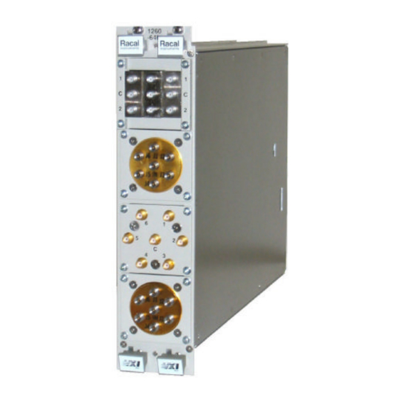
CONNECTOR PIN CONFIGURATION Figure 4-1 shows the location of four plug-ins on the front panel RF Relays of the 1260-64M module. The actual configuration is application dependent. Figure 4-2 shows the pin locations for the 50-pin Relay Bank Relay Banks connector, J1. -
Page 45: Figure 4-1, 1260-64M Front Panel
User Manual 1260-64M Figure 4-1, 1260-64M Front Panel ©2002 Connector Pin Configuration 4-2 Racal Instruments Artisan Scientific - Quality Instrumentation ... Guaranteed | (888) 88-SOURCE | www.artisan-scientific.com... -
Page 46: Figure 1-1, 1260-64M
User Manual 1260-64M Table 4-1, 1260-64M Pin Assignments BankA BankB Function Function A,C,E,H External B+ B,D,F,J External B+ X, y, z, AA External Ground CC,DD,EE External Ground z, AA, BB External Ground FF,HH External Ground Contact 0 Contact 0 Contact 1... -
Page 47: Figure 4-3, Internal Supply Sink Driver Example
User Manual 1260-64M +12V +24V EXTERNAL B+ EXTERNAL GROUND EXTERNAL RELAY CONTACT 0 CONTACT 1 CONTACT 3 CONTACT 3 CONTACT 4 CONTACT 5 CONTACT 6 Figure 4-3, Internal Supply Sink Driver Example +24V +12V EXTERNAL SUPPLY EXTERNAL B+ EXTERNAL GROUND... -
Page 48: Figure 4-5, Internal Supply Source Driver Example
User Manual 1260-64M +12V +24V EXTERNAL B+ EXTERNAL GROUND CONTACT 0 CONTACT 1 CONTACT 3 EXTERNAL RELAY CONTACT 3 CONTACT 4 CONTACT 5 CONTACT 6 Figure 4-5, Internal Supply Source Driver Example +24V +12V EXTERNAL SUPPLY EXTERNAL B+ EXTERNAL GROUND... - Page 49 User Manual 1260-64M This page was left intentionally blank. ©2002 Connector Pin Configuration 4-6 Racal Instruments Artisan Scientific - Quality Instrumentation ... Guaranteed | (888) 88-SOURCE | www.artisan-scientific.com...
-
Page 50: Chapter 5 Theory Of Operation
User Manual 1260-64M Chapter 5 THEORY OF OPERATION The 1260-64M consists of two PCB assemblies. A small PCB PCB Assemblies assembly is required to pass the local bus signals, LBUS 0 through LBUS 11, through the unused second slot of this double-wide module. - Page 51 User Manual 1260-64M This page was left intentionally blank. ©2002 Theory of Operation 5-2 Racal Instruments Artisan Scientific - Quality Instrumentation ... Guaranteed | (888) 88-SOURCE | www.artisan-scientific.com...
-
Page 52: Chapter 6 Product Support
For worldwide support and the office closes to your facility, refer to the Support Offices section on the following page. Use the original packing material when returning the 1260-64M to Reshipment Racal Instruments for calibration or servicing. The original... -
Page 53: Support Offices
User Manual 1260-64M Racal Instruments, Inc. Support Offices 4 Goodyear St., Irvine, CA 92618-2002 Tel: (800) RACAL-ATE, (800) 722-2528, (949) 859-8999; FAX: (949) 859-7139 Racal Instruments, Ltd. 480 Bath Road, Slough, Berkshire, SL1 6BE, United Kingdom Tel: +44 (0) 1628 604455; FAX: +44 (0) 1628 662017 Racal Systems Electronique S.A. -
Page 54: Repair And Calibration Request Form
User Manual 1260-64M REPAIR AND CALIBRATION REQUEST FORM To allow us to better understand your repair requests, we suggest you use the following outline when calling and include a copy with your instrument to be sent to the Racal Repair Facility.