Table of Contents
Advertisement
Quick Links
Advertisement
Table of Contents

Related Manuals for Racal Instruments 1260 Series


Summary of Contents for Racal Instruments 1260 Series
- Page 1 Artisan Technology Group is your source for quality new and certified-used/pre-owned equipment SERVICE CENTER REPAIRS WE BUY USED EQUIPMENT • FAST SHIPPING AND DELIVERY Experienced engineers and technicians on staff Sell your excess, underutilized, and idle used equipment at our full-service, in-house repair center We also offer credit for buy-backs and trade-ins •...
- Page 2 PUBLICATION DATE: April 10, 2000 Copyright 1997 by Racal Instruments, Inc. Printed in the United States of America. All rights reserved. This book or parts thereof may not be reproduced in any form without written permission of the publisher.
- Page 3 Authorization is required from Racal Instruments before you send us your product for service or calibration. Call your nearest Racal Instruments support facility. A list is located on the last page of this manual. If you are unsure where to call, contact Racal Instruments, Inc. Customer Support Department in Irvine, California, USA at...
- Page 4 FOR YOUR SAFETY Before undertaking any troubleshooting, maintenance or exploratory procedure, read carefully the WARNINGS and CAUTION notices. This equipment contains voltage hazardous to human life and safety, and is capable of inflicting personal injury. If this instrument is to be powered from the AC line (mains) through an autotransformer, ensure the common connector is connected to the neutral (earth pole) of the power supply.
- Page 5 This page was left intentionally blank. Artisan Technology Group - Quality Instrumentation ... Guaranteed | (888) 88-SOURCE | www.artisantg.com...
- Page 6 NOTE FOR SYSTEMS WITH 1260-OPT 01T The “Module-Specific Syntax” section of this manual shows the command syntax for the 1260-01S Smart Card. If you are using the newer 1260-01T Smart Card, the commands will NOT work as shown. Consult the 1260-01T Manual for a description of the commands that may be used with the 1260-01T Smart Card.
- Page 7 Control Information for the 1260-35A The 1260-35A operates as a 4-wire MUX. Thus, when a channel is operated, 2 relays must be operated in parallel. For each channel, when a bit of Control Register X is set (or cleared), the same bit of Control Register X+6 must also be set (or cleared).
- Page 8 Channel Control Register Control Bit 5 and 11 5 and 11 5 and 11 5 and 11 5 and 11 5 and 11 5 and 11 5 and 11 Artisan Technology Group - Quality Instrumentation ... Guaranteed | (888) 88-SOURCE | www.artisantg.com...
- Page 9 Control Information for the 1260-35B The following information describes the control-register-to-relay-channel mapping for a 1260-35B Relay Module. This information may be used to control a 1260-35B when using a 1260-01T in the register-based mode of operation. Each relay on this module is controlled by setting or clearing a single bit within a Control Register. Control Registers on the module operate 8 channels simultaneously.
- Page 10 Channel Control Register Control Bit Artisan Technology Group - Quality Instrumentation ... Guaranteed | (888) 88-SOURCE | www.artisantg.com...
-
Page 11: Table Of Contents
User Manual 1260-35 Table of Contents Chapter 1 MODULE SPECIFICATION ......................1-1 1260-35 Module Specification ....................1-1 Specifications ........................1-2 Ordering Information ......................... 1-3 Safety............................1-3 Product Support ........................1-3 Chapter 2 INSTALLATION INSTRUCTIONS ....................2-1 Unpacking and Inspection ......................2-1 Reshipment Instructions...................... - Page 12 User Manual 1260-35 Chapter 6 OPTIONAL HARNESS ASSEMBLIES..................6-1 Chapter 7 PRODUCT SUPPORT ......................... 7-1 Product Support........................7-1 Reshipment Instructions ......................7-1 Support Offices ......................... 7-2 Artisan Technology Group - Quality Instrumentation ... Guaranteed | (888) 88-SOURCE | www.artisantg.com...
- Page 13 User Manual 1260-35 List of Figures Figure 1-1, 1260-35 Signal Multiplexer/Scanner Module............... 1-1 Figure 3-1, 1260-35 Block Diagram ....................3-7 Figure 3-2, 1260-35 Pin Connections, Front View................. 3-8 List of Tables Table 2-1, 1260-35 Jumper Installation..................2-3 Table 3-1, 1260-35 Channel Closure .................... 3-3 Table 3-1, 1260-35 Channel Closure (continued) .................
- Page 14 User Manual 1260-35 This page was left intentionally blank. Artisan Technology Group - Quality Instrumentation ... Guaranteed | (888) 88-SOURCE | www.artisantg.com...
-
Page 15: Module Specification
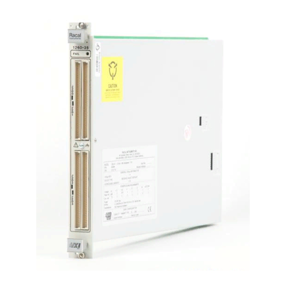
User Manual 1260-35 Chapter 1 MODULE SPECIFICATION The 1260-35 Signal Multiplexer/Scanner Module is a 1 x 96 1260-35 Module multiplexer. It switches two lines per channel and has the Specification capability of being configured as two 1 x 48 multiplexers, four 1 x 24 multiplexers, eight 1 x 12 multiplexers, or sixteen 1 x 6 multiplexers. -
Page 16: Specifications
User Manual 1260-35 Switch Configurations Specifications Four-wire Mode Any configuration Two-wire Mode Any configuration User Connector 64-Pin (2 Row) IDC Quick Disconnect Maximum Switchable Voltage 220VDC, 250VAC RMS (Terminal-Terminal or Terminal-Chassis Maximum Switchable Current 1A DC or 1A RMS Maximum Switchable Power Per Channel 30W DC, 62.5VA AC Path Resistance... -
Page 17: Ordering Information
Contents. Following all NOTES, CAUTIONS, and WARNINGS to ensure personal safety and prevent damage to the instrument. Racal Instruments has a complete Service and Parts Department. Product Support If you need technical assistance or should it be necessary to return your product for servicing, call 1-800-722-3262. - Page 18 User Manual 1260-35 This page was left intentionally blank. Module Specification 1-4 Artisan Technology Group - Quality Instrumentation ... Guaranteed | (888) 88-SOURCE | www.artisantg.com...
-
Page 19: Installation Instructions
Series cards. Failure to do so may cause damage to the unit. 1. Use the original packing material when returning the switching Reshipment module to Racal Instruments for servicing. The original Instructions shipping carton and the instrument's plastic foam will provide the necessary support for safe reshipment. -
Page 20: Module Installation
User Manual 1260-35 Installation of the Option 01 to the 1260-35 is described in the Option 01 Installation section of the 1260 Series VXI Switching Cards Installation Manual. Installation of the 1260-35 Switching Module into a VXI mainframe, Module including the setting of DIP switches, is described in the... -
Page 21: Table 2-1, 1260-35 Jumper Installation
User Manual 1260-35 necessary information to configure the module into the other possible configurations Table 2-1, 1260-35 Jumper Installation An X indicates a jumper is to be fitted. An (X) indicates the jumper is optional depending on whether access to the analog bus is required. A blank indicates no jumper is to be fitted. 16(1x6) 8(1x6) 8(1x12) -
Page 22: Analog Bus
User Manual 1260-35 In most of the above configurations, the 1260-35 may be user Analog Bus configured to access an analog bus (refer to Figure 3-1). The analog bus allows internal expansion for the configuration of larger scanner/multiplexers than the module may achieve alone, by providing access to a common bus channel which may be daisy chained to other modules via the front panel. -
Page 23: Module Specific Syntax
RESET command, VXI hard or soft reset, or power-off. NOTE The <module address> used here is NOT the VXIbus defined logical address of the 1260 Series Master. It is peculiar to the 1260 Series and describes the switching module in relation to the Master. This address corresponds to the binary value of the switch setting of SW1 on the switching module PCB. -
Page 24: Close Command
User Manual 1260-35 Example: OPEN 3.02 This open command will open channel 2 on the module at switch card address 3 The Module Specific Syntax for the CLOSE command is the same CLOSE Command as for the OPEN command. The PSETUP command causes the specified module setup to be PSETUP transmitted to the VXI Controller. -
Page 25: Operation In Single-Wire Mode
User Manual 1260-35 module to the 1260 Controller. The syntax used is: Command PDATAOUT <module address>[.<module address>] [;<module address>]….. The responses to the PDATAOUT command is as follows: 1260-35: Two-wire <module address>. 1260-3 SB Two-wire Scanner/Multiplexer Module <module address>. <channel>[,<channel>] [,<channel>] <module address>.END 1260-35 Four-wire... - Page 26 User Manual 1260-35 channel interconnect for 1, 2 and 4-wire modes. 1-wire mode: <channel> <channel> output <channel> input (channel 96 open) 0 thru 95 always J202- B2 (see 2-wire mode channels 0-95 input pins b-side of channel) (channel 96 closed) 0 thru 95 always J202- B2 (see 2-wire mode channels 0-95...
-
Page 27: Table 3-1, 1260-35 Channel Closure (Continued)
User Manual 1260-35 Table 3-1, 1260-35 Channel Closure (continued) J202 A22 / B22 J202 A23 I B23 J202 A23 / B23 J202 A21 / B21 J202 A23 / B23 J202 A20 / B20 J202 A23 / B23 J202 A19 / B19 J202 A23 / B23 J202 A18 / B18 J202 A23 / B23... - Page 28 User Manual 1260-35 Table 3-1, 1260-35 Channel Closure (continued) J203 A23 / B23 J203 A22 / B22 J203 A23 / B23 J203 A21 / B21 J203 A23 / B23 J203 A20 / B20 J203 A23 / B23 J203 A19 / B19 J203 A23 / B23 J203 A18 / B18 J203 A23 / B23...
-
Page 29: Figure 3-1, 1260-35 Block Diagram
User Manual 1260-35 Figure 3-1, 1260-35 Block Diagram Module Specific Syntax 3-7 Artisan Technology Group - Quality Instrumentation ... Guaranteed | (888) 88-SOURCE | www.artisantg.com... -
Page 30: Figure 3-2, 1260-35 Pin Connections, Front View
User Manual 1260-35 Figure 3-2, 1260-35 Pin Connections, Front View Module Specific Syntax 3-8 Artisan Technology Group - Quality Instrumentation ... Guaranteed | (888) 88-SOURCE | www.artisantg.com... -
Page 31: Drawings
User Manual 1260-35 Chapter 4 DRAWINGS 404944 Final Assy, 1260-35 (IDC Connectors) ........... 4-3 404944-001 Final Assy, 1260-35A (Crimp Connectors) ..........4-4 401989 PCB Assy, 1260-35.................. 4-5 431989 Schematic, 1260-35.................. 4-7 401992 PCB Assy, 1260-35D................4-24 431992 Schematic, 1260-35D................4-25 Drawings 4-1 Artisan Technology Group - Quality Instrumentation ... - Page 32 User Manual 1260-35 Drawings 4-2 Artisan Technology Group - Quality Instrumentation ... Guaranteed | (888) 88-SOURCE | www.artisantg.com...
- Page 33 User Manual 1260-35 DOC. 404944 Drawings 4-3 Artisan Technology Group - Quality Instrumentation ... Guaranteed | (888) 88-SOURCE | www.artisantg.com...
- Page 34 User Manual 1260-35 DOC. 404944-001 Drawings 4-4 Artisan Technology Group - Quality Instrumentation ... Guaranteed | (888) 88-SOURCE | www.artisantg.com...
- Page 35 User Manual 1260-35 Drawings 4-5 Artisan Technology Group - Quality Instrumentation ... Guaranteed | (888) 88-SOURCE | www.artisantg.com...
- Page 36 User Manual 1260-35 Drawings 4-6 Artisan Technology Group - Quality Instrumentation ... Guaranteed | (888) 88-SOURCE | www.artisantg.com...
- Page 37 User Manual 1260-35 Drawings 4-7 Artisan Technology Group - Quality Instrumentation ... Guaranteed | (888) 88-SOURCE | www.artisantg.com...
- Page 38 User Manual 1260-35 Drawings 4-8 Artisan Technology Group - Quality Instrumentation ... Guaranteed | (888) 88-SOURCE | www.artisantg.com...
- Page 39 User Manual 1260-35 Drawings 4-9 Artisan Technology Group - Quality Instrumentation ... Guaranteed | (888) 88-SOURCE | www.artisantg.com...
- Page 40 User Manual 1260-35 Drawings 4-10 Artisan Technology Group - Quality Instrumentation ... Guaranteed | (888) 88-SOURCE | www.artisantg.com...
- Page 41 User Manual 1260-35 Drawings 4-11 Artisan Technology Group - Quality Instrumentation ... Guaranteed | (888) 88-SOURCE | www.artisantg.com...
- Page 42 User Manual 1260-35 Drawings 4-12 Artisan Technology Group - Quality Instrumentation ... Guaranteed | (888) 88-SOURCE | www.artisantg.com...
- Page 43 User Manual 1260-35 Drawings 4-13 Artisan Technology Group - Quality Instrumentation ... Guaranteed | (888) 88-SOURCE | www.artisantg.com...
- Page 44 User Manual 1260-35 Drawings 4-14 Artisan Technology Group - Quality Instrumentation ... Guaranteed | (888) 88-SOURCE | www.artisantg.com...
- Page 45 User Manual 1260-35 Drawings 4-15 Artisan Technology Group - Quality Instrumentation ... Guaranteed | (888) 88-SOURCE | www.artisantg.com...
- Page 46 User Manual 1260-35 Drawings 4-16 Artisan Technology Group - Quality Instrumentation ... Guaranteed | (888) 88-SOURCE | www.artisantg.com...
- Page 47 User Manual 1260-35 Drawings 4-17 Artisan Technology Group - Quality Instrumentation ... Guaranteed | (888) 88-SOURCE | www.artisantg.com...
- Page 48 User Manual 1260-35 Drawings 4-18 Artisan Technology Group - Quality Instrumentation ... Guaranteed | (888) 88-SOURCE | www.artisantg.com...
- Page 49 User Manual 1260-35 Drawings 4-19 Artisan Technology Group - Quality Instrumentation ... Guaranteed | (888) 88-SOURCE | www.artisantg.com...
- Page 50 User Manual 1260-35 Drawings 4-20 Artisan Technology Group - Quality Instrumentation ... Guaranteed | (888) 88-SOURCE | www.artisantg.com...
- Page 51 User Manual 1260-35 Drawings 4-21 Artisan Technology Group - Quality Instrumentation ... Guaranteed | (888) 88-SOURCE | www.artisantg.com...
- Page 52 User Manual 1260-35 Drawings 4-22 Artisan Technology Group - Quality Instrumentation ... Guaranteed | (888) 88-SOURCE | www.artisantg.com...
- Page 53 User Manual 1260-35 Drawings 4-23 Artisan Technology Group - Quality Instrumentation ... Guaranteed | (888) 88-SOURCE | www.artisantg.com...
- Page 54 User Manual 1260-35 Drawings 4-24 Artisan Technology Group - Quality Instrumentation ... Guaranteed | (888) 88-SOURCE | www.artisantg.com...
- Page 55 User Manual 1260-35 Drawings 4-25 Artisan Technology Group - Quality Instrumentation ... Guaranteed | (888) 88-SOURCE | www.artisantg.com...
- Page 56 User Manual 1260-35 Drawings 4-26 Artisan Technology Group - Quality Instrumentation ... Guaranteed | (888) 88-SOURCE | www.artisantg.com...
- Page 57 User Manual 1260-35 Drawings 4-27 Artisan Technology Group - Quality Instrumentation ... Guaranteed | (888) 88-SOURCE | www.artisantg.com...
- Page 58 User Manual 1260-35 Drawings 4-28 Artisan Technology Group - Quality Instrumentation ... Guaranteed | (888) 88-SOURCE | www.artisantg.com...
- Page 59 User Manual 1260-35 Drawings 4-29 Artisan Technology Group - Quality Instrumentation ... Guaranteed | (888) 88-SOURCE | www.artisantg.com...
- Page 60 User Manual 1260-35 Drawings 4-30 Artisan Technology Group - Quality Instrumentation ... Guaranteed | (888) 88-SOURCE | www.artisantg.com...
-
Page 61: Parts List
User Manual 1260-35 Chapter 5 PARTS LIST 404944 Final Assembly, 1260-35 (IDC Connector) 404975 Shipping Kit, 1260-35 404944-001 Final Assembly, 1260-35A (Crimp Connectors) 404975-001 Shipping Kit, 1260-35A 401989 PCB Assy, 1260-35 401992 PCB Assy, 1260-35D 5-10 List of Suppliers 5-11 Parts List 5-1 Artisan Technology Group - Quality Instrumentation ... - Page 62 User Manual 1260-35 This page was left intentionally blank. Parts List 5-2 Artisan Technology Group - Quality Instrumentation ... Guaranteed | (888) 88-SOURCE | www.artisantg.com...
- Page 63 User Manual 1260-35 Parts List 5-3 Artisan Technology Group - Quality Instrumentation ... Guaranteed | (888) 88-SOURCE | www.artisantg.com...
- Page 64 User Manual 1260-35 Parts List 5-4 Artisan Technology Group - Quality Instrumentation ... Guaranteed | (888) 88-SOURCE | www.artisantg.com...
- Page 65 User Manual 1260-35 Parts List 5-5 Artisan Technology Group - Quality Instrumentation ... Guaranteed | (888) 88-SOURCE | www.artisantg.com...
- Page 66 User Manual 1260-35 Parts List 5-6 Artisan Technology Group - Quality Instrumentation ... Guaranteed | (888) 88-SOURCE | www.artisantg.com...
- Page 67 User Manual 1260-35 Parts List 5-7 Artisan Technology Group - Quality Instrumentation ... Guaranteed | (888) 88-SOURCE | www.artisantg.com...
- Page 68 User Manual 1260-35 Parts List 5-8 Artisan Technology Group - Quality Instrumentation ... Guaranteed | (888) 88-SOURCE | www.artisantg.com...
- Page 69 User Manual 1260-35 Parts List 5-9 Artisan Technology Group - Quality Instrumentation ... Guaranteed | (888) 88-SOURCE | www.artisantg.com...
- Page 70 User Manual 1260-35 Parts List 5-10 Artisan Technology Group - Quality Instrumentation ... Guaranteed | (888) 88-SOURCE | www.artisantg.com...
- Page 71 User Manual 1260-35 Parts List 5-11 Artisan Technology Group - Quality Instrumentation ... Guaranteed | (888) 88-SOURCE | www.artisantg.com...
- Page 72 User Manual 1260-35 This page was left intentionally blank. Parts List 5-12 Artisan Technology Group - Quality Instrumentation ... Guaranteed | (888) 88-SOURCE | www.artisantg.com...
-
Page 73: Optional Harness Assemblies
User Manual 1260-35 Chapter 6 OPTIONAL HARNESS ASSEMBLIES The following harness assemblies are used to connect Racal Instruments Model 1260-35 to Freedom Series Test Receiver Interfaces. Each harness documentation consists of an assembly drawing, parts list, system wire list and wire list. - Page 74 User Manual 1260-35 This page was left intentionally blank. Optional Harness Assemblies 6-2 Artisan Technology Group - Quality Instrumentation ... Guaranteed | (888) 88-SOURCE | www.artisantg.com...
- Page 75 User Manual 1260-35 407280 DWG. NO. REV. Optional Harness Assemblies 6-3 Artisan Technology Group - Quality Instrumentation ... Guaranteed | (888) 88-SOURCE | www.artisantg.com...
- Page 76 User Manual 1260-35 RACAL INSTRUMENTS INC. Assembly 407280 HARNESS ASSY, 1260-35, VP90 Date 3/18/99 Revision D Component Description Qty Reqd 405084 PCB ASSY, VP90 INTFC, 64CONTCT 1.00000 405085 PCB ASSY, VP90 INTFC, 96CONTCT 2.00000 407259 CABLE ASSY, IDC, 64COND,VP90 3.00000...
- Page 77 User Manual 1260-35 Optional Harness Assemblies 6-5 Artisan Technology Group - Quality Instrumentation ... Guaranteed | (888) 88-SOURCE | www.artisantg.com...
- Page 78 User Manual 1260-35 Optional Harness Assemblies 6-6 Artisan Technology Group - Quality Instrumentation ... Guaranteed | (888) 88-SOURCE | www.artisantg.com...
- Page 79 User Manual 1260-35 Optional Harness Assemblies 6-7 Artisan Technology Group - Quality Instrumentation ... Guaranteed | (888) 88-SOURCE | www.artisantg.com...
- Page 80 User Manual 1260-35 Optional Harness Assemblies 6-8 Artisan Technology Group - Quality Instrumentation ... Guaranteed | (888) 88-SOURCE | www.artisantg.com...
- Page 81 User Manual 1260-35 Optional Harness Assemblies 6-9 Artisan Technology Group - Quality Instrumentation ... Guaranteed | (888) 88-SOURCE | www.artisantg.com...
- Page 82 User Manual 1260-35 Optional Harness Assemblies 6-10 Artisan Technology Group - Quality Instrumentation ... Guaranteed | (888) 88-SOURCE | www.artisantg.com...
- Page 83 User Manual 1260-35 Optional Harness Assemblies 6-11 Artisan Technology Group - Quality Instrumentation ... Guaranteed | (888) 88-SOURCE | www.artisantg.com...
- Page 84 User Manual 1260-35 Optional Harness Assemblies 6-12 Artisan Technology Group - Quality Instrumentation ... Guaranteed | (888) 88-SOURCE | www.artisantg.com...
- Page 85 User Manual 1260-35 Optional Harness Assemblies 6-13 Artisan Technology Group - Quality Instrumentation ... Guaranteed | (888) 88-SOURCE | www.artisantg.com...
- Page 86 User Manual 1260-35 Optional Harness Assemblies 6-14 Artisan Technology Group - Quality Instrumentation ... Guaranteed | (888) 88-SOURCE | www.artisantg.com...
- Page 87 User Manual 1260-35 Optional Harness Assemblies 6-15 Artisan Technology Group - Quality Instrumentation ... Guaranteed | (888) 88-SOURCE | www.artisantg.com...
- Page 88 User Manual 1260-35 Optional Harness Assemblies 6-16 Artisan Technology Group - Quality Instrumentation ... Guaranteed | (888) 88-SOURCE | www.artisantg.com...
- Page 89 User Manual 1260-35 Optional Harness Assemblies 6-17 Artisan Technology Group - Quality Instrumentation ... Guaranteed | (888) 88-SOURCE | www.artisantg.com...
- Page 90 User Manual 1260-35 Optional Harness Assemblies 6-18 Artisan Technology Group - Quality Instrumentation ... Guaranteed | (888) 88-SOURCE | www.artisantg.com...
- Page 91 User Manual 1260-35 Optional Harness Assemblies 6-19 Artisan Technology Group - Quality Instrumentation ... Guaranteed | (888) 88-SOURCE | www.artisantg.com...
- Page 92 User Manual 1260-35 Optional Harness Assemblies 6-20 Artisan Technology Group - Quality Instrumentation ... Guaranteed | (888) 88-SOURCE | www.artisantg.com...
- Page 93 User Manual 1260-35 Optional Harness Assemblies 6-21 Artisan Technology Group - Quality Instrumentation ... Guaranteed | (888) 88-SOURCE | www.artisantg.com...
- Page 94 User Manual 1260-35 Optional Harness Assemblies 6-22 Artisan Technology Group - Quality Instrumentation ... Guaranteed | (888) 88-SOURCE | www.artisantg.com...
-
Page 95: Chapter 7 Product Support
User Manual 1260-35 Chapter 7 PRODUCT SUPPORT Racal Instruments has a complete Service and Parts Department. Product Support If you need technical assistance or should it be necessary to return your product for repair or calibration, call 1-800-722-3262. If parts are required to repair the product at your facility, call 1-949-859- 8999 and ask for the Parts Department. -
Page 96: Support Offices
User Manual 1260-35 Support Offices Racal Instruments, Inc. 4 Goodyear St., Irvine, CA 92618-2002 Tel: (800) 722-3262, FAX: (949) 859-7309 Racal Instruments, Ltd. 480 Bath Road, Slough, Berkshire, SL1 6BE, United Kingdom Tel: +44 (0) 8706 080134; FAX: +44 (0) 1753 791290 Racal Systems Electronique S.A. - Page 97 Artisan Technology Group is your source for quality new and certified-used/pre-owned equipment SERVICE CENTER REPAIRS WE BUY USED EQUIPMENT • FAST SHIPPING AND DELIVERY Experienced engineers and technicians on staff Sell your excess, underutilized, and idle used equipment at our full-service, in-house repair center We also offer credit for buy-backs and trade-ins •...