
Related Manuals for Racal Instruments 1260


Summary of Contents for Racal Instruments 1260
- Page 1 (217) 352-9330 | Click HERE Find the Astronics / EADS / Racal 1260-18 at our website:...
- Page 2 PUBLICATION DATE: June 28, 1999 Copyright 1999 by Racal Instruments, Inc. Printed in the United States of America. All rights reserved. This book or parts thereof may not be reproduced in any form without written permission of the publisher.
- Page 3 Authorization is required from Racal Instruments before you send us your product for service or calibration. Call your nearest Racal Instruments support facility. A list is located on the last page of this manual. If you are unsure where to call, contact Racal Instruments, Inc. Customer Support Department in Irvine, California, USA at...
- Page 4 FOR YOUR SAFETY Before undertaking any troubleshooting, maintenance or exploratory procedure, read carefully the WARNINGS and CAUTION notices. This equipment contains voltage hazardous to human life and safety, and is capable of inflicting personal injury. If this instrument is to be powered from the AC line (mains) through an autotransformer, ensure the common connector is connected to the neutral (earth pole) of the power supply.
- Page 5 This page was left intentionally blank.
- Page 6 1260-01S Smart Card. If you are using the newer 1260-01T Smart Card, the commands will NOT work as shown. Consult the 1260-01T Manual for a description of the commands that may be used with the 1260-01T Smart Card. The channel numbers described in this manual are valid for the 1260-01T. The channel numbers continue to be used for the 1260-01T.
- Page 7 Each Control Register is located 2 addresses from the previous Control Register. That is, each Control Register is located at an odd address. This is shown in Table 2-2 of the 1260-01T manual. Control Register 0 is located at the “Base A24 Address” for the module. Consult the “Register-Based Operation” Section of...
- Page 8 Channel Control Register Control Bit...
- Page 9 Channel Control Register Control Bit 152* 153* 154* 155* 156* 157* 158* 159* *These control bits exist, but the relays are not normally populated on the module.
-
Page 10: Table Of Contents
Chapter 3 MODULE OPERATION ........................ 3-1 Module Configuration ........................ 3-1 Front Panel Connectors......................3-1 Mating Connectors ......................3-1 1260-18 Module Specific Syntax.................... 3-2 1260-18 Relay Descriptors....................3-2 1260-18 INCL Command ....................3-4 CLOSE Command ......................3-6 OPEN Command ....................... 3-7 EXCL Command ........................ - Page 11 User Manual 1260-18 Chapter 4 DRAWINGS ..........................4-1 Chapter 5 PARTS LIST..........................5-1 Chapter 6 OPTIONAL HARNESS ASSEMBLIES..................6-1 Chapter 7 PRODUCT SUPPORT ......................... 7-1 Product Support........................7-1 Reshipment Instructions ......................7-1 Support Offices ......................... 7-2...
- Page 12 User Manual 1260-18 List Of Figures Figure 1-1, 1260-18 High Density Basic Switch ................1-1 Figure 3-1, Module Configuration Block Diagram ............... 3-11 Figure 3-2, 1260-18 Pin Connections, Front View............... 3-12 List of Tables Table 3-1. 1260-18 Channel Number/Connection Pin/Cable Mapping ........3-13 Table 3-1.
- Page 13 User Manual 1260-18 This page was left intentionally blank.
-
Page 14: Module Specification
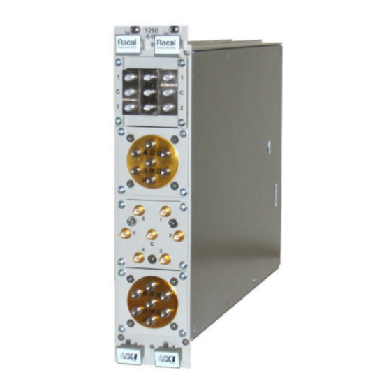
User Manual 1260-18 Chapter 1 MODULE SPECIFICATION The 1260-18 high density basic switch is a 152 channel single-wire Module device capable of being configured in many ways. For example, it Specification can be configured as 152 SPST switches, or 76 SPDT switches, or 50 SP3T switches, etc. -
Page 15: Specifications
User Manual 1260-18 Maximum Switch Power 125VA, 60W Specifications Maximum Switch Voltage 250VAC, 220VDC Maximum Switch Current 2A AC, 2A DC Bandwidth (50Ω ) > 50MHz Insertion Loss (50Ω ) < 3dB @ 50MHz < 2dB to 10MHz < 1dB to 1MHz Crosstalk (50Ω... -
Page 16: Ordering Information
With Option 01 installed 3.5lb (1.60kg) Minimum Option 01 Firmware Revision 29.1 (T) Listed below are part numbers for both the 1260-18 Switch Module Ordering and available mating connector accessories (see also Chapter 3). Information Each switch card uses 2 mating connectors. -
Page 17: Safety
Contents. Follow all NOTES, CAUTIONS and WARNINGS to ensure personal safety and prevent damage to the instrument. Racal Instruments has a complete Service and Parts Department. Product Support If you need technical assistance or should it be necessary to return your product for servicing, call 1-800-722-3262 or 1-949-859-8999 and ask for Customer Support. -
Page 18: Installation Instructions
4. Have a qualified person check the instrument for safety before use. CAUTION Proper ESD handling procedures must always be used when packing, unpacking or installing any 1260 Series cards. Failure to do so may cause damage to the unit. 1. Use the original packing material when returning the... -
Page 19: Option 01 Installation
User Manual 1260-18 Installation of the Option 01 to the 1260-18 is described in the Option 01 Installation section of the 1260 Series VXI Switching Cards Installation Manual, under the Option 01 installation section.. Installation of the 1260-18 Switching Module into a VXI mainframe,... -
Page 20: Chapter 3 Module Operation
User Manual 1260-18 Chapter 3 MODULE OPERATION The 1260-18 is a 152 channel single wire module consisting of 152 Module individual SPST relay switches. These individual relays allow the Configuration 1260-18 module to be configured via software in any configuration from 152 - SPST’s to 1 - 152PST or any combination thereof (by... -
Page 21: 1260-18 Module Specific Syntax
The 1260-18 card supports nearly all of the 1260 commands 1260-18 Module described in Section 3.4 of the 1260 Option 01 manual. The only Specific Syntax commands which are NOT supported are the READ and WRITE commands. - Page 22 Each relay is identified by a single number in the range 0 to 151. The following examples, using the CLOSE command, show the various formats which are used for 1260-18 relay descriptors. Each of the samples shows a module address of 7 for the 1260-18 CLOSE 7.0 -- close channel 0 CLOSE 7.0,5...
-
Page 23: 1260-18 Incl Command
User Manual 1260-18 The 1260-18 uses the command INCL to equate two or more 1260-18 INCL relays within a single module. When a relay is included with other Command relays, then closing that relay will close all relays included with the closed relay. - Page 24 The syntax for this use is: INCL When the INCL command is used with no parameters, the 1260 Option 01 will reply with a series of reply lines. Each reply line will correspond to a single include group. The final reply line will be the string: and will be terminated with an ASCII carriage return and linefeed.
-
Page 25: Close Command
User Manual 1260-18 7.023,025,027,029 7.034,057,110,151 7.004,033,034,035,036,037,038,039 This example shows that 5 include groups have been defined. If the reply to this command takes more than 80 characters to indicate a single include group, then the reply line will be terminated with a semicolon before the carriage return and linefeed. -
Page 26: Open Command
The EXCL command uses the syntax: EXCL <exclude list> [E; <exclude list> ] where: <exclude list> is a list of two or more relay descriptors. The relays do NOT have to be on the same 1260 module, nor do Module Specific Syntax 3-7... -
Page 27: Pdataout And Psetup Module Identification
XXX is the module address of the 1260-18 ("001" to "012"). All other reply lines for these commands shall follow the syntax used for all of the other 1260 series relay cards. Note that the lines of the reply for the PDATAOUT command will contain relay descriptors which follow the syntax described in this chapter. -
Page 28: Pdataout Command
A minimum of three reply lines are returned. The FIRST line is as follows: <module>. 1260-18 HIGH DENSITY BASIC SWITCH MODULE where module is the module address of the 1260-18 card ("000" to "012"). The LAST line is as follows: <module>.END Note that there is no space character between the period and the "E"... -
Page 29: Psetup Command
<module address> is the switch card address. The response to the PSETUP command for the 1260-18 consists of three lines. Each line consists of a three-digit module address, followed by some information. A sample reply to the PSETUP command is shown below: 007. -
Page 30: Figure 3-1, Module Configuration Block Diagram
User Manual 1260-18 Before-Break (“MBB”), and Immediate (“IMM”). The setup mode may be changed using the “SETUP” command, described in section 3.4 of the 1260 Option 01 manual. The last line containing the "END" characters denotes no more information to report. -
Page 31: Figure 3-2, 1260-18 Pin Connections, Front View
User Manual 1260-18 a b c d e 1260-18 FAIL Figure 3-2, 1260-18 Pin Connections, Front View Module Specific Syntax 3-12... -
Page 32: Table 3-1. 1260-18 Channel Number/Connection Pin/Cable Mapping
User Manual 1260-18 Table 3-1. 1260-18 Channel Number/Connection Pin/Cable Mapping Channel # Connector Pin # Cable # / Color 0000 In J200-P31A C1 white/black/orange/violet 0000 Out J200-P29A C1 white/black/brown/violet 0001 In J200-P30A C1 white/black/red/violet 0001 Out J200-P28A C1 white/black/brown/red 0002 In... -
Page 33: Table 3-1. 1260-18 Channel Number/Connection Pin/Cable Mapping (Continued)
User Manual 1260-18 Table 3-1. 1260-18 Channel Number/Connection Pin/Cable Mapping Channel # Connector Pin # Cable # / Color 0012 In J200-P27B C1 white/green/grey 0012 Out J200-P25B C1 white/orange/green 0013 In J200-P26B C1 white/yellow/blue 0013 Out J200-P24B C1 white/red/green 0014 In... - Page 34 User Manual 1260-18 Table 3-1. 1260-18 Channel Number/Connection Pin/Cable Mapping Channel # Connector Pin # Cable # / Color 0024 In J200-P23C C1 white/brown/violet 0024 Out J200-P21C C1 white/black/yellow 0025 In J200-P22C C1 white/brown/red 0025 Out J200-P20C C1 white/violet 0026 In...
-
Page 35: Table 3-1. 1260-18 Channel Number/Connection Pin/Cable Mapping (Continued)
User Manual 1260-18 Table 3-1. 1260-18 Channel Number/Connection Pin/Cable Mapping Channel # Connector Pin # Cable # / Color 0036 In J200-P19D C1 white/orange 0036 Out J200-P17D C1 orange 0037 In J200-P18D C1 grey 0037 Out J200-P16D C2 white/black/green/grey 0038 In... -
Page 36: Table 3-1. 1260-18 Channel Number/Connection Pin/Cable Mapping (Continued)
User Manual 1260-18 Table 3-1. 1260-18 Channel Number/Connection Pin/Cable Mapping Channel # Connector Pin # Cable # / Color 0048 In J200-P15E C2 white/black/yellow/violet 0048 Out J200-P13E C2 white/black/red/blue 0049 In J200-P14E C2 white/black/orange/blue 0049 Out J200-P12E C2 white/black/brown/blue 0050 In... -
Page 37: Table 3-1. 1260-18 Channel Number/Connection Pin/Cable Mapping (Continued)
User Manual 1260-18 Table 3-1. 1260-18 Channel Number/Connection Pin/Cable Mapping Channel # Connector Pin # Cable # / Color 0060 In J200-P07A C2 white/brown/green 0060 Out J200-P05A C2 white/black/red 0061 In J200-P06A C2 white/black/violet 0061 Out J200-P04A C2 white/green 0062 In... -
Page 38: Table 3-1. 1260-18 Channel Number/Connection Pin/Cable Mapping (Continued)
User Manual 1260-18 Table 3-1. 1260-18 Channel Number/Connection Pin/Cable Mapping Channel # Connector Pin # Cable # / Color 0072 In J200-P03B C2 white/brown 0072 Out J201-P31B C1 white/black/orange/grey 0073 In J200-P02B C2 blue 0073 Out J201-P30B C1 white/black/red/grey 0074 In... -
Page 39: Table 3-1. 1260-18 Channel Number/Connection Pin/Cable Mapping (Continued)
User Manual 1260-18 Table 3-1. 1260-18 Channel Number/Connection Pin/Cable Mapping Channel # Connector Pin # Cable # / Color 0081 In J201-P28A C1 white/black/brown/red 0081 Out J201-P26A C1 white/yellow/green 0082 In J201-P29B C1 white/black/brown/grey 0082 Out J201-P27B C1 white/green/grey 0083 In... -
Page 40: Table 3-1. 1260-18 Channel Number/Connection Pin/Cable Mapping (Continued)
User Manual 1260-18 Table 3-1. 1260-18 Channel Number/Connection Pin/Cable Mapping Channel # Connector Pin # Cable # / Color 0093 In J201-P24B C1 white/red/green 0093 Out J201-P22B C1 white/black/grey 0094 In J201-P25C C1 white/orange/blue 0094 Out J201-P23C C1 white/brown/violet 0095 In... -
Page 41: Table 3-1. 1260-18 Channel Number/Connection Pin/Cable Mapping (Continued)
User Manual 1260-18 Table 3-1. 1260-18 Channel Number/Connection Pin/Cable Mapping Channel # Connector Pin # Cable # / Color 0105 In J201-P20C C1 white/violet 0105 Out J201-P18C C1 violet 0106 In J201-P21D C1 white/black/green 0106 Out J201-P19D C1 white/orange 0107 In... -
Page 42: Table 3-1. 1260-18 Channel Number/Connection Pin/Cable Mapping (Continued)
User Manual 1260-18 Table 3-1. 1260-18 Channel Number/Connection Pin/Cable Mapping Channel # Connector Pin # Cable # / Color 0117 In J201-P16D C2 white/black/green/grey 0117 Out J201-P14D C2 white/black/orange/green 0118 In J201-P17E C1 yellow 0118 Out J201-P15E C2 white/black/yellow/violet 0119 In... -
Page 43: Table 3-1. 1260-18 Channel Number/Connection Pin/Cable Mapping (Continued)
User Manual 1260-18 Table 3-1. 1260-18 Channel Number/Connection Pin/Cable Mapping Channel # Connector Pin # Cable # / Color 0129 In J201-P12E C2 white/black/brown/blue 0129 Out J201-P10E C2 white/green/blue 0130 In J201-P09A C2 white/orange/yellow 0130 Out J201-P07A C2 white/brown/green 0131 In... -
Page 44: Table 3-1. 1260-18 Channel Number/Connection Pin/Cable Mapping (Continued)
User Manual 1260-18 Table 3-1. 1260-18 Channel Number/Connection Pin/Cable Mapping Channel # Connector Pin # Cable # / Color 0140 In J201-P05A C2 white/black/red 0140 Out J201-P03A C2 white/black 0141 In J201-P04A C2 white/green 0141 Out J201-P02A C2 green 0142 In... -
Page 45: Table 3-1. 1260-18 Channel Number/Connection Pin/Cable Mapping (Continued)
User Manual 1260-18 Table 3-1. 1260-18 Channel Number/Connection Pin/Cable Mapping Channel # Connector Pin # Cable # / Color 0151 In J200-P01D C2 orange 0151 Out J201-P32D C1 white/black/green/grey Ground J201-P01A C2 black J201-P01C C2 red J201-P01E C2 yellow J201-P32A... -
Page 46: Drawings
User Manual 1260-18 Chapter 4 DRAWINGS 407493 Final Assy, 1260-18 405105 PCB Assy, 1260-18 435105 Schematic, 1260-18 407407 160-Pin Connector Kit with backshell and pins 4-30 437408 160-Pin Cable Assy, 6ft, 24GA 4-31 437409 160-Pin Cable Assy, 12ft, 24GA 4-31... - Page 47 User Manual 1260-18 This page was left intentionally blank. Drawings...
- Page 48 User Manual 1260-18 Drawings...
- Page 49 User Manual 1260-18 Drawings...
- Page 50 User Manual 1260-18 Drawings...
- Page 51 User Manual 1260-18 Drawings...
- Page 52 User Manual 1260-18 Drawings...
- Page 53 User Manual 1260-18 Drawings...
- Page 54 User Manual 1260-18 Drawings...
- Page 55 User Manual 1260-18 Drawings 4-10...
- Page 56 User Manual 1260-18 Drawings 4-11...
- Page 57 User Manual 1260-18 Drawings 4-12...
- Page 58 User Manual 1260-18 Drawings 4-13...
- Page 59 User Manual 1260-18 Drawings 4-14...
- Page 60 User Manual 1260-18 Drawings 4-15...
- Page 61 User Manual 1260-18 Drawings 4-16...
- Page 62 User Manual 1260-18 Drawings 4-17...
- Page 63 User Manual 1260-18 Drawings 4-18...
- Page 64 User Manual 1260-18 Drawings 4-19...
- Page 65 User Manual 1260-18 Drawings 4-20...
- Page 66 User Manual 1260-18 Drawings 4-21...
- Page 67 User Manual 1260-18 Drawings 4-22...
- Page 68 User Manual 1260-18 Drawings 4-23...
- Page 69 User Manual 1260-18 Drawings 4-24...
- Page 70 User Manual 1260-18 Drawings 4-25...
- Page 71 User Manual 1260-18 Drawings 4-26...
- Page 72 User Manual 1260-18 Drawings 4-27...
- Page 73 User Manual 1260-18 Drawings 4-28...
- Page 74 User Manual 1260-18 Drawings 4-29...
- Page 75 User Manual 1260-18 Drawings 4-30...
- Page 76 User Manual 1260-18 Drawings 4-31...
- Page 77 User Manual 1260-18 This page was left intentionally blank. Drawings 4-32...
-
Page 78: Parts List
Chapter 5 PARTS LIST 407493 – FINAL ASSY, 1260-18..................5-3 407495 - SHIPPING KIT, 1260-18 ..................5-3 405105 – PCB ASSY, 1260-18 ..................5-4 407407 - 160 PIN CONNECTOR KIT W/BACKSHELL ............. 5-7 407408, 407409 – 160 PIN CABLE ASSY, 24G..............5-8 List of Suppliers .................. - Page 79 User Manual 1260-18 This page was left intentionally blank. Parts List...
- Page 80 User Manual 1260-18 407493 – FINAL ASSY, 1260-18 RACAL INST DESCRIPTION MANUFACTURER'S DESIG (1)1 921423 LABEL, CE-96 21793 921423 (6)1 407495 SHIP KIT, 1260-18 21793 407495 (7)1 405105 PCB ASSY, 1260-18 21793 405105 (10)1 456238-002 PANEL, RIGHT, 1260 SERIES 21793...
- Page 81 User Manual 1260-18 405105 – PCB ASSY, 1260-18 REF DESIG RACAL INST P/N DESCRIPTION MANUFACTURER'S P/N C1-C4 110126 CAP, TANTA, 6.8UF, 35V, 20 PERCENT 05397 T355F685M035A5 R-21-1801 CAP, CHIP, 10 NF 95275 VJ1206Y103MF R-21-1801 CAP, CHIP, 10 NF 95275 VJ1206Y103MF...
- Page 82 User Manual 1260-18 405105 - PCB ASSY, 1260-18 REF DESIG RACAL INST DESCRIPTION MANUFACTURER'S 231120 IC, 8-BIT, PARALLEL/SERIAL OUT S.R. 18324 74HCT166D 231555 IC, BIT PARALLEL-INPUT LATCHED DRIVERS 60496 MICS8O1BV 231120 IC, 8-BIT, PARALLEL/SERIAL OUT S.R. 18324 74HCT166D 231555 IC, BIT PARALLEL-INPUT LATCHED DRIVERS...
- Page 83 User Manual 1260-18 405105 - PCB ASSY, 1260-18 RACAL INST DESCRIPTION MANUFACTURER'S P/N DESIG 080119 RES NETWORK, 220K 91637 SOMC-1603-224K 080117 RES NETWORK, 16P8R, 47K 73138 628-AL-473J 080119 RES NETWORK, 220K 91637 SOMC-1603-224K 080117 RES NETWORK, 16P8R, 47K 73138 628-AL-473J...
- Page 84 User Manual 1260-18 407407 - 160 PIN CONNECTOR KIT W/BACKSHELL RACAL INST DESCRIPTION MANUFACTURER'S P/N DESIG (4)1 456437-001 BRACKET, STIFFENER, TOP 21793 456437-001 (5)1 456437-002 BRACKET, STIFFENER, BOTTOM 21793 456437-002 (6)1 456439 STRAIN RELIEF 21793 456439 (7)1 456440 PLATE, SHELL MOUNTING...
- Page 85 User Manual 1260-18 407408, 407409 – 160 PIN CABLE ASSY, 24G RACAL INST DESCRIPTION MANUFACTURER'S P/N DESIG (4)1 456437-001 BRACKET, STIFFENER, TOP 21793 456437-001 (5)1 456437-002 BRACKET, STIFFENER, BOTTOM 21793 456437-002 (6)1 456439 STRAIN RELIEF 21793 456439 (7)1 456440 PLATE, SHELL MOUNTING...
- Page 86 User Manual 1260-18 List f Suppliers SUPPLIER SUPPLIER 00779 AMP, INC. 78189 ILLINOIS TOOL WORKS, INC. HARRISBURG, PA (SHAKEPROOF DIV.) ELGIN, IL 01121 ALLEN BRADLEY CO. 91637 DALE ELECTRONICS, INC. MILWAUKEE, WI COLUMBUS, NE 92194 ALPHA WIRE 01295 TEXAS INSTRUMENTS, INC.
- Page 87 User Manual 1260-18 This page was left intentionally blank. Parts List...
-
Page 88: Optional Harness Assemblies
User Manual 1260-18 Chapter 6 OPTIONAL HARNESS ASSEMBLIES The following harness assemblies are used to connect Racal Instruments Model 1260-18 to Freedom Series Test Receiver Interfaces. Each harness documentation consists of an assembly drawing, parts list, system wire list and wire list. - Page 89 User Manual 1260-18 This page was left intentionally blank. Optional Harness Assemblies...
- Page 90 User Manual 1260-18 Optional Harness Assemblies...
- Page 91 610777 TIE-CA-LKG-.062-.075 910541 POLYURETHANE CONF. COAT GRP-l 10-1/2 SLEEVING,BRAIDED POLY,I/2 GRP-1 10-3/4 SLEEVING,BRAIDED POLY,3/4 RACAL Instruments Inc., 4 Goodyear St., Irvine, CA 92718 DOCUMENT TITLE SIZE CODE NO. DOCUMENT NO. 21793 407475 HARNESS ASSY, 1260-12, VP90 SHEET 2 of 18...
- Page 92 This system wirelist serves as a template for incorporating this harness assembly into the overall system wirelist. It does not in any way affect the fabrication of this harness assembly. RACAL Instruments Inc., 4 Goodyear St., Irvine, CA 92718 DOCUMENT TITLE SIZE CODE NO.
- Page 93 CABLE 1 J100-25 J200-25A WHT/ORG 407408 54" 0010 OUT 602201-906 CABLE 1 RACAL Instruments Inc., 4 Goodyear St., Irvine, CA 92718 DOCUMENT TITLE SIZE CODE NO. DOCUMENT NO. 21793 407475 HARNESS ASSY, 1260-12, VP90 SHEET 4 of 18 Optional Harness Assemblies...
- Page 94 CABLE 1 J100-50 J200-22B WHT/BLK 407408 54" 0023 IN 602201-906 CABLE 1 RACAL Instruments Inc., 4 Goodyear St., Irvine, CA 92718 DOCUMENT TITLE SIZE CODE NO. DOCUMENT NO. 21793 407475 HARNESS ASSY, 1260-12, VP90 SHEET 5 of 18 Optional Harness Assemblies...
- Page 95 J100-75 J200-16C WHT/BLK 407408 54" 0035 OUT 602201-906 GRN/VIO CABLE 2 RACAL Instruments Inc., 4 Goodyear St., Irvine, CA 92718 DOCUMENT TITLE SIZE CODE NO. DOCUMENT NO. 21793 407475 HARNESS ASSY, 1260-12, VP90 SHEET 6 of 18 Optional Harness Assemblies...
- Page 96 J101-3 J200-14D WHT/BLK 407408 54" 0047 IN 602201-906 ORN/GRN CABLE 2 RACAL Instruments Inc., 4 Goodyear St., Irvine, CA 92718 DOCUMENT TITLE SIZE CODE NO. DOCUMENT NO. 21793 407475 HARNESS ASSY, 1260-12, VP90 SHEET 7 of 18 Optional Harness Assemblies...
- Page 97 CABLE 2 J101-28 J200-08E WHT/RED 407408 54" 0059 OUT 602201-906 CABLE 2 RACAL Instruments Inc., 4 Goodyear St., Irvine, CA 92718 DOCUMENT TITLE SIZE CODE NO. DOCUMENT NO. 21793 407475 HARNESS ASSY, 1260-12, VP90 SHEET 8 of 18 Optional Harness Assemblies...
- Page 98 CABLE 2 J101-53 J200-03C WHT/RED 407408 54" 0074 IN 602201-906 CABLE2 RACAL Instruments Inc., 4 Goodyear St., Irvine, CA 92718 DOCUMENT TITLE SIZE CODE NO. DOCUMENT NO. 21793 407475 HARNESS ASSY, 1260-12, VP90 SHEET 9 of 18 Optional Harness Assemblies...
- Page 99 NO CONNECT J101-90 NO CONNECT J101-91 NO CONNECT J101-92 NO CONNECT J101-93 NO CONNECT RACAL Instruments Inc., 4 Goodyear St., Irvine, CA 92718 DOCUMENT TITLE SIZE CODE NO. DOCUMENT NO. 21793 407475 HARNESS ASSY, 1260-12, VP90 SHEET 10 of 18...
- Page 100 602201-906 J102-22 J201-28B WHT/BLK 407408 CABLE 54" 0083 IN 602201-906 BRN/ORN RACAL Instruments Inc., 4 Goodyear St., Irvine, CA 92718 DOCUMENT TITLE SIZE CODE NO. DOCUMENT NO. 21793 407475 HARNESS ASSY, 1260-12, VP90 SHEET 11 of 18 Optional Harness Assemblies...
- Page 101 CABLE 1 J102-47 J201-22C WHT/BRN 407408 54" 0095 OUT 602201-906 CABLE 1 RACAL Instruments Inc., 4 Goodyear St., Irvine, CA 92718 DOCUMENT TITLE SIZE CODE NO. DOCUMENT NO. 21793 407475 HARNESS ASSY, 1260-12, VP90 SHEET 12 of 18 Optional Harness Assemblies...
- Page 102 CABLE 1 J102-72 J201-21E WHT/BLK 407408 54" 0108 IN 602201-906 CABLE 1 RACAL Instruments Inc., 4 Goodyear St., Irvine, CA 92718 DOCUMENT TITLE SIZE CODE NO. DOCUMENT NO. 21793 407475 HARNESS ASSY, 1260-12, VP90 SHEET 13 of 18 Optional Harness Assemblies...
- Page 103 WHT/BLK 407408 54" 0119 OUT 602201-906 ORN/BLU CABLE 2 J102-96 NO CONNECT RACAL Instruments Inc., 4 Goodyear St., Irvine, CA 92718 DOCUMENT TITLE SIZE CODE NO. DOCUMENT NO. 21793 407475 HARNESS ASSY, 1260-12, VP90 SHEET 14 of 18 Optional Harness Assemblies...
- Page 104 CABLE 2 J103-25 J201-09B WHT/ORN 407408 54" 0132 IN 602201-906 CABLE 2 RACAL Instruments Inc., 4 Goodyear St., Irvine, CA 92718 DOCUMENT TITLE SIZE CODE NO. DOCUMENT NO. 21793 407475 HARNESS ASSY, 1260-12, VP90 SHEET 15 of 18 Optional Harness Assemblies...
- Page 105 CABLE 2 J103-50 J201-03C WHT/RED 407408 54" 0144 OUT 602201-906 CABLE2 RACAL Instruments Inc., 4 Goodyear St., Irvine, CA 92718 DOCUMENT TITLE SIZE CODE NO. DOCUMENT NO. 21793 407475 HARNESS ASSY, 1260-12, VP90 SHEET 16 of 18 Optional Harness Assemblies...
- Page 106 NO CONNECT J103-84 NO CONNECT J103-85 NO CONNECT J103-86 NO CONNECT J103-87 NO CONNECT RACAL Instruments Inc., 4 Goodyear St., Irvine, CA 92718 DOCUMENT TITLE SIZE CODE NO. DOCUMENT NO. 21793 407475 HARNESS ASSY, 1260-12, VP90 SHEET 17 of 18...
- Page 107 NO CONNECT J103-93 NO CONNECT J103-94 NO CONNECT J103-95 NO CONNECT J103-96 NO CONNECT RACAL Instruments Inc., 4 Goodyear St., Irvine, CA 92718 DOCUMENT TITLE SIZE CODE NO. DOCUMENT NO. 21793 407475 HARNESS ASSY, 1260-12, VP90 SHEET 18 of 18...
- Page 108 User Manual 1260-18 Optional Harness Assemblies 6-21...
- Page 109 407408 160 PIN CABLE ASSY, 6FT, 24G 610777 TIE-CA-LKG-.062-.075 910541 POLYURETHANE CONF. COAT GRP-110-1/2 SLEEVING,BRAIDED,POLY,1/2 RACAL Instruments Inc., 4 Goodyear St., Irvine, CA 92718 DOCUMENT TITLE SIZE CODE NO. DOCUMENT NO. 21793 407476 HARNESS ASSY, 1260-18, TTI SHEET 2 of 19...
- Page 110 407476 (J123) (J201) BLK AAx RW 25 Uxx-S LOT yy CABLE 407476 (J124) (J201) RACAL Instruments Inc., 4 Goodyear St., Irvine, CA 92718 DOCUMENT TITLE SIZE CODE NO. DOCUMENT NO. 21793 407476 HARNESS ASSY, 1260-18, TTI SHEET 3 of 19...
- Page 111 This system wirelist serves as a template for incorporating this harness assembly into the overall system wirelist. It does not in any way affect the fabrication of this harness assembly. RACAL Instruments Inc., 4 Goodyear St., Irvine, CA 92718 DOCUMENT TITLE SIZE CODE NO.
- Page 112 J102-3 J200-28E WHT/RLK 407408 40" 0009 OUT 602199-001 BRN/BLU CABLE 1 RACAL Instruments Inc., 4 Goodyear St., Irvine, CA 92718 DOCUMENT TITLE SIZE CODE NO. DOCUMENT NO. 21793 407476 HARNESS ASSY, 1260-18, TTI SHEET 5 of 19 Optional Harness Assemblies...
- Page 113 CABLE 1 J104-6 J200-22A WHT/BLK 407408 40" 0021 IN 602199-001 CABLE 1 RACAL Instruments Inc., 4 Goodyear St., Irvine, CA 92718 DOCUMENT TITLE SIZE CODE NO. DOCUMENT NO. 21793 407476 HARNESS ASSY, 1260-18, TTI SHEET 6 of 19 Optional Harness Assemblies...
- Page 114 602199-001 CABLE 1 J106-9 J200-17B 407408 40" 0032 OUT 602199-001 CABLE 1 RACAL Instruments Inc., 4 Goodyear St., Irvine, CA 92718 DOCUMENT TITLE SIZE CODE NO. DOCUMENT NO. 21793 407476 HARNESS ASSY, 1260-18, TTI SHEET 7 of 19 Optional Harness Assemblies...
- Page 115 J109-1 J200-12B WHT/BLK 407408 40” 0043 OUT 602199-001 BRN/ORN CABLE 2 RACAL Instruments Inc., 4 Goodyear St., Irvine, CA 92718 DOCUMENT TITLE SIZE CODE NO. DOCUMENT NO. 21793 407476 HARNESS ASSY, 1260-18, TTI SHEET 8 of 19 Optional Harness Assemblies...
- Page 116 CABLE 2 J111-4 J200-10C WHT/YEL 407408 40" 0055 IN 602199-001 CABLE 2 RACAL Instruments Inc., 4 Goodyear St., Irvine, CA 92718 DOCUMENT TITLE SIZE CODE NO. DOCUMENT NO. 21793 407476 HARNESS ASSY, 1260-18, TTI SHEET 9 of 19 Optional Harness Assemblies...
- Page 117 CABLE 2 J113-7 J200-05D WHT/BLK 407408 40" 0066 OUT 602199-001 CABLE 2 RACAL Instruments Inc., 4 Goodyear St., Irvine, CA 92718 DOCUMENT TITLE SIZE CODE NO. DOCUMENT NO. 21793 407476 HARNESS ASSY, 1260-18, TTI SHEET 10 of 19 Optional Harness Assemblies...
- Page 118 GROUND 602199-001 CABLE 2 J115-9 NO CONNECT 602199-001 J115-10 NO CONNECT 602199-001 RACAL Instruments Inc., 4 Goodyear St., Irvine, CA 92718 DOCUMENT TITLE SIZE CODE NO. DOCUMENT NO. 21793 407476 HARNESS ASSY, 1260-18, TTI SHEET 11 of 19 Optional Harness Assemblies...
- Page 119 J118-2 J201-28B WHT/BLK 407408 40” 0083 IN 602199-001 BRN/ORN CABLE 1 RACAL Instruments Inc., 4 Goodyear St., Irvine, CA 92718 DOCUMENT TITLE SIZE CODE NO. DOCUMENT NO. 21793 407476 HARNESS ASSY, 1260-18, TTI SHEET 12 of 19 Optional Harness Assemblies...
- Page 120 CABLE 1 J120-5 J201-23C WHT/BRN 407408 40" 0094 OUT 602199-001 CABLE 1 RACAL Instruments Inc., 4 Goodyear St., Irvine, CA 92718 DOCUMENT TITLE SIZE CODE NO. DOCUMENT NO. 21793 407476 HARNESS ASSY, 1260-18, TTI SHEET 13 of 19 Optional Harness Assemblies...
- Page 121 CABLE 1 J122-8 J201-21D WHT/BLK 407408 40" 0106 IN 602199-001 CABLE 1 RACAL Instruments Inc., 4 Goodyear St., Irvine, CA 92718 DOCUMENT TITLE SIZE CODE NO. DOCUMENT NO. 21793 407476 HARNESS ASSY, 1260-18, TTI SHEET 14 of 19 Optional Harness Assemblies...
- Page 122 J124-10 J201-16D WHT/BLK 407408 40" 0117 IN 602199-001 GRN/GRY CABLE 2 RACAL Instruments Inc., 4 Goodyear St., Irvine, CA 92718 DOCUMENT TITLE SIZE CODE NO. DOCUMENT NO. 21793 407476 HARNESS ASSY, 1260-18, TTI SHEET 15 of 19 Optional Harness Assemblies...
- Page 123 CABLE 2 J127-3 J201-11E WHT/VIO 407408 40" 0128 OUT 602199-001 CABLE 2 RACAL Instruments Inc., 4 Goodyear St., Irvine, CA 92718 DOCUMENT TITLE SIZE CODE NO. DOCUMENT NO. 21793 407476 HARNESS ASSY, 1260-18, TTI SHEET 16 of 19 Optional Harness Assemblies...
- Page 124 CABLE 2 J129-6 J201-05A WHT/BLK 407408 40" 0140 IN 602199-001 CABLE 2 RACAL Instruments Inc., 4 Goodyear St., Irvine, CA 92718 DOCUMENT TITLE SIZE CODE NO. DOCUMENT NO. 21793 407476 HARNESS ASSY, 1260-18, TTI SHEET 17 of 19 Optional Harness Assemblies...
- Page 125 J201-01E 407408 40" GROUND 602199-001 CABLE 2 J131-9 NO CONNECT 602199-001 RACAL Instruments Inc., 4 Goodyear St., Irvine, CA 92718 DOCUMENT TITLE SIZE CODE NO. DOCUMENT NO. 21793 407476 HARNESS ASSY, 1260-18, TTI SHEET 18 of 19 Optional Harness Assemblies...
- Page 126 ENGINEERING WIRE LIST WIRE FROM TYPE PART WIRE LEN REFERENCE J131-10 NO CONNECT 602199-001 RACAL Instruments Inc., 4 Goodyear St., Irvine, CA 92718 DOCUMENT TITLE SIZE CODE NO. DOCUMENT NO. 21793 407476 HARNESS ASSY, 1260-18, TTI SHEET 19 of 19...
- Page 127 User Manual 1260-18 This page was left intentionally blank. Optional Harness Assemblies 6-40...
-
Page 128: Chapter 7 Product Support
For worldwide support and the office closes to your facility, refer to the Support Offices section on the following page. Use the original packing material when returning the 1260-18 to Reshipment Racal Instruments for calibration or servicing. The original shipping... -
Page 129: Support Offices
User Manual 1260-18 Support Offices Racal Instruments, Inc. 4 Goodyear St., Irvine, CA 92618-2002 Tel: (800) 722-3262, FAX: (949) 859-7309 Racal Instruments, Ltd. 480 Bath Road, Slough, Berkshire, SL1 6BE, United Kingdom Tel: +44 (0) 8706 080134; FAX: +44 (0) 1753 791290 Racal Systems Electronique S.A.