
Related Manuals for Siemens RAJA+ ЗTE7131-1HC14-1A


Summary of Contents for Siemens RAJA+ ЗTE7131-1HC14-1A
- Page 1 Installation, Maintenance & Troubleshooting Guide For RAJA Agriculture Starters & Controllers...
-
Page 2: Table Of Contents
Contents: 4. Direct On Line Controller with WLC: 4.1 Product description 4.2 Wiring diagram 4.3 Technical Details 4.4 Installation 4.5 Operating procedure in normal condition 4.6 Troubleshooting guidelines in case any incoming fault is present before switching ON the motor 4.7 Troubleshooting guidelines in fault condition when motor stops while it is in running condition 4.8 Troubleshooting guidelines in case any fault is at the load side... -
Page 3: Direct On Line Controller With Wlc
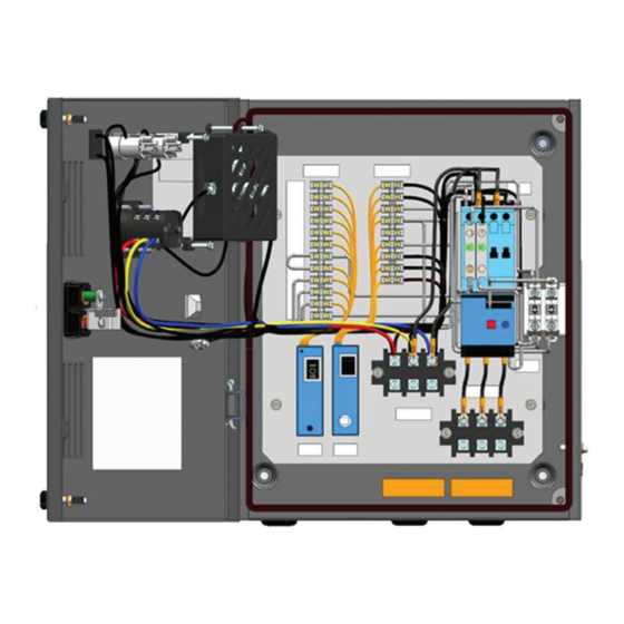
Installation, Maintenance & Troubleshooting guide | Version 04 Direct On Line Controller with WLC 4.1: Product description Fig. 9: DOL Controller with WLC 1. ‘ON’ push button (green) 2. ‘OFF/RESET’ push button (red) 3. Door knob 4. Metal Enclosure 5. Door 6. - Page 4 Installation, Maintenance & Troubleshooting guide | Version 04 Inside view of Direct On Line Controller with WLC 11 12 1: Amber LED 9: Thermal Overload Relay 2: Green LED 10: Starter Operating Modes 3: Rocker Switch 11: Line monitoring relay 4: Phase Selector switch 12: Water Level Controller 5: ON push button...
-
Page 5: Wiring Diagram
Installation, Maintenance & Troubleshooting guide | Version 04 4.2: Wiring Diagram: DOL Controller with WLC... - Page 6 Installation, Maintenance & Troubleshooting guide | Version 04 4.21 Control logic diagram...
- Page 7 Installation, Maintenance & Troubleshooting guide | Version 04 4.22 Power circuit diagram...
-
Page 8: Technical Details
Table: 20 Technical details of DOL Controller with WLC Recommended Max. Back-up Max. Line (HP / Range HRC Fuse rating, Recommended Type Contactor Relay Monitoring SIEMENS Make Cu cable size Relay type 3NA7 (sq:mm) – 500V* 3TE7131-1HC14-1Axx 3 / 2.2 3TS3010-0Axx-08K 3US5000-1H8K 7UG0613-0yy20 20A/500V 3TE7131-1KC16-1Axx 5 / 3.7... - Page 9 Installation, Maintenance & Troubleshooting guide | Version 04 Diagrammatic representation of the 3x modes of WLCA: Delivery mode Suction mode Dual Tank mode Fig.11 For Delivery mode to become operational: P2, P3 Sensor should be out of water For Suction mode to become operational: P1, P2, P3 Sensor should be inside water For Dual tank mode to become operational: P1,P2, P3 Sensor should be inside water &...
-
Page 10: Installation
& Rocker switch. • If the relay trips even when set at rated motor current the suitability of the starter/relay for the particular application should be checked with the nearest Siemens office. Operating Characteristics: The given characteristics (Fig. 6) are average values of all ranges and sizes of bimetal relays and are mainly intended to indicate the inverse time current characteristics &... - Page 11 Installation, Maintenance & Troubleshooting guide | Version 04 Operation: • Ensure the door is closed. • Rotate the Latch away from OFF push button • Switch On the rocker switch. • Check the status of amber LED. Wait till amber LED is continuously ON then only proceed. •...
-
Page 12: Operating Procedure In Normal Condition
Installation, Maintenance & Troubleshooting guide | Version 04 4.5: Operating procedure in normal condition Table: 21 DOL Controller with WLC operating sequence in normal condition Amber LMR-A WLCA 3 main Rocker LMR-A Amber ‘ON’ Push Starter Green Tank Mode Mode supply switch On-Delay... - Page 13 Installation, Maintenance & Troubleshooting guide | Version 04 Starter operation: LMR-A: Manual mode a. WLCA- Delivery mode 10A : Keep the LMR-A in Manual mode. 10B : Keep the WLC-A in Delivery mode. 10C : Switch ON 3-Phase incoming main supply. 10D : Turn ON the rocker switch 10E : Amber LED will start blinking for a period of min 0.5 min.
- Page 14 Installation, Maintenance & Troubleshooting guide | Version 04 LMR-A: Manual mode c. WLCA- Dual tank mode 10A : Keep the LMR-A in Manual mode. 10B : Keep the WLC-A in Dual tank mode. 10C : Switch ON 3-Phase incoming main supply. 10D : Turn ON rocker switch 10E : Amber LED will start blinking for a period of min 0.5 min.
- Page 15 Installation, Maintenance & Troubleshooting guide | Version 04 LMR-A: Auto mode b. WLCA- Suction mode 10A : Keep the LMR-A in Auto mode. 10B : Keep the WLC-A in suction mode. 10C : Switch ON the 3-Phase incoming main supply. 10D : Turn ON the rocker switch.
- Page 16 Installation, Maintenance & Troubleshooting guide | Version 04 LMR-A: Bypass mode a. WLCA- Delivery mode 10A : Keep the LMR-A in Bypass mode. 10B : Keep the WLC-A in Delivery mode. 10C : Switch ON the 3-Phase incoming main supply. (*Customer may switch ON the starter directly after switching ON the 3 phase incoming supply irresepctive of Blinking status as there is only indication for incoming supply faults and no Protection in Bypass mode).
- Page 17 Installation, Maintenance & Troubleshooting guide | Version 04 LMR-A: Bypass mode c. WLCA- Dual tank mode 10A : Keep the LMR-A in Bypass mode. 10B : Keep the WLC-A in Dual tank mode. 10C : Switch ON 3-Phase incoming main supply. (*Customer may switch ON the starter directly after switching ON the 3 phase incoming supply irresepctive of Blinking status as there is only indication for incoming supply faults and no Protection in Bypass mode).
-
Page 18: Troubleshooting Guidelines In Case Any Incoming Fault Is
Installation, Maintenance & Troubleshooting guide | Version 04 4.6: Troubleshooting Guidelines in case any incoming supply fault is present before switching ON the Starter Table: 22 DOL Controller + WLC operating sequence in fault condition Possible Corre- ‘ON’ Starter Tank LMR-A WLCA Rocker... - Page 19 Installation, Maintenance & Troubleshooting guide | Version 04 Starter Fault conditon: 1) LMR-A: Manual mode a. WLCA- Delivery mode 12A : Check the mode of LMR-A, if it is manual mode. 12B : Check the mode of WLC-A, if it is Delivery mode. 12C : Switches ON the 3-Phase incoming main supply.
- Page 20 Installation, Maintenance & Troubleshooting guide | Version 04 12J : Amber LED will remain ON continously indicating that the fault is cleared 12K : Press the Green ON push button to switch ON the starter. 12L : Starter gets switched ON. 12M: Green LED turns ON indicating that the starter is ON.
- Page 21 Installation, Maintenance & Troubleshooting guide | Version 04 4) LMR-A: Auto mode a. WLCA- Delivery mode : Check the mode of LMR-A, if it is Auto mode. : Check the mode of WLC-A, if it is Delivery mode. 12C to 12J : Follow steps from 12C to 12J of Manual &...
-
Page 22: Troubleshooting Guidelines In Fault Condition When Motor Stops While It Is In Running Condition
Installation, Maintenance & Troubleshooting guide | Version 04 4.7: Troubleshooting Guidelines in fault condition when motor stops while it is in running condition Table: 24 DOL Controller with WLC operating sequence in fault condition Motor LMR-A WLCA Amber Possible Corrective Amber ‘ON’... - Page 23 Installation, Maintenance & Troubleshooting guide | Version 04 Starter Fault conditon: 1. LMR-A: Manual mode a. WLCA- Delivery mode : Motor suddenly stops after running for some time. : Check the mode of LMR-A, if it is Manual mode. : Check the mode of WLCA, if it is Delivery mode. : Amber LED will start blinking 13E to 13J : Follow steps from 12E to 12J of LMR-A manual mode &...
- Page 24 Installation, Maintenance & Troubleshooting guide | Version 04 5. LMR-A: Auto mode b. WLCA- Suction mode : Motor suddenly stops after running for some time. : Check the mode of LMR-A, if it is Auto mode. : Check the mode of WLCA, if it is Suction mode. : Amber LED will start blinking 13E to 13J : Follow steps from 12H to 12M of LMR-A Auto mode &...
- Page 25 It helps our customers to thrive, communities to progress and supports sustainable development to protect our planet for the next generation. Creating environments that care. siemens.com/smart-infrastructure Published by Siemens Ltd Smart Infrastructure Electrical Products R&D Building, 48, Thane-Belapur Road Thane 400708, India Article no.