
Related Manuals for Honeywell Notifier FDU-80


Summary of Contents for Honeywell Notifier FDU-80
- Page 1 Remote Fire Annunciator FDU-80 Instruction Manual Document 51264 Rev: C2 4/24/2019 ECN: 18-305...
- Page 2 Fire Alarm & Emergency Communication System Limitations While a life safety system may lower insurance rates, it is not a substitute for life and property insurance! An automatic fire alarm system—typically made up of smoke Heat detectors do not sense particles of combustion and alarm detectors, heat detectors, manual pull stations, audible warning only when heat on their sensors increases at a predetermined rate devices, and a fire alarm control panel (FACP) with remote notifica-...
- Page 3 HARSH™, NIS™, and NOTI•FIRE•NET™ are all trademarks; and Acclimate® Plus™, eVance®, FlashScan®, FAAST Fire Alarm Aspiration Sensing Technology®, Honeywell®, Intelligent FAAST®, NOTIFIER®, ONYX®, ONYXWorks®, SWIFT®, VeriFire®, and VIEW® are all registered trademarks of Honeywell International Inc. Microsoft® and Windows® are registered trademarks of the Microsoft Corporation. Chrome™ and Google™ are trademarks of Google Inc. Firefox® is a registered trademark of The Mozilla Foundation.
- Page 4 • Your suggestion for how to correct/improve documentation Send email messages to: FireSystems.TechPubs@honeywell.com Please note this email address is for documentation feedback only. If you have any technical issues, please contact Technical Services. FDU-80 Instruction Manual — P/N 51264:C2 4/24/2019...
-
Page 5: Table Of Contents
Table of Contents Section 1: Overview ................................6 1.1: Introduction........................................6 1.2: UL 864 Compliance......................................6 1.2.1: UL 864 9th and 10th Edition ..................................6 1.2.2: Programming Features Subject to AHJ Approval ..........................6 1.3: Related Documentation .....................................6 Section 2: The FDU-80 Annunciator ..........................7 2.1: Compatible Panels ......................................7 2.2: Features of the FDU-80 .....................................7 2.3: Components ........................................8... -
Page 6: Section 1: Overview
Section 1: Overview 1.1 Introduction This document contains information for installing, programming, and operating the FDU-80 Remote Fire Annunciator. 1.2 UL 864 Compliance 1.2.1 UL 864 9th and 10th Edition • Per the UL Continuing Certification Program, UL 864 9th edition fire alarm control equipment will retain certification after the rollout of UL 10th edition (12/2/2018). -
Page 7: Section 2: The Fdu-80 Annunciator
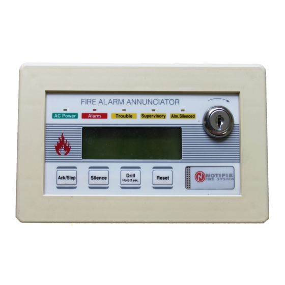
Section 2: The FDU-80 Annunciator The FDU-80 Annunciator is a compact, 80-character, backlit LCD fire annunciator designed for use with compatible FACPs (Fire Alarm Control Panels). The FDU-80 Annunciator display will mimic the FACP display. The FDU-80 is capable of displaying English-language text of system point status including device type, independent point alarm, trou- ble or supervisory, zone and custom alpha labels programmed into the control panel. -
Page 8: Components
The FDU-80 Annunciator Components 2.3 Components OFF = Key-switch Enabled ON = Piezo Enable Note: See “DIP Switch Settings OFF = Receive only Example” on page 9. Panel Configuration Top view Future use Piezo Sounder The FDU-80 sounder, if enabled, will be activated when any new Membrane Connector alarm or trouble is received from the panel. - Page 9 SW1 DIP Switch Settings The FDU-80 Annunciator Fire Alarm Control Panel SW1-4 SW1-5 SW1-6 Use This Setting for: NFS2-640, NFS-320, NFS-640 (all releases) AFP-300/400 (with FACP software Version 3.62 or higher) FireWarden2-100/FireWarden-100 (all releases) Future Use Future Use Future Use Future Use Future Use Future Use...
-
Page 10: Section 3: Operation
Section 3: Operation 3.1 Display Patterns The FDU-80 Annunciator directly displays (mimics) the information on the FACP display with the following exceptions: Upon Power-up, the FDU-80 may display the following message until a valid message is received from the FACP: INITIALIZING... -
Page 11: 5: Reset
LED Indicators Operation 3.2.5 Reset When the System Reset switch is pressed and released, the FDU-80 sends a Reset command to the control panel. This will turn off all control modules and Notification Appliance Circuits, temporarily turns off resettable power to 4-wire detectors, causes a 'System All Normal' message to be displayed on the FDU-80 and sends a 'System Reset' message to the FACP display, printer and FACP history files. -
Page 12: Section 4: Mounting
Section 4: Mounting 4.1 Annunciator Preparation The FDU-80 Annunciator can be surface mounted in a three-gang electrical box such as the P/N SBB-3 (2.75" depth) or semi-flush mounted in a three-gang electrical box, P/N 10103 or equivalent, with a minimum depth of 2.1875". The FDU-80 Annunciator can also be mounted in three gangable electrical switch boxes connected together. -
Page 13: 1: Mounting In Sbb-3 Three Gang Electrical Box
Semi-flush Mount Backbox Mounting 4.2.1 Mounting in SBB-3 Three Gang Electrical Box FDU-80 Remove the plug-in terminal blocks from the circuit board. Connect the EIA-485 and power wiring into the terminal block positions illustrated in Figure 5.1 on page 15 through Figure 5.5 on page 16. Plug the terminal blocks back into the P2 and P1 connectors on the back of the annunciator. -
Page 14: Surface Mount Backbox
Mounting Surface Mount Backbox 4.3 Surface Mount Backbox Remove the plug-in terminal blocks from the FDU-80 circuit board. Connect the EIA-485 and power wiring into the terminal block posi- tions illustrated in Figure 5.1 on page 15 through Figure 5.5 on page 16. Plug the terminal blocks back into the P2 and P1 connectors on the back of the annunciator circuit board. -
Page 15: Section 5: Electrical Connections
Section 5: Electrical Connections 5.1 Power Connections The FDU-80 Annunciator can be powered by the FACP (refer to the specific technical manual for the proper connection of the FDU-80) or from a remote UL listed, filtered power supply such as the FCPS-24S6/8. The power run to the annunciator must be power-limited but need not contain a power supervision relay since loss of power is inherently supervised through loss of communication with the annunci- ator. -
Page 16: Eia-485 Connections
Electrical Connections EIA-485 Connections FDU-80 Earth Ground Option no connection -24 VDC OUT +24 VDC OUT FCPS-24S6/8 Figure 5.3 Power Wiring to the FCPS-24S6/8 5.3 EIA-485 Connections EIA-485 connections are made to P1 on the FDU-80. All connections must be power-limited and supervised. Enable FACP communica- tion with the FDU-80 in the FACP programming if appropriate (refer to FACP manual). -
Page 17: Section 6: Eia-485 Shield Termination
Section 6: EIA-485 Shield Termination The EIA-485 circuit must be wired using a twisted, shielded pair cable with a characteristic impedance of 120 ohms (+/- 20%). Do not run cable adjacent to or in the same conduit as 120 VAC service, noisy electrical circuits that are powering mechanical bells or horns, audio circuits above 25 V , motor control circuits or SCR power circuits. -
Page 18: Shield In Full Conduit
EIA-485 Shield Termination Shield in Full Conduit 6.2 Shield in Full Conduit The EIA-485 line allows the FACP to communicate with the FDU-80 Annunciator. The shield for the EIA-485 line must be connected to earth ground at the FACP (both exiting and entering the FACP) but must be left floating (no connection) at the annunciator if it is the first or only device on the EIA-485 line. -
Page 19: Appendix A: Ul 864 8Th Edition Applications
Appendix A: UL 864 8th Edition Applications WARNING: AHJ APPROVAL THE NFS-640, AFP-300/400, AND FIREWARDEN NFW-100 HAVE NOT BEEN CERTIFIED TO COMPLY WITH THE REQUIREMENTS IN THE STANDARD FOR CONTROL UNITS AND ACCESSORIES FOR FIRE ALARM SYSTEMS, UL 864 9TH EDITION. OPERATION OF THESE PRODUCTS WITH PRODUCTS TESTED FOR UL 864 9TH EDITION HAS NOT BEEN EVALUATED. -
Page 20: A.2: Eia-485 Connections
UL 864 8th Edition Applications EIA-485 Connections FDU-80 Earth Ground Option no connection -24 VDC OUT +24 VDC OUT NFW-100 Figure A.3 Power Wiring to the NFW-100 A.2 EIA-485 Connections EIA-485 connections to the annunciator must be power-limited and supervised. A maximum distance of 6,000 feet (1829 m) @ 18 AWG (0.75mm ) twisted, shielded cable is allowed between the FACP and first FDU-80, between each FDU-80 and return to the FACP from the last FDU-80. - Page 21 EIA-485 Connections UL 864 8th Edition Applications FDU-80 - + + EIA-485 Out to Next Device EIA-485 Out to Next Device (or back to FACP) EIA-485 NFW-100 Figure A.6 EIA-485 Wiring to the NFW-100 FDU-80 Instruction Manual — P/N 51264:C2 4/24/2019...
-
Page 22: Index
Index Numerics FCPS-24S6/8 Power 16 receive/transmit ferrite core 16 see also communication 8 80-character 7 flange 13 reset switch 7 function switches 7 resound, piezo 7 see also switch functions 10 AC loss 7 acknowledge switch 7 SBB-3 backbox 12 Acknowledge/Step switch 7 grounding 12 semi-flush mounting 12... - Page 23 Manufacturer Warranties and Limitation of Liability Manufacturer Warranties. Subject to the limitations set forth herein, Manufacturer warrants that the Products manufactured by it in its Northford, Connecticut facility and sold by it to its authorized Distributors shall be free, under normal use and service, from defects in material and workmanship for a period of thirty six months (36) months from the date of manufacture (effective Jan.
- Page 24 NOTIFIER 12 Clintonville Road Northford, CT 06472-1610 USA 203-484-7161 www.notifier.com...