Table of Contents

Related Manuals for Honeywell FS10-R


Summary of Contents for Honeywell FS10-R
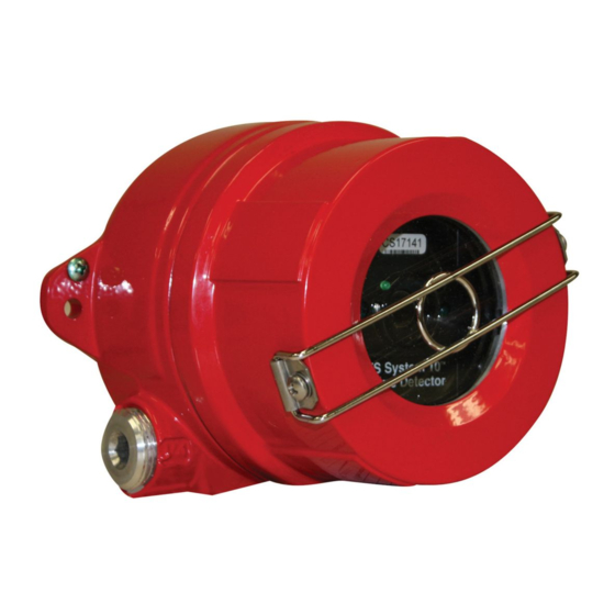
- Page 1 Installation Guide and Operating Manual Multi-Spectral Digital Infrared Electro-Optical Fire Detector Unitized, Two Stage, Quick Response FSC Model Nos. FS10-R & FS10-RN with Wide Band IR FS System 10 Digital Fire Detection/Process Control System...
-
Page 2: Notices And Trademarks
In no event is Honeywell liable to anyone for any indirect, special or consequential damages. The information and specifications in this document are subject to change without notice. - Page 3 OPERATOR MANUAL // NOTICES AND TRADEMARKS Other brand or product names are trademarks of their respective owners. Honeywell Analytics HONEYWELL...
-
Page 4: About This Document
About This Document Read and understand this manual before installing or operating equipment. No part of this document may be copied or reproduced without the express written permission of Honeywell Analytics. This manual is subject to change without notice. HONEYWELL... -
Page 5: Symbol Definitions
It may also be used to alert against unsafe practices. CAUTION: Symbol on the equipment refers the user to the product manual for additional information. The symbol appears next to required information in the manual. HONEYWELL... -
Page 6: Table Of Contents
Application ..................8 Responses ..................8 Input Power Requirements .............. 8 FirePic ..................8 No Silicone Used ................9 FS10-R, -RN Unitized Flame Detectors .......... 9 1.6.1 Alert / Early Warning Relay Output ....... 10 1.6.2 Alarm Relay Output ............10 1.6.3 Fault Relay Output ............ - Page 7 OPERATOR MANUAL // TABLE OF CONTENTS Index ..................... 25 Limited Warranty ................. 26 Contact Honeywell Analytics ............. 27 Americas ....................27 Europe ....................27 Asia Pacific ....................27 Internet ....................27 Telephone ....................27 HONEYWELL...
-
Page 8: Section 1: Introduction
-Diesel Generators -Internal Storage Tanks Responses The FS10-R type Detectors contain Alert / Fire Early Warning, Fire Alarm and Fault signal relays. The Alert/Fire Early Warning and Alarm relays are de-energized, and the Fault relay is energized during normal operation. If a fire occurs, a Fire Alarm is declared in less than 5.0 seconds. -
Page 9: No Silicone Used
: A PC computer is required to access FirePic. No Silicone Used silicone based sealant or silicone greases are used in the Flame Detector. FS10-R, -RN Unitized Flame Detectors The multi-spectral digital infrared Flame Detector, spanning the Wide Band IR , Near Band IR... -
Page 10: Alert / Early Warning Relay Output
Amp @ 24 VDC. The relay is energized during Normal Operation with closed contacts. When a Fault condition occurs, the relay is de-energized with opened contacts. Examples of Fault conditions include loss of power to the Detector or failure of the Self-Test feature. HONEYWELL... -
Page 11: Physical Description
If the Detector’s lens needs cleaning, the Detector’s LED blinks three times in a burst, every 10 seconds. 1.6.9 Warranty Honeywell Analytics warrants the Flame Detector against any defects in material and workmanship for a period of two (2) years from shipment date. HONEYWELL... -
Page 12: Section 2: Installation
The Detector may be mounted directly on the wall, or with the optional SM2 swivel mounting assembly or SM4 Stainless Steel Swivel Mount (refer to Section 6.1 for details). 1.50 4.38 ¾ NPT 2.40 0.67 2.09 1.10 4.66 Figure 3: Fire Detector Housing - Side View HONEYWELL... -
Page 13: Conduit Installation
1. If only one of the two ¾ inch NPT conduit openings of the Detector enclosure is used, appropriately seal the unused opening with a threaded, tapered plug. 2. In areas where moisture may accumulate, install an approved conduit trap or drain. HONEYWELL... -
Page 14: Power Supply Considerations
Power Connections. Refer to Section 1.3 for specific input power requirements and Table 2 and 3 for the appropriate pin assignments for the FS10-R and –RN Detector. Make certain the panel’s power supply can handle the load current of the total number Detectors connected to it. -
Page 15: Section 3: Operating Modes
• a problem has been encountered, such as a dirty Detector window. • failure in the wiring such as a severed cable, loose terminations. • the Detector’s internal self-checking reported a hardware failure. • power loss at the Detector. HONEYWELL... -
Page 16: Automatic Detector Test
Test Lamp, such as the Honeywell Analytics Model FS-846-B. Test the system “end-to-end” by activating each Detector separately. Note : It is recommended that the Honeywell Analytics Model FS- 846-B Portable Test Lamp is used to activate the Detectors individually. Advanced System Diagnostics The Detector’s FireBus... -
Page 17: Section 4: Maintenance And Replacement
Internal Detector Fault, such as a broken relay coil. If this persists, return the entire Detector to LED blinks 4 times Honeywell Analytics for service. See Section 4.3. Fault CONDITION (6) Internal Detector Fault, such as a memory failure. If this persists, return the entire Detector to LED blinks 6 times Honeywell Analytics for service. -
Page 18: Detector Module Replacement
6. Handle the Flame Detector Module with care and do not touch the sensor windows. 7. Carefully wrap the Module in static protection material (if none available, use aluminum foil) and ship to Honeywell Analytics. 8. To install a Detector Module, just reverse the removal steps listed above. -
Page 19: Section 5: Pinout Data
Alarm Relay Contact B (Normally OPEN) Alert / Early Warning Relay Contact A (Normally OPEN) Alert / Early Warning Relay Contact B (Normally OPEN) Table 2: Flame Detector Connector Pin-outs for FS10-R type Detectors J1 Connector: FIRE DETECTOR Module HONEYWELL... - Page 20 DO NOT CONNECT SHIELD AT THE FLAME DETECTOR. Note: COMM as it is used in this document is an abbreviation for Communications. Detector relays are shown as they are during Normal Operation, that is, there are no Fire Alarm conditions or Faults. HONEYWELL...
- Page 21 OPERATOR MANUAL // SECTION 5: PINOUT DATA 1 2 3 4 5 6 7 8 9 10 Figure 3: FS10-R, Detector Module, Connector Rear View HONEYWELL...
-
Page 22: Section 6: Accessories
OPERATOR MANUAL // SECTION 6: ACCESSORIES SECTION 6: ACCESSORIES Detector Heavy Duty Swivel Mount (Part No. SM2) 2.95 2.00 4.26 4.86 0.295 Dia. 4.7” approx. Figure 4: Detector Swivel Mount Figure 5: Model SM4 Stainless Steel Swivel Mount HONEYWELL... -
Page 23: Test Lamp (Part No. Fs-846)
: Refer to the SYSTEM TEST WARNING of Section 3.6. Disposable Protective Covers for Detectors (Part No. DPC-12) Honeywell Analytics’ Flame Detectors, with their unique wide spectral bands, can “see through” factory supplied Disposable Protective Covers with no reduction in Detector performance (for end-users with a planned maintenance schedule). -
Page 24: Pc Interface Kit (Part No. Fs10-Ik)
120 VAC wall transformer for recharging the battery, and User PC software. Note : The PC Interface Kit may also be used with a Detector that is powered by an external 24 VDC source (a complete user instruction is included with the Interface Kit). HONEYWELL... -
Page 25: Index
OPERATOR MANUAL // INDEX Index Controller Fault ....... 17 Input Power Detector Milliamps ........ 8 Cable ........19 Test Lamp ....... 23 Cleaning ......17 Through the Lens Fault ... 17 HONEYWELL... -
Page 26: Limited Warranty
Honeywell Analytics warrants its Products against defects in material and workmanship under normal use and service for a period of two (2) years from the date of shipment as described herein. Honeywell Analytics, at its option, will repair or replace, at no charge, such products found to be defective during the warranty period provided that they are returned in accordance with the terms of this warranty. -
Page 27: Contact Honeywell Analytics
Honeywell Analytics Asia Pacific Co., Ltd. #701 Kolon Science Valley (1) 43 Digital-Ro 34-Gil, Guro-Gu Seoul, 152-729 Korea Email: analytics.ap@honeywell.com Internet These Honeywell websites may be of interest to Industry Solution customers. Honeywell Organization Corporate www.honeywell.com Honeywell Analytics www.honeywellanalytics.com Telephone Contact us by telephone at these numbers. - Page 28 1998M0950 Revision A July 2014 © 2014 Honeywell International Inc.