Garmin 400W Series Instructions Manual
Continued airworthiness bell 407
Hide thumbs
Also See for 400W Series:
- Pilot's manual & reference (78 pages) ,
- Pilot's manual addendum (24 pages) ,
- Manual (22 pages)
Table of Contents
Advertisement
Quick Links
Instructions for Continued Airworthiness
Reg. No.____________
Rev.
Date
1
04/09/15
2
06/18/15
3
02/08/17
400W Series
Bell 407
Dwg. Number:
190-01226-14 Rev. 3
Garmin International, Inc.
1200 E. 151st Street
Olathe, Kansas 66062 USA
Record of Revision
Initial Release
Updated Airworthiness Limitations section
Updated troubleshooting table section to add GDL 88H and GTX 3X5
S/N_______________
Description of Change
Advertisement
Table of Contents

Related Manuals for Garmin 400W Series


Summary of Contents for Garmin 400W Series
- Page 1 400W Series Instructions for Continued Airworthiness Bell 407 Reg. No.____________ S/N_______________ Dwg. Number: 190-01226-14 Rev. 3 Garmin International, Inc. 1200 E. 151st Street Olathe, Kansas 66062 USA Record of Revision Rev. Date Description of Change 04/09/15 Initial Release 06/18/15 Updated Airworthiness Limitations section...
- Page 2 Company Proprietary Information This drawing and the specifications contained herein are the property of Garmin International or its subsidiaries and may not be reproduced or used in whole or in part as the basis for manufacture or sale of products without written permission.
-
Page 3: Table Of Contents
ICA Revision and Distribution ................26 2.16 Assistance......................26 2.17 Implementation and Record Keeping ..............26 AIRWORTHINESS LIMITATIONS ..................26 400W Series 190-01226-14 Rev. 3 Instructions for Continued Airworthiness Bell 407 Page 3 of 26... -
Page 4: Introduction
1.4 Permission to Use Certain Documents Permission is granted to any corporation or person applying for approval of a Garmin Model 400W series to use and reference appropriate STC documents to accomplish the Instructions for Continued Airworthiness and show compliance with STC engineering data. -
Page 5: Instructions For Continued Airworthiness
2.1 Introduction Content, Scope, Purpose and Arrangement: This document identifies the Instructions for Continued Airworthiness for the modification of the rotorcraft by installation of a 400W series GPS/WAAS Nav/Com unit under the Garmin Bell 400W/500W HTAWS STC SR02080SE. Applicability: Applies to Bell models 407 rotorcraft altered by... -
Page 6: Description Of Alteration
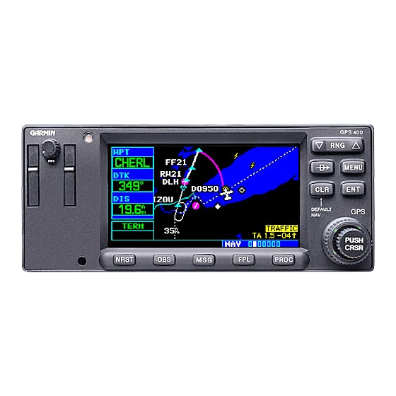
This STC upgrades existing avionics for the Bell 407 rotorcraft as summarized below. The Garmin Model 400W Series GPS/WAAS Nav/Com unit is a 6 ¼ inch wide unit mounted in the center console of the Bell 407. The 400W Series units combine a large number of easily accessible controls to use the color multi-function display, Nav and Com transceiver, GPS/WAAS navigator in a single unit. - Page 7 This STC also provides the data for installation of optional remote HTAWS annunciators and optional cyclic stick switches for remote control of COM and HTAWS functions. The 400W Series unit can interface to the Garmin G500H system GDU 620 PFD/MFD for display of navigation information and HTAWS annunciation.
- Page 8 2 4 MS51957‐37 SCREW, MACHINE, PAN HEAD, CROSS‐RECESSED, CRES, 0.1380‐32UNC‐2A 1 3 011‐02558‐00 LOUVER, ROUND, SCREENED, 3‐INCH, BLACK, FAA‐PMA GARMIN 1 2 190‐01226‐10‐01 BRACKET, COOLING FAN 1 1 013‐00103‐00 AVIONICS COOLING FAN WITH FAULT DETECTION GARMIN QTY. ITEM NO. PART NUMBER DESCRIPTION SUPPLIER 400W Series 190-01226-14 Rev. 3 Instructions for Continued Airworthiness Bell 407 Page 8 of 26...
- Page 9 5. 400W SERIES UNIT: FS40 Access or remove by using a 3/32 allen head screwdriver to loosen the locking mechanism through the access hole on the front of the unit. Note: location may vary slightly depending whether or not a dual navigator system is installed.
- Page 10 2.2.1 Weight and Balance Information 400W Series 190-01226-14 Rev. 3 Instructions for Continued Airworthiness Bell 407 Page 10 of 26...
-
Page 11: Control, Operating Information
The moment arms to the left side (looking forward) are negative (-) and the moment arms to the right side are positive (+). [4] Location of the 400W Series unit and GPS antenna may vary slightly depending whether or not a dual navigator system is installed. -
Page 12: Periodic Maintenance Instructions
2.5 Periodic Maintenance Instructions The 400W Series units are designed to detect internal failure. A thorough self-test is executed automatically upon application of power to the units, and built-in test is continuously executed. Detected errors are indicated on the equipment via failure annunciations. - Page 13 The display backlight lamp is rated by the manufacturer as having a usable life of 20,000 hours. This life may be more or less than the rated time depending on the operating conditions of the 400W Series unit. Over time, the backlight lamp may dim and the display may not perform as well in direct sunlight 400W Series 190-01226-14 Rev.
-
Page 14: Troubleshooting Information
Contact the Garmin factory repair station when the backlight lamp requires service. 2.5.3 Battery Replacement The 400W series has an internal keep-alive battery that will last about 10 years. The battery is used for GPS system information. Regular planned replacement is not necessary. The 400W series will display a ‘low battery’... - Page 15 Incompatible resolver or improper OBS Resolver won’t Check the resolver specifications and calibrate. connection. wiring. 400W Series unit resolver input not OBS indication on Check wiring and calibration. calibrated correctly. 400W Series unit Resolver has not been calibrated.
- Page 16 Problem Possible Cause Solution 400W Series unit RS-232 port not Check RS-232 port setting for port that RS-232 device is not configured correctly. device is connected to. communicating with Improper setup on the remote Verify the configuration of the other 400W/420W/430W.
- Page 17 2.6.1 400W Series Alerts The 400W Series will display a number of alerts. These are listed in the following table. Table 3. 400W Series Alert Troubleshooting Guide Alert Text Possible Cause Solution The ADS-B traffic system may have Check the applicable ADS-B...
- Page 18 CDI key disabled on the MAIN CDI/OBS CONFIG CONFIG page and deselect page. “Ignore CDI key” The 400W Series unit has detected Check for adequate ventilation Check unit cooling excessive display backlighting or check cooling airflow. Refer to temperature.
- Page 19 Data transfer error, please re-transmit unit crossfill of user data (user attempted. waypoints and/or flight plans). The 400W Series unit has detected a Contact Garmin technical Display backlight failure failure in the display backlighting. support. The 400W Series unit is in Demo ...
- Page 20 GPS receiver has failed. Operational status of the GPS receiver is unknown. The 400W Series unit has detected a Contact Garmin technical GPS needs service failure in its GPS receiver. support. The protocol version or database ...
- Page 21 Refer to Table 2: “The 400W determine its position. Series unit does not compute a position.” The 400W Series unit has detected a The data is not usable. Try Obstacle database integrity error problem with a database on the reloading the information onto Terrain data card.
- Page 22 Contact Garmin technical changed since it was last turned on in normal mode. support The 400W Series unit has detected a Reloading the information onto Terrain database integrity error problem with a database on the the card.
-
Page 23: Removal And Installation Information
New, Repaired or Exchange 400W Series is Installed If the 400W Series unit is removed for repair and reinstalled, or if the 400W unit is removed and replaced with a different 400W Series unit, then verify the correct software versions are on the 400W Series unit as specified in the Equipment List 400W/500W Series Installation Bell 407 STC listed in paragraph 2.1 of... -
Page 24: Diagrams
Installation drawing Bell 407, listed in Section 2.1 of this document Point to point wiring diagrams are in the Appendix of the 400W Rotorcraft STC Installation Manual. Refer to the GNS 400W Series Post- Installation Checkout Log retained in the rotorcraft permanent records for a list of the interfaced equipment and port configurations. -
Page 25: Special Inspection Requirements
The system does not require overhaul at a specific time period. Power on self-test and continuous BIT will monitor the health of the 400W Series unit. If the unit indicates an internal failure, the unit may be removed and replaced. See troubleshooting section 2.6 contained in this document.