
Related Manuals for JDS Uniphase OTU-8000 (EOTU8000E)


Summary of Contents for JDS Uniphase OTU-8000 (EOTU8000E)
- Page 1 JDSU OTU-8000 (EOTU8000E) Optical Test Unit for ONMSi Rack-based optical test unit for RFTS (Remote Fiber Test System) User Manual...
- Page 3 JDSU OTU-8000 (EOTU8000E) Optical Test Unit for ONMSi Rack-based optical test unit for RFTS (Remote Fiber Test System) User Manual...
- Page 5 Notice Every effort was made to ensure that the information in this document was accurate at the time of printing. However, information is subject to change without notice, and JDSU reserves the right to provide an addendum to this document with information not available at the time that this document was created.
- Page 6 This product should not be disposed of as unsorted municipal waste and should be collected separately and disposed of according to your national regulations. In the European Union, all equipment purchased from JDSU after 2005-08-13 can be returned for disposal at the end of its useful life.
-
Page 7: Table Of Contents
Table of Contents About This Guide Purpose and scope Assumptions ..........xii Technical assistance . - Page 8 Table of Contents Chapter 2 OTU-8000 General Description Front Panel description LEDs description Chapter 3 Installation of the OTU-8000 Installation of the OTU-8000 into the rack Fixing the OTU into the rack ....... . . 22 Setting the plexi protector onto the OTU-8000 .
- Page 9 Table of Contents General display ..........48 Menu frame .
- Page 10 Table of Contents Index User Manual 7OTU80050/01...
- Page 11 About This Guide Topics discussed in this chapter are as follows: – “Purpose and scope” page xii – “Assumptions” page xii – “Technical assistance” page xii – “Recycling Information” page xiii – “Conventions” page xiii User Manual 7OTU80050/01...
-
Page 12: About This Guide
About This Guide Purpose and scope Purpose and scope The purpose of this guide is to help you successfully use the OTU-8000 features and capabilities. This guide includes task-based instructions that describe how to install, configure, use, and troubleshoot the OTU- 8000. -
Page 13: Recycling Information
About This Guide Recycling Information Recycling Information JDSU recommends that customers dispose of their instruments and peripherals in an environnmentally sound manner. Potential methods include reuse of parts or whole products and recycling of products components, and/or materials. Waste Electrical and electronic Equipment (WEEE) Directive In the European Union, this label indicates that this product should not be disposed of with household waste. - Page 14 About This Guide Conventions Table 4 Symbol conventions This symbol represents a general hazard. This symbol represents a risk of electrical shock. NOTE This symbol represents a Note indicating related information or tip. This symbol, located on the equipment or its packaging, indicates that the equip- ment must not be disposed of in a land-fill site or as municipal waste, and should be disposed of according to your national regulations.
- Page 15 Prerequisites and delivery of Chapter 1 the OTU-8000 This chapter describes the prerequisites useful before installing/config- uring the OTU-8000. It also gives a detailed description of all the elements you will receive according to the configuration asked during the order. Topics discussed in this chapter are as follows: –...
-
Page 16: Prerequisites And Delivery Of The Otu-8000
Chapter 1 Prerequisites and delivery of the OTU-8000 Prerequisites of the OTU-8000 Prerequisites of the OTU-8000 General view of the prerequisites Fig. 1 View of the prerequisites OTU-8000 and rack Specific conditions are required to install the OTU-8000 in a rack. There are different conditions according to the type of rack used and whether the OTU-8000 is delivered with a plexi protection cover or not. -
Page 17: Overall Dimensions Of The Otu-8000 In The Racks
Chapter 1 Prerequisites and delivery of the OTU-8000 Prerequisites of the OTU-8000 Overall dimensions of the OTU- Floor-space 8000 in the racks Milled screws are used 72.2 Fig. 2 Rack 21’’ (ETSI) Countersunk screws are used 21.2 Milled screws are used 32.2 Fig. -
Page 18: Otu-8000 Power Supply
Chapter 1 Prerequisites and delivery of the OTU-8000 Prerequisites of the OTU-8000 OTU-8000 Power Supply OTU-8000 Consumption Your local electrical installation must comply with the OTU-8000 power consumption: – DC Input: -36 to -60V – Power consumption: 35W Section of electric wires Electric wires plugging into the OTU-8000 must have a section inferior or equal to 1,5mm². -
Page 19: Gsm Option And Sim Card
Chapter 1 Prerequisites and delivery of the OTU-8000 Delivery of the OTU-8000 GSM option and SIM card As an option, the OTU-8000 can be equipped with a GSM modem and send SMS notifications to a portable phone in case of alarms. The SMS notification in case of alarm is only used when the server is not reachable. -
Page 20: Elements Delivered On Option
Chapter 1 Prerequisites and delivery of the OTU-8000 Delivery of the OTU-8000 Plexi Supply connector Ferrite protector and ferrite Male Brackets ground connector Relay connector Kit for cover, supply cord and rack fixation Getting Started Manual Fig. 5 Delivery of the basic elements for OTU-8000 Elements delivered on option Once you received the OTU-8000, make sure that you have all the elements ordered, according to the configuration you ordered. -
Page 21: Gsm Option
Chapter 1 Prerequisites and delivery of the OTU-8000 Delivery of the OTU-8000 Indication of the brackets’ size Fig. 6 Brackets 19’’, 21’’ or 23’’ GSM Option With the GSM modem, an antenna is delivered. Fig. 7 GSM antenna AC/DC Power supply In order to use an AC power supply, the OTU-8000 is delivered with a converter, ended by the female connector. -
Page 22: Optical Switch Module
Chapter 1 Prerequisites and delivery of the OTU-8000 Delivery of the OTU-8000 Do not use any converter or power cord other than those supplied by JDSU as an option for the instrument. Optical Switch module The Optical Switch is already set into the OTU-8000, and the angled jumper with correct connector is also delivered. -
Page 23: Overall Dimensions Of The Osx8000 In The Racks
Chapter 1 Prerequisites and delivery of the OTU-8000 Delivery of the OTU-8000 Overall dimensions of the Floor-space OSX8000 in the racks Fig. 11 Rack 21’’ (ETSI) Fig. 12 Rack 19’’ User Manual 7OTU80050/01... -
Page 24: Launch Fiber Option
Chapter 1 Prerequisites and delivery of the OTU-8000 Delivery of the OTU-8000 Fig. 13 Rack 23’’ Launch Fiber Option The launch fiber module is delivered with 19’’ brackets mounted or it can be delivered with 21’’ or 23’’ brackets according to your order. The screws to fix the module into the rack are also delivered. -
Page 25: Summary Of The Delivery And The Prerequisites For An Otu-8000
Chapter 1 Prerequisites and delivery of the OTU-8000 Summary of the delivery and the prerequisites for an OTU-8000 OTDR plug-in set into the OTU-8000 (configuration with one OTDR). OTDR Manual Fig. 15 OTDR Module mounted + User Manual Summary of the delivery and the prerequisites for an OTU-8000 Reference Elements Prerequisite... -
Page 26: General Information On Warranty
Chapter 1 Prerequisites and delivery of the OTU-8000 General information on warranty Reference Elements Prerequisite • Kit to connect an OTU-8000 to an OSX8000 E98OTUXOSX – 1 cable OSX8000 <-> OTU-8000 (L= 35 • Kit to cascade OSX8000 E98OSXXOSX – 1 cable OSX8000 <-> OSX8000 (L= 20 •... - Page 27 Chapter 1 Prerequisites and delivery of the OTU-8000 General information on warranty JDSU performed repairs shall be warranted from defective material and workmanship for a period of ninety (90) days, or until the end of the Initial Warranty Period, whichever is longer. Risk of loss or damage to Product returned to JDSU for repair or replacement shall be borne by customer until delivery to JDSU.
- Page 28 Chapter 1 Prerequisites and delivery of the OTU-8000 General information on warranty User Manual 7OTU80050/01...
- Page 29 OTU-8000 General Chapter 2 Description This chapter gives a general view of the OTU-8000 elements. Topics discussed in this chapter are as follows: – “Front Panel description” page 16 – “LEDs description” page 18 User Manual 7OTU80050/01...
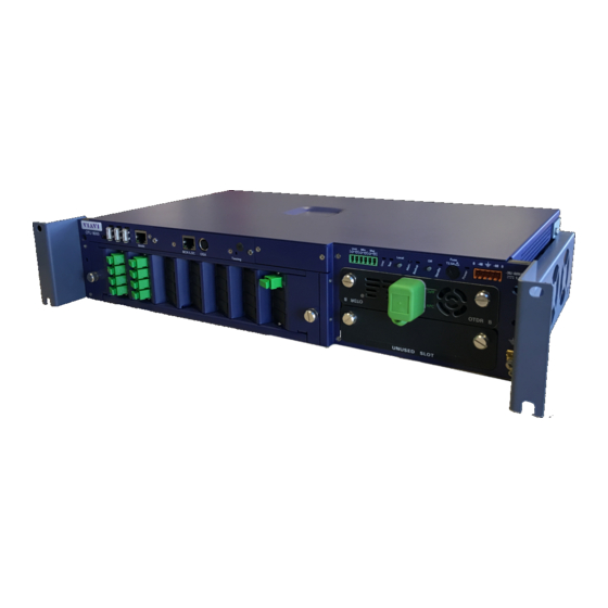
- Page 30 Chapter 2 OTU-8000 General Description Front Panel description Front Panel description All the connections of the OTU-8000 are located on the front panel. The following components are available: 11 12 Fig. 16 OTU-8000 Front panel Table 1 Connectors description USB ports (not used) RJ45 plug for the Ethernet interface Optical Switch module RJ45 plug for Ethernet backup or local...
- Page 31 Chapter 2 OTU-8000 General Description Front Panel description Table 1 Connectors description 2,5 A Fuse Up to 2 OTDR(s) may be plugged in at these places. DC power supply, which includes two redundant supply inputs -48 V DC male connector to connect the 5- pin connector Ground User Manual...
- Page 32 Chapter 2 OTU-8000 General Description LEDs description LEDs description The color of the leds and whether they are lit or not depends on the status of the OTU-8000. Fuse Server Local Fig. 17 LEDs description Table 2 Description of the leds status Symbol Value The led is solid red...
- Page 33 Chapter 2 OTU-8000 General Description LEDs description Table 3 Description of the device status Description The OTU-8000 is currently communicating with the server by the backup. BACKUP The latest communication or test by modem failed. The OTU-8000 software is stopped, The power can be unplugged.
- Page 34 Chapter 2 OTU-8000 General Description LEDs description User Manual 7OTU80050/01...
-
Page 35: Installation Of The Otu-8000
Installation of the OTU-8000 Chapter 3 This chapter describes the procedure to install successfully your OTU- 8000 and all the options available. It also explains how to connect and configure the OTU-8000 with the Web Interface. Topics discussed in this chapter are as follow: –... -
Page 36: Installation Of The Otu-8000 Into The Rack
Chapter 3 Installation of the OTU-8000 Installation of the OTU-8000 into the rack Installation of the OTU-8000 into the rack Check first, you have all the following elements: – the 19’’ brackets – the milled or countersunk screws according to the rack used and the presence or not of a door on the rack (see “OTU-8000 and rack”... -
Page 37: Setting The Plexi Protector Onto The Otu-8000
Chapter 3 Installation of the OTU-8000 Installation of the OTU-8000 into the rack Fig. 19 OTU-8000 and bracket Make the OTU-8000 slide to be sure it is correctly fixed. Setting the plexi protector The OTU-8000 is delivered with a plexi cover to protect the front side of onto the OTU-8000 the equipment into the rack. -
Page 38: Supply Installation
Chapter 3 Installation of the OTU-8000 Supply installation Supply installation The OTU-8000 can work with -48 V DC or AC. -48 V DC or AC Power Supply The OTU-8000 is manufactured to work on a power supply from -48V. You need to wire your -48 V power source to the female 5-point connector supplied with OTU-8000. -
Page 39: Installation Of The Female Ground Connector
Chapter 3 Installation of the OTU-8000 Supply installation NOTE The OTU-8000 cover panel clearly states the place of each wire to connect above the male connector. Installation of the Female The OTU-8000 is equipped with a male ground connector. You need a Ground Connector female clip (large: 6.3 mm / width: 0.8 mm), which will be set onto the Male Ground connector, as described in the photo below. -
Page 40: Installation For The Gsm Option
Chapter 3 Installation of the OTU-8000 Installation for the GSM Option Installation for the GSM Option NOTE The SIM card must be set into the OTU-8000 when the GSM option is available. Before installing the OTU-8000, and all the other options, you must install the SIM Data card into the slot provided for that purpose in the OTU-8000, if you acquired the GSM option. -
Page 41: Osx8000 Additional Optical Switch
Chapter 3 Installation of the OTU-8000 OSX8000 additional optical switch OSX8000 additional optical switch The number of available optical ports may be increased thanks to one or several OSX8000 . As seen in “Overall dimensions of the OTU-8000 in the racks” on page 3, this module is not integrated in the OTU. -
Page 42: Fixing The Osx8000 Into The Rack
Chapter 3 Installation of the OTU-8000 OSX8000 additional optical switch 4 Fix the brackets with the screws already used by the 19’’ brackets and use thread lock if necessary. Fixing the OSX8000 into the rack Once the correct brackets are set onto the OSX8000, you can install it into the rack. -
Page 43: Configurations Of 1 Otdr And 36 Ports
Chapter 3 Installation of the OTU-8000 OSX8000 additional optical switch Configurations of 1 OTDR The OSX8000 replaces the OTAU plug-in. In this case, a blank plate and 36 ports covers the place of the unnecessary module inside the OTU-8000. 1 Connect the OTDR plug-in to Common (on the OSX8000) with the supplied jumper. - Page 44 Chapter 3 Installation of the OTU-8000 OSX8000 additional optical switch OSX8000 OSX8000 Optical switch module Up to Optical switch module 30... Ports Ports 1...36 1...36 Optical Switch Optical switch module Fig. 32 Configuration > 1x36 (up to 30 x 36) NOTE The last OSX8000 is not always connected to the «n»...
-
Page 45: Installation Of The Launch Fiber Module
Chapter 3 Installation of the OTU-8000 Installation of the Launch Fiber Module Installation of the Launch Fiber Module The OTU-8000 can be equipped with a Launch Fiber Module, usually set above the OTU-8000. Fig. 34 Launch Fiber Module to place above the OTU-8000 NOTE This module is used to get default visibility at the very beginning of the... -
Page 46: Installation Of The Module Into The Rack
Chapter 3 Installation of the OTU-8000 Installation of the Launch Fiber Module 3 Unreel each extremity of the Launch fiber and set it into the notches. Notches for Launch Fiber Fig. 37 Launch Fiber set into notches 4 Close the Launch Fiber Module by screwing the 4 Torx screws on the upper cover. -
Page 47: Connecting The Launch Fiber Module
Chapter 3 Installation of the OTU-8000 Installation of the Launch Fiber Module 1 Set the Launch Fiber module into the rack, at the height wished 2 While one person is maintaining the module in position, the other one screws it onto the rack. Connecting the Launch Fiber You must use one launch fiber for each OTDR. -
Page 48: Description And Use Of The Relay Option
Chapter 3 Installation of the OTU-8000 Description and use of the Relay option NOTE You may connect either end of the same launch fiber to the OTDR. Description and use of the Relay option There are 3 relays, corresponding respectively to Unit alarm, major or critical optical alarm and minor optical alarm. -
Page 49: Otu-8000 Ip Configuration
Chapter 3 Installation of the OTU-8000 Configuring the OTU-8000 NOTE When the local session is finished, do not forget to press local again during 3s in order return to the normal mode. OTU-8000 IP configuration The OTU-8000 is setup in DHCP mode with a host name such as: otu- 8000e-xxxx (xxxx is the serial number) NOTE The serial number of the OTU-8000 can be found under the equip-... -
Page 50: Backup Route
Chapter 3 Installation of the OTU-8000 Configuring the OTU-8000 Backup route The backup route allows to configure an alternate route to be used when the main route is not available. It can be typically an IP route using internet as shown in the following figure: Fig. -
Page 51: Tab "Sms
Chapter 3 Installation of the OTU-8000 Configuring the OTU-8000 Tab «SMS» This tab shows the list of SMS recipients and if this option is enabled. These information are provided by ONMSi server. They cannot be modified by the user. Tab «Alert test» This tab has to be used to test the e-mail and sms. - Page 52 Chapter 3 Installation of the OTU-8000 Configuring the OTU-8000 OSX8000 in cascade Address 3 Address 2 Address 1 Command cable OSX <-> OSX (Kit E98OSXXOSX) Command cable OTU <-> OSX (Kit E98OTUXOSX) Fig. 46 Connection OTU-8000 <-> OSX8000 <-> OSX8000 2 Follow the instructions displayed on the screen: a Press Settings button onto the OSX8000 front panel The LED Addr.
- Page 53 Chapter 3 Installation of the OTU-8000 Configuring the OTU-8000 Confirmation of the OSX address modification Fig. 48 OSX address successfully changed 4 Press back the Settings button onto the OSX8000 to complete the configuration for the first OSX8000 5 Redo step 2 for all the OSX8000 to be configured.
- Page 54 Chapter 3 Installation of the OTU-8000 Configuring the OTU-8000 1 OSX8000 as distributor Address 2 Address 1 Address 31 Command cable OSX <-> OSX (Kit E98OSXXOSX) Command cable OTU <-> OSX (Kit E98OTUXOSX) Fig. 50 Connection OTU-8000 <-> OSX8000 <-> OSX8000 2 Connect all the others OSX8000 (see Figure 46 on page 38).
-
Page 55: Advanced Mode For A Single External Switch
Chapter 3 Installation of the OTU-8000 Configuring the OTU-8000 OSX distributor Fig. 51 Scan results with one OSX8000 set as distributor 12 Click on the Switch tab to apply the configuration (see “Configuring the optical switch” on page 43). Advanced mode for a single This command allows to connect one single OSX-8000 and the internal External Switch switch in two different ways:... -
Page 56: Adding Remote Optical Switch
Chapter 3 Installation of the OTU-8000 Configuring the OTU-8000 3 Click on Apply to validate the selected mode. Adding Remote Optical Switch Configuring the Remote Optical Switch 1 Follow the same instructions as for an OTU-8000, to configure the network information (see “OTU-8000 IP configuration”... -
Page 57: Configuring The Optical Switch
Chapter 3 Installation of the OTU-8000 Configuring the OTU-8000 Remote Optical Switch added Add a Remote Optical Switch Remove a Remote Optical Switch Fig. 55 Remote Switch successfully added In the remote switch web interface, check that in the window Admin >... - Page 58 Chapter 3 Installation of the OTU-8000 Configuring the OTU-8000 Click on the button A then to match the PPLY ETECTED WITCH registered configuration with the detected one. Once the detection is completed, the page is displayed as follows: OSX used as distributor Fig.
-
Page 59: Operating The Otu-8000
Operating the OTU-8000 Chapter 4 This chapter describes how to use the Web Interface provided with the OTU-8000. Topics discussed in this chapter are as follows: – “Introduction” on page 46 – “General display” on page 48 – “Exploitation” on page 49 –... -
Page 60: Introduction
Chapter 4 Operating the OTU-8000 Introduction Introduction Before using the web interface, make sure your OTU-8000 is correctly installed and either already configured to your LAN settings or started with the default procedure (see “OTU-8000 login” page 34 to see both cases). -
Page 61: User Profiles
Chapter 4 Operating the OTU-8000 Introduction User Profiles Two user profiles are defined. They have specific privileges: Profile Corresponding privileges USER The profile «User» allows to: – View (only) the OTU-8000 configuration – See the links – Display alarms – Perform a test or a measurement. –... -
Page 62: General Display
Chapter 4 Operating the OTU-8000 General display The Configuration page, with the Ethernet tab selected, is displayed by default. General display The OTU-8000 web interface is divided into two frames: – The left frame always displays a menu of different possible actions (see “Menu frame”... -
Page 63: Main Frame
Chapter 4 Operating the OTU-8000 Exploitation View/download the OTU-8000 logs in case of problems (see “Log files” on page 58 – Admin Change login, connection settings or disconnect users (see “Admin- istration” on page – Logout Disconnect from the web interface. The default welcome screen is displayed, ready to enter a new login. -
Page 64: Alarm Management
Chapter 4 Operating the OTU-8000 Exploitation Alarm Management The Web Interface allows to access the OTU-8000 to view the local alarm history and possibly carry out additional measurements. Alarm monitor Click on Alarm Monitor on the left menu to display the list of alarms detected by the OTU-8000 and not sent to the ONMSi. -
Page 65: Testing And Measuring A Fiber Under Alarm
Chapter 4 Operating the OTU-8000 Exploitation Major has been selected: Only major and critical alarms will be displayed (they appear in darker blue). Tested Fiber has been unchecked: Only unit and communication alarms will be displayed. Fig. 61 Filters area Testing and measuring a fiber under alarm Testing a fiber... -
Page 66: Otdr Links Status
Chapter 4 Operating the OTU-8000 Exploitation Fig. 62 Alarm details and trace displayed OTDR links status OTDR links can be tested or measured via the Web Interface 1 Click on OTDR Links on the left menu. The list of OTDR links is displayed. For each link, the date of the last test performed and the level of severity associated to the result are displayed. -
Page 67: Measuring An Otdr Link
Chapter 4 Operating the OTU-8000 Exploitation Fig. 64 List of possible tests for a link 5 Click on Start to perform the test 6 Once the test is completed, the trace is displayed. Fig. 65 Test result The status Available is displayed in the Configuration box. If the test or measurement has not been completed successfully, the status Failed is displayed and no trace is visible. - Page 68 Chapter 4 Operating the OTU-8000 Exploitation Auto Configuration Manual Configuration Fig. 66 Measurement parameters Measurement parameters are as follows: – OTDR type SM OTDR or MM OTDR – Acquisition Settings Auto Configuration / Manual Configuration – Wavelength From 1310 to 1625 nm 2, 3 –...
-
Page 69: Performing A Measurement On A Fiber
Chapter 4 Operating the OTU-8000 Exploitation Performing a measurement To perform a measurement on a fiber: on a fiber 1 Click on Measurement, in the left menu. 2 Configure the measurement parameters as seen in page 3 Click on Start to launch the measurement. -
Page 70: Functions Available With An Otdr Trace
Chapter 4 Operating the OTU-8000 Exploitation Example of configuration for measurement when OTU and Remote Optical Switches are used. Fig. 69 Example of configuration If a measurement must be performed from the OTU-8000 to the Optical Remote Switch 3 (dotted line Figure 69 page 56), configure the Optical Path as follows: Select OTU and Fig. - Page 71 Chapter 4 Operating the OTU-8000 Exploitation Zoom on trace The icons allow respectively to zoom in, zoom out and fit to content on the trace. Adding / Removing a trace Several OTDR traces can be displayed in overlay. To do so: 1 Click on the icon 2 Select the trace to be displayed in overlay with the current one 3 Click on OK to validate.
-
Page 72: Administration
Chapter 4 Operating the OTU-8000 Administration 2 Select / deselect the elements to be displayed / hidden. 3 Click on A to validate PPLY Administration This chapter provides details regarding the menu options: – Supervision – Logs – Admin NOTE These options require specific profiles for complete operation. -
Page 73: Degraded Mode
Chapter 4 Operating the OTU-8000 Administration Fig. 72 Log page 2 Select the log files you want to load: – either an archive with all the log files clicking on D OWNLOAD SHOT – or a specific log file, selecting it on the upper part of the page and clicking on D OWNLOAD SELECTED FILE Degraded mode... -
Page 74: Changing Settings
Chapter 4 Operating the OTU-8000 Administration Fig. 74 Changing login Changing settings All users may change their own session settings. NOTE It is not possible to change the settings of another user 1 Click on the tab Settings 2 Modify the following parameters if necessary: –... - Page 75 Chapter 4 Operating the OTU-8000 Administration 1 In the Admin Menu, click on the Tab Connected Users. The list of all connected users appears. 2 If you wish to disconnect someone, find the user in the list and click on the blue cross left to the login name. Fig.
- Page 76 Chapter 4 Operating the OTU-8000 Administration User Manual 7OTU80050/01...
-
Page 77: Technical Specifications
Technical Specifications Chapter 5 This chapter describes the technical specifications of the OTU-8000. Topics discussed in this chapter are as follows: – “Base Unit Technical specifications” on page 64 – “OTDR Modules technical specifications” on page 65 – “Optical switch technical specifications” on page 68 User Manual 7OTU80050/01... -
Page 78: Base Unit Technical Specifications
Chapter 5 Technical Specifications Base Unit Technical specifications Base Unit Technical specifications Mechanical Height Width 19", 21"(ETSI) or 23" Depth 260mm (ETSI), 300mm (19" or 23") Weight 6.50 kg I/O Interfaces Universal 3 x USB 2.0 Host serial Interface 1 x Mini USB 2.0 device LAN Interface 2 RJ45 connectors for 10/100/1000 Mbit/s Ethernet GSM if equipped with GSM modem... -
Page 79: Storage
Chapter 5 Technical Specifications OTDR Modules technical specifications Storage Flash disk capacity: 4 gB or higher Relay contacts (Option) 3 relays corresponding respectively to Unit alarm, major optical alarm and minor optical alarm. Relay is closed in normal condition Nominal switching capacity 1A @ 30VDC, 0.5A@125VAC Conductor cross section max. -
Page 80: Otdr Size And Weight
Chapter 5 Technical Specifications OTDR Modules technical specifications 8100B OTDR Series 8100C OTDR Series 8100D OTDR Series Laser Classes - Class 1 EFDA21CFR§1040.10 40 dB 36 dB 42.5 dB 39.5 dB 35 dB 43 dB Min. IEC Dynamic Range 39 dB 34 dB 42.5 dB 37.5 dB... -
Page 81: Distance Ranges
Chapter 5 Technical Specifications OTDR Modules technical specifications Distance Ranges Ranges for OTDR Module B 10 ns 30 ns 100 ns 300 ns 1 μs 3 μs 10 μs 20 μs 5 ns 0.5 km 1 km 2 km 5 km 10 km 20 km 40 km... -
Page 82: Optical Switch Technical Specifications
Chapter 5 Technical Specifications Optical switch technical specifications Ranges for UHR modules 3 ns 30 ns 100 ns 300 ns 1 μs 3 μs 10 μs 20 μs 5 km 10 km 20 km 40 km 80 km 140 km 260 km 380 km Optical switch technical specifications... -
Page 83: Options And Accessories
Options and accessories Chapter 6 This chapter describes the OTU-8000 references, the modules, the options and the accessories references. Topics discussed in this chapter are as follows:: – “OTU-8000 references” page 70 User Manual 7OTU80050/01... -
Page 84: Otu-8000 References
Chapter 6 Options and accessories OTU-8000 references OTU-8000 references Main frame / System Designation References Component / Test Set OTU-8000 V2 base unit (48VDC-2U/19 inches) EOTU8000E Options Designation References GSM interface for alarm notification E98EGSM Relay for external alarm reporting device E98RELAYS 23 inches rack mounting kit for OTU-8000 E98RACK23... - Page 85 Chapter 6 Options and accessories OTU-8000 references OTDR Module B Reference OTDR Module B 1310/1550 nm wavelength with con- E8126B tinuous wave light source and built-in power meter. OTDR Module B with filtered 1650 nm Raman com- E81165B pensated for in-service testing OTDR Module C Reference OTDR Module C 1550 nm...
- Page 86 Chapter 6 Options and accessories OTU-8000 references User Manual 7OTU80050/01...
- Page 87 Index OSX8000 OTU-8000 Front panel Alarm details Fuse management Alert test Ground Ground connector Backup route Brackets Internal Optical Switch Configuration delivery optical switch references OSX8000 IP configuration OTDR IP test OTU-8000 Consumption Converter Java2 Degraded mode Dimensions Launch Fiber OSX8000 brackets OTU-8000...
- Page 88 Index Measure Rack fiber Relay OTDR links Remote Optical Switch configuration remove ONMSi technical specifications OTU configuration on RJ45 server Router OSX8000 advanced mode cascade configuration SIM Card configurations delivery SIM card extended mode floor-space installation multipexed mode multiplexer references TCP/IP Network OTDR Test...
- Page 90 Test and Measurement Regional Sales North America Latin America Asia Pacific EMEA www.jdsu.com Toll Free: 1 800 638 2049 Tel: +55 11 5503 3800 Tel: +852 2892 0990 Tel: +49 7121 86 2222 Tel: +1 240 404 2999 Fax:+55 11 5505 1598 Fax:+852 2892 0770 Fax:+49 7121 86 1222 Fax:+1 240 404 2195...
- Page 91 JDSU OTU-8000 (EOTU8000E) Unité de Test optique pour ONMSi Unité de Test Optique rackable pour RFTS (Remote Fiber Test System) Manuel Utilisateur...
- Page 93 JDSU OTU-8000 (EOTU8000E) Unité de Test Optique pour ONMSi Unité de Test Optique rackable pour RFTS (Remote Fiber Test System) Manuel Utilisateur...
- Page 95 Notice Tout a été fait pour que les renseignements fournis dans ce document soit justes lors de l’impression. Cependant, ces renseignements sont sujets à changement sans préavis et JDSU se réserve le droit de donner, dans un additif à ce document, les informations qui n’étaient pas disponibles lors de sa création.
- Page 96 Des instructions pour renvoyer l'équipement à jeter à JDSU peuvent être trouvées dans la section «Environnement’ du site de JDSU» www.jdsu.com. Si vous avez des questions au sujet de la mise au rebut de votre équipement, contactez l'équipe de gestion de programme WEEE de JDSU: WEEE.EMEA@jdsu.com Manuel d’Utilisation...
- Page 97 Table des Matières A propos de ce guide Objectif et contenu ........xii Exigences .
- Page 98 Table des Matières Éléments en option ........6 Option Baie .
- Page 99 Table des Matières OTU-8000 et Interface Web ......35 Se loguer à l’OTU-8000 ........35 Configuration IP de l’OTU .
- Page 100 Table des Matières Administration ......... . .60 Changer de Login .
-
Page 101: A Propos De Ce Guide
A propos de ce guide Les sujets traités dans ce chapitre sont: – “Objectif et contenu” page xii – “Exigences” page xii – “Assistance Technique” page xii – “Informations concernant le recyclage” page xiii – “Conventions” page xiii User Manual 7OTU80050/01... -
Page 102: Objectif Et Contenu
A propos de ce guide Objectif et contenu Objectif et contenu Ce guide a pour but de vous aider à exploiter avec succès les fonctions de l’OTU-8000. Il décrit les concepts de base permettant d’installer et d’utiliser ce produit de manière optimale. De plus, il donne une descrip- tion complète des garanties et des services JDSU, des consignes pour le dépannage, ainsi que des modalités et conditions de l’accord de licence. -
Page 103: Informations Concernant Le Recyclage
A propos de ce guide Informations concernant le recyclage Informations concernant le recyclage JDSU recommande à ses clients d’oeuvrer pour le respect de l’environ- nement lors de la mise au rebut de ses instruments et périphériques, notamment en mettant l’accent sur les méthodes permettant un recy- clage total ou partiel des composants usagés. - Page 104 A propos de ce guide Conventions Table 3 Conventions relatives au clavier et au menu Description Exemple Le signe plus + indique Appuyer sur Ctrl+s l’appui simultané sur des touches. La virgule indique l’appui Appuyer sur Alt+f,s consécutif sur des touches. Une parenthèse orientée Dans la barre de menu, appuyer sur indique le choix de sous-...
-
Page 105: Pré-Requis Et Livraison De L'otu-8000
Pré-requis et livraison de Chapitre 1 l’OTU-8000 Ce chapitre décrit les pré-requis indispensables avant l’installation/ configuration de l’OTU-8000. Il fournis également une description détaillée de tous les éléments que vous recevrez selon la configuration demandée à la commande. Les sujets traités dans ce chapitre sont: –... -
Page 106: Pré-Requis De L'otu-8000
Chapitre 1 Pré-requis et livraison de l’OTU-8000 Pré-requis de l’OTU-8000 Pré-requis de l’OTU-8000 Vue générale des pré-requis Fig. 1 Pré-requis OTU-8000 et baie Des conditions spécifiques sont requises pour installer l’OTU-8000 dans la baie. Les conditions d’installation sont différentes selon le type de baie utilisé... -
Page 107: Encombrement De L'otu-8000 Dans La Baie
Chapitre 1 Pré-requis et livraison de l’OTU-8000 Pré-requis de l’OTU-8000 Encombrement de l’OTU-8000 Encombrement dans la baie Des vis moletées sont utilisées 72.2 Fig. 2 Baie 21’’ (ETSI) Des vis à tête fraisée sont utilisées 21.2 Des vis moletées sont utilisées 32.2 Fig. -
Page 108: Alimentation De L'otu-8000
Chapitre 1 Pré-requis et livraison de l’OTU-8000 Pré-requis de l’OTU-8000 Alimentation de l’OTU-8000 Consommation de l’OTU-8000 Votre installation électrique locale doit respecter la puissance de l’OTU- 8000: – Entrée alimentation: -36 à -60V continu – Puissance: 35W Section des câbles électriques Les fils électriques connectés à... -
Page 109: Accès Réseau
Chapitre 1 Pré-requis et livraison de l’OTU-8000 Réception de l’OTU-8000 Accès Réseau Le câble utilisé pour connecter l’OTU-8000 à Ethernet est un câble Ethernet classique avec un connecteur RJ45. Ce câble n’est pas livré avec l’OTU-8000 Option GSM et carte SIM En option, l’OTU-8000 peut être équipé... -
Page 110: Éléments En Option
Chapitre 1 Pré-requis et livraison de l’OTU-8000 Réception de l’OTU-8000 Capot de Connecteur d’alimentation Ferrite protection avec ferrite Connecteur Équerre Terre Mâle Guide de prise en main (Anglais) Connecteur Relais Kit pour fixation capot, cordon d’alimentation et baie Fig. 5 Livraison des éléments de base de l’OTU-8000 Éléments en option Une fois l’OTU-8000 livré, assurez vous que toutes les options... -
Page 111: Option Gsm
Chapitre 1 Pré-requis et livraison de l’OTU-8000 Réception de l’OTU-8000 Indication sur la taille des équerres Fig. 6 Equerres pour baie 19’’, 21’’ ou 23’’ Option GSM Une antenne est livrée si l’option modem GSM est commandée. Fig. 7 Antenne GSM Alimentation AC/DC Pour pouvoir utiliser une alimentation AC, l’OTU-8000 est livré... -
Page 112: Module Commutateur Optique
Chapitre 1 Pré-requis et livraison de l’OTU-8000 Réception de l’OTU-8000 Ne pas utiliser de convertisseur ou de cordon secteur autres que ceux proposés en option par JDSU. Module Commutateur Optique Le Commutateur Optique est installé dans l’OTU-8000, et le jumper coudé... -
Page 113: Osx8000
Chapitre 1 Pré-requis et livraison de l’OTU-8000 Réception de l’OTU-8000 OSX8000 Câble de commande OTU-8000 <-> OSX8000 (L= 35 cm) Connection to Connexion à the OSX8000 l’OTU-8000 Câble de commande OSX8000 <-> OSX8000 (L= 20 cm) Equerres OSX pour baie 21’’ Jarretière OTU-8000 <->... - Page 114 Chapitre 1 Pré-requis et livraison de l’OTU-8000 Réception de l’OTU-8000 Fig. 12 Baie 19’’ Fig. 13 Baie 23’’ Manuel d’Utilisation 7OTU80050/01...
-
Page 115: Option Fibre Amorce
Chapitre 1 Pré-requis et livraison de l’OTU-8000 Réception de l’OTU-8000 Option Fibre Amorce Le module Fibre Amorce est livré avec les équerres 19’’ montées ou peut être livré avec les équerres 21’’ ou 23’’ selon votre commande. Les vis utilisées pour fixer le module dans la baie sont également livrées. NOTE Utiliser un tournevis POZI N°2 et du frein filet. -
Page 116: Récapitulatif Des Éléments Livrés Et Des Pré-Requis Pour Un Otu-8000
Chapitre 1 Pré-requis et livraison de l’OTU-8000 Récapitulatif des éléments livrés et des pré-requis pour un OTU-8000 Récapitulatif des éléments livrés et des pré-requis pour un OTU-8000 Référence Éléments Pré-requis • Base OTU-8000 – Baie 19’’ • Équerres 19’’ – Tournevis POZI N°2 (pour fixer les équerres sur la baie) •... -
Page 117: Informations Sur La Garantie
Chapitre 1 Pré-requis et livraison de l’OTU-8000 Informations sur la Garantie Référence Éléments Pré-requis • Kit pour connecter des OSX8000 en cascade E98OSXXOSX – 1 câble OSX8000 <-> OSX8000 (L= 20 • Équerres 21’’ ou 23’’ E98OSXRKxx – Tournevis POZI N°1 & frein filet •... -
Page 118: Renonciation De La Garantie
Chapitre 1 Pré-requis et livraison de l’OTU-8000 Informations sur la Garantie ment, ou de qualité inférieur; ou (d) que les défauts étaient le résultat de dommages par le feu, l’explosion, un problème de puissance, ou tout acte de la nature. Les réparations réalisées par JDSU seront garanties sur la matière et la fabrication défectueuse pendant ue période de quatre-vingt dix (90) jours ou jusqu’à... -
Page 119: Description Générale De L'otu-8000
Description Générale de Chapitre 2 l’OTU-8000 Ce chapitre donne une vue générale du panneau avant de l’OTU-8000 et des LEDs. Les sujets traités dans ce chapitre sont les suivant: – “Description du panneau avant” page 16 – “Description des LEDs” page 18 Manuel d’Utilisation 7OTU80050/01... -
Page 120: Description Du Panneau Avant
Chapitre 2 Description Générale de l’OTU-8000 Description du panneau avant Description du panneau avant Toutes les connexions de l’OTU-8000 se font sur le panneau avant. Les composants suivants sont disponibles: 11 12 Fig. 16 Panneau avant OTU-8000 Table 1 Description des connecteurs Ports USB (non utilisés) Prise RJ45 pour l’interface Ethernet Module Commutateur Optique... - Page 121 Chapitre 2 Description Générale de l’OTU-8000 Description du panneau avant Table 1 Description des connecteurs Local bouton pour connecter un PC à l’ethernet défini en «local» Off bouton pour éteindre l’OTU8000 Fusible 2,5 A Jusqu’à 2 OTDRs peuvent être connectés. Alimentation DC, qui inclut deux entrées d’alimentation redondantes connecteur mâle -48 V DC pour connecter...
-
Page 122: Description Des Leds
Chapitre 2 Description Générale de l’OTU-8000 Description des LEDs Description des LEDs La couleur des leds et l’allumage ou non de celles-ci dépendent du statut de l’OTU-8000. Fuse Server Local Fig. 17 Description des LEDs Table 2 Description du statut des LEDs Symbole Valeur La LED est allumée en rouge fixe... - Page 123 Chapitre 2 Description Générale de l’OTU-8000 Description des LEDs Table 3 Description de l’état de l’appareil Description L’OTU-8000 est prêt à communiquer avec le serveur (ou est en train de communi- quer) via le LAN. MAIN La dernière tentative de communication avec le serveur via le LAN a échouée* L’OTU-8000 est en mode local L’OTU-8000 est en cours de communication...
- Page 124 Chapitre 2 Description Générale de l’OTU-8000 Description des LEDs Manuel d’Utilisation 7OTU80050/01...
-
Page 125: Installation De L'otu-8000
Installation de l’OTU-8000 Chapitre 3 Ce chapitre décrit la procédure pour installer avec succès l’OTU-8000 et toutes les options disponibles. Il explique également comment connecter et configurer l’OTU-8000 avec l’Interface Web. Les sujets traités dans ce chapitre sont: – “Installation de l’OTU-8000 dans la baie” page 22 –... -
Page 126: Installation De L'otu-8000 Dans La Baie
Chapitre 3 Installation de l’OTU-8000 Installation de l’OTU-8000 dans la baie Installation de l’OTU-8000 dans la baie Avant l’installation, vérifiez les éléments suivants: – les équerres 19’’ – les vis à tête fraisée ou les vis moletées selon la baie utilisée et la présence ou non de la porte sur la baie (voir “OTU-8000 et baie”... - Page 127 Chapitre 3 Installation de l’OTU-8000 Installation de l’OTU-8000 dans la baie Fig. 19 OTU-8000 avec les équerres 3 Faire glisser l’OTU-8000 pour s’assurer qu’il est correctement fixé. Installer le capot plexiglas L’OTU-8000 est livré avec le capot plexiglas pour protéger l’avant de l’appareil.
-
Page 128: Installation De L'alimentation
Chapitre 3 Installation de l’OTU-8000 Installation de l’alimentation Installation de l’alimentation L’OTU-8000 peut fonctionner avec du -48 V DC ou AC. Alimentation -48V DC ou AC L’OTU-8000 a été conçu pour fonctionner sur une alimentation à partir de -48 V. Vous devez brancher votre source -48 V au connecteur femelle 5-point fourni avec l’OTU-8000. -
Page 129: Installation Du Connecteur Terre Femelle
Chapitre 3 Installation de l’OTU-8000 Installation de l’alimentation NOTE Le panneau avant de l’OTU-8000 permet d’établir facilement la place de chaque fil à connecter au dessus du connecteur mâle. Installation du connecteur L’OTU-8000 est équipé d’un connecteur terre mâle. Vous devez avoir terre femelle un clip femelle (largeur: 6.3 mm / longueur: 0.8 mm), qui sera positionné... -
Page 130: Installation Pour L'option Gsm
Chapitre 3 Installation de l’OTU-8000 Installation pour l’option GSM Installation pour l’option GSM NOTE La carte SIM doit être installée dans l’OTU-8000 lorsque l’option GSM est disponible. Avant d’installer l’OTU-8000, et toutes les autres options, vous devez installer la carte SIM Data à l’emplacement prévu à cet effet dans l’OTU, si vous avez fait l’acquisition de l’option GSM. -
Page 131: Switch Optique Additionnel Osx8000
Chapitre 3 Installation de l’OTU-8000 Switch optique additionnel OSX8000 Switch optique additionnel OSX8000 Le nombre de ports optiques disponibles peut être augmenté en ajou- tant un ou plusieurs OSX8000 . Comme vu dans le chapitre “Encom- brement de l’OTU-8000 dans la baie” page 3, ce module n’est pas intégré... -
Page 132: Fixer L'osx8000 Dans La Baie
Chapitre 3 Installation de l’OTU-8000 Switch optique additionnel OSX8000 4 Fixer les équerres avec les vis déjà utilisées par les équerres 19’’ et utiliser du frein filet si nécessaire. Fixer l’OSX8000 dans la baie Une fois les équerres fixées sur l’OSX8000, vous pouvez installer celui- ci dans la baie. -
Page 133: Configuration Avec Un Switch Optique Interne Et Un Osx8000
Chapitre 3 Installation de l’OTU-8000 Switch optique additionnel OSX8000 Configurations d’un OTDR et L’OSX8000 remplace le Commutateur Optique. Dans ce cas, une 36 ports plaque vide couvre l’endroit du module inutilisé dans l’OTU-8000. 1 Connecter le tiroir OTDR au port Commun (sur l’OSX8000) avec le jumper fourni. -
Page 134: Configuration Avec Plus D'un Osx8000
Chapitre 3 Installation de l’OTU-8000 Switch optique additionnel OSX8000 OSX8000 OSX8000 Module Commutateur Module Commutateur Jusqu’à Optique Optique 30... Ports Ports 1...36 1...36 Switch optique Module Commutateur Optique Fig. 32 Configuration > 1x36 (jusqu’à 30 x 36) NOTE Le dernier OSX8000 n’est pas toujours connecté au «n» du switch interne (exemple: 3 OSX8000 connectés à... -
Page 135: Installation Du Module Fibre Amorce
Chapitre 3 Installation de l’OTU-8000 Installation du module Fibre Amorce Installation du module Fibre Amorce L’OTU-8000 peut être équipé d’un Module Fibre Amorce, le plus souvent situé au dessus de l’OTU-8000. Fig. 34 Module Fibre Amorce au dessus de l’ OTU-8000 NOTE Ce module est utilisé... -
Page 136: Installation Du Module Dans La Baie
Chapitre 3 Installation de l’OTU-8000 Installation du module Fibre Amorce Fixer les vis pour le Module Fibre Amorce Fig. 36 Installation de la Fibre Amorce 3 Dérouler chaque extrémité de la Fibre Amorce et les positionner dans les encoches. Encoche pour la Fibre Amorce Fig. -
Page 137: Fixer Le Module Fibre Amorce Dans La Baie
Chapitre 3 Installation de l’OTU-8000 Installation du module Fibre Amorce Fixer le Module Fibre Amorce Une fois que les bonnes équerres sont installées sur le module, vous dans la baie pouvez installer l’ensemble dans la baie. NOTE Garder les vis et rondelles près de la baie. 1 Mettre le Module Fibre Amorce dans la baie, à... -
Page 138: Description Et Utilisation De L'option Relais
Chapitre 3 Installation de l’OTU-8000 Description et utilisation de l’option Relais Si deux OTDRs sont utilisés, le Module Fibre Amorce est composé de 2 fibres amorces (un à gauche, un à droite) et offre 4 extrémités. Ces extrémités sont étiquetées L1 (Left 1), L2 (Left 2), R1 (Right 1) et R2 (Right 2). -
Page 139: Otu-8000 Et Interface Web
Chapitre 3 Installation de l’OTU-8000 OTU-8000 et Interface Web OTU-8000 et Interface Web Se loguer à l’OTU-8000 1 Connecter un PC (défini en DHCP pour obtenir une adresse IP automatiquement) à la prise RJ45 étiquetée Local, 2 Appuyer sur le bouton "Local" quelques secondes, jusqu’à ce que la LED Main s’allume. -
Page 140: Route De Backup
Chapitre 3 Installation de l’OTU-8000 OTU-8000 et Interface Web 1 Entrer ou modifier les informations nécessaires: – Nom d’hôte – Adresse IP – Masque de Sous réseau – IP de la Passerelle – Nom de Domaine – DNS Route de backup La route de backup permet de configurer une route alternative à... -
Page 141: Onglet "Sms
Chapitre 3 Installation de l’OTU-8000 OTU-8000 et Interface Web Si les deux serveurs sont configurés, il montre lequel est actuellement actif. Ces informations sont fournies par le serveur ONMSi. Elles ne peuvent pas être modifiées par l’utilisateur. Fig. 44 Configuration ONMSi Onglet «SMS»... - Page 142 Chapitre 3 Installation de l’OTU-8000 OTU-8000 et Interface Web – soit un OSX8000 est installé comme distributeur et les autres sont en cascade. OSX8000 en cascade 1 Connecter tous les OSX8000 qui peuvent être connecté à l’OTU avant d’effectuer la configuration. OSX8000 en Adresse Adresse...
- Page 143 Chapitre 3 Installation de l’OTU-8000 OTU-8000 et Interface Web 3 Une fois le processus terminé, et si l’adresse a été modifiée avec succès: – un texte affiché en vert confirme la modification d’adresse. – la LED Addr. clignote en vert sur l’OSX8000 Confirmation de la nouvelle adresse de l’OSX...
- Page 144 Chapitre 3 Installation de l’OTU-8000 OTU-8000 et Interface Web Configuration des OSX8000 avec un OSX8000 multiplexé Cette configuration doit être réalisé lorsqu’aucun OTAU n’est installé dans l’OTU-8000. 1 Connecter le premier OSX8000, qui sera utilisé comme distributeur par les autres, à l’OTU-8000 avec le câble de commande. 1 OSX8000 multiplexé...
-
Page 145: Mode Avancé Pour Un Seul Switch Externe
Chapitre 3 Installation de l’OTU-8000 OTU-8000 et Interface Web 11 Une fois le scan terminé, la boite de dialogue Détection s’affiche, avec pour chaque adresse OSX8000, son numéro de série et les données C/P. – l’OSX8000 Adresse 31, qui représente l’OSX8000 multiplexé, son numéro de série et les données C/P. -
Page 146: Ajouter Un Commutateur Optique Distant
Chapitre 3 Installation de l’OTU-8000 OTU-8000 et Interface Web En mode Étendu, le dernier port du switch interne est relié à l’OSX. Seul un seul OSX8000 est donc utilisable dans cette configuration, les autres ports du switch interne sont utilisés uniquement pour connecter des fibres à... -
Page 147: Configurer Le Commutateur Optique
Chapitre 3 Installation de l’OTU-8000 OTU-8000 et Interface Web Adresse IP ou nom d’hôte Fig. 54 Ajouter un Commutateur Distant 3 Cliquer sur A JOUTER 4 Cliquer sur OK dans la boîte de dialogue Confirmez l’ajout du commutateur... Une fois le processus fini, le commutateur distant, avec son adresse IP ou son nom, et le nombre de switchs, est affiché... - Page 148 Chapitre 3 Installation de l’OTU-8000 OTU-8000 et Interface Web Fig. 56 Configuration du commutateur lorsqu’un commutateur différent a été détecté Si les deux configurations ne correspondent pas , les différences sont affichées en rouge. Cliquer sur le bouton V puis sur pour ALIDER LE WITCH...
-
Page 149: Fonctionnement De L'otu-8000
Fonctionnement de l’OTU- Chapitre 4 8000 Ce chapitre décrit comment utiliser l’Interface Web fournie avec l’OTU- 8000. Les sujets traités dans ce chapitre sont: – “Introduction” page 46 – “Affichage Général” page 48 – “Exploitation” page 49 – “Administration” page 58 Manuel d’Utilisation 7OTU80050/01... -
Page 150: Introduction
Chapitre 4 Fonctionnement de l’OTU-8000 Introduction Introduction Avant d’utiliser l’interface web, assurez vous que l’OTU-8000 est correctement installé et qu’il est soit déjà configuré sur vos réglages LAN soit démarré avec la procédure par défaut (voir “Se loguer à l’OTU- 8000”... -
Page 151: Profils Utilisateur
Chapitre 4 Fonctionnement de l’OTU-8000 Introduction Profils utilisateur Deux profils utilisateur sont définis. Chacun a des privilèges spéci- fiques: Profil Privilèges USER Le profil «User» permet de: – Visualiser (uniquement) la configuration de l’OTU-8000 – Voir les liaisons – Afficher les alarmes –... -
Page 152: Affichage Général
Chapitre 4 Fonctionnement de l’OTU-8000 Affichage Général 2 Sélectionner la langue à utiliser dans la liste déroulante 3 Si nécessaire, cocher la case Break user log pour utiliser le même login qu’u autre utilisateur, simultanément. 4 Cliquer sur Submit. La page de Configuration, avec l’onglet Ethernet sélectionné, est affichée par défaut. -
Page 153: Cadre Principal
Chapitre 4 Fonctionnement de l’OTU-8000 Exploitation Demander une mesure (voir “Réaliser une mesure sur une fibre” page – Superviseur Tester les réponses IP (voir “Superviseur” page – Logs Visualiser/charger les logs OTU-8000 en cas de problèmes (voir “Fichiers Log” page 59 –... -
Page 154: Gestion Des Alarmes
Chapitre 4 Fonctionnement de l’OTU-8000 Exploitation NOTE Ces informations peuvent être visualisées par tous. Les tests et mesures peuvent également être réalisés par tous les utilisateurs. Gestion des alarmes L’Interface Web permet d’accéder à l’OTU-8000 pour visualiser l’histo- rique des alarmes locales et de réaliser des mesures additionnelles. Moniteur d’alarmes Cliquer sur Liste Alarmes à... -
Page 155: Tester Et Mesurer Une Fibre Sous Alarme
Chapitre 4 Fonctionnement de l’OTU-8000 Exploitation Décocher Unit, Fibre Testée et/ou Com dans la zone Filtres pour filtrer les alarmes selon leurs types. Sélectionner le niveau minimum de sévérité que vous souhaitez filtrer pour visualiser les alarmes selon leur niveau de sévérité. Vous pouvez visualiser quel filtre est appliqué... -
Page 156: Statut Des Liaisons Otdr
Chapitre 4 Fonctionnement de l’OTU-8000 Exploitation Fig. 62 Détails de l’alarme et courbe affichée Statut des liaisons OTDR Les liaisons OTDR peuvent être testées ou mesurées via l’Interface 1 Cliquer sur Liaisons OTDR à gauche de l’écran. La liste des liaisons OTDR est affichée. Pour chaque liaison, la date du dernier test réalisé... -
Page 157: Mesurer Une Liaison Otdr
Chapitre 4 Fonctionnement de l’OTU-8000 Exploitation Fig. 64 Liste des tests possibles pour une liaison 5 Cliquer sur Start pour réaliser le test 6 Une fois le test terminé, la courbe est affichée. Fig. 65 Résultat de Test Le statut Available est affiché dans le boîtier de configuration. Si le test ou la mesure n’a pas été... - Page 158 Chapitre 4 Fonctionnement de l’OTU-8000 Exploitation Configuration Manuelle Configuration Auto Fig. 66 Paramètres de mesure Les paramètres de mesure sont les suivants: – Type OTDR SM OTDR ou MM OTDR – Réglages Acquisition Configuration Auto / Configuration Manuelle – Longueur d’onde De 1310 à...
-
Page 159: Réaliser Une Mesure Sur Une Fibre
Chapitre 4 Fonctionnement de l’OTU-8000 Exploitation Réaliser une mesure sur une Pour réaliser une mesure sur une fibre: fibre 1 Cliquer sur Mesure, dans le menu de gauche. 2 Configurer les paramètres de mesure comme montré page 3 Cliquer sur Start pour lancer la mesure. - Page 160 Chapitre 4 Fonctionnement de l’OTU-8000 Exploitation Exemple de configuration pour une mesure avec un OTU et des Commutateurs Optiques Distants Fig. 69 Exemple de configuration Si une mesure doit être réalisée à partir de l’OTU-8000 jusqu’au Commutateur Distant n°3 (ligne en pointillé sur la Figure 69 page 56), configurer le Chemin optique comme suit: Sélectionner l’OTU et tous les Commutateurs Distants Fig.
- Page 161 Chapitre 4 Fonctionnement de l’OTU-8000 Exploitation Zoom sur la courbe Les icônes permettent respectivement d’agrandir une zone de la courbe, de dézoomer et d’afficher toute la courbe dans la fenêtre. Ajouter / Supprimer une courbe trace Plusieurs courbes OTDR peuvent être affichées en surimpression: 1 Cliquer sur l’icône 2 Sélectionner la courbe à...
-
Page 162: Administration
Chapitre 4 Fonctionnement de l’OTU-8000 Administration Aucune action sur la courbe (courbes en surimpression, position des curseurs etc.) ne sera enregistrée. Sélectionner les éléments à afficher sur la courbe 1 Cliquer sur l’icône , pour ouvrir une nouvelle fenêtre et pouvoir sélectionner les éléments qui seront visibles sur la courbe (résul- tats, curseurs etc.) 2 Sélectionner / dé... -
Page 163: Fichiers Log
Chapitre 4 Fonctionnement de l’OTU-8000 Administration 3 Sélectionner le port à utiliser via TCP/IP 4 Cliquer sur Exécuter Le résultat est affiché dans le bas du tableau. Fichiers Log Un utilisateur ayant le profil Install peut afficher les fichiers log générés. 1 Cliquer sur Logs dans le menu de gauche Fig. -
Page 164: Administration
Chapitre 4 Fonctionnement de l’OTU-8000 Administration Charger les fichier comme suggéré et essayer de redémarrer l’OTU- 8000. Si cette procédure ne résout pas le problème, nos services tech- niques peuvent vous demander le fichier log téléchargé. Administration Changer de Login Tous les utilisateurs peuvent changer leur propre login 1 Dans le menu Administration, sélectionner l’onglet Changer Login... -
Page 165: Utilisateurs Connectés - Déconnexion
Chapitre 4 Fonctionnement de l’OTU-8000 Administration Fig. 75 Modification des réglages NOTE Dans la page Paramètres, vous pouvez télécharger le Runtime Java2 pour afficher les courbes acquises via l’interface Web. Cliquer sur Téléchargement du runtime java2 pour le télécharger directe- ment sur PC ou cliquer sur Téléchargement du runtime java2 depuis internet pour ouvrir la page internet de téléchargement dans l’interface web. - Page 166 Chapitre 4 Fonctionnement de l’OTU-8000 Administration Manuel d’Utilisation 7OTU80050/01...
-
Page 167: Spécifications Techniques
Spécifications Techniques Chapitre 5 Ce chapitre fournit les spécifications techniques de l’OTU-8000. Les sujets traités dans ce chapitre sont: – “Spécifications techniques de la Base” page 64 – “Spécifications techniques des Modules OTDR” page 65 – “Spécifications techniques Commutateur Optique” page 68 Manuel d’Utilisation 7OTU80050/01... -
Page 168: Spécifications Techniques De La Base
Chapitre 5 Spécifications Techniques Spécifications techniques de la Base Spécifications techniques de la Base Mécanique Hauteur Largeur 19", 21"(ETSI) or 23" Profondeur 260mm (ETSI), 300mm (19" or 23") Poids 6.5 kg Interfaces E/S Interface 3 x USB 2.0 Host 1 x Mini USB 2.0 device Interface LAN 2 connecteurs RJ45 pour Ethernet 10/100/1000 Mbit/s GSM si l’OTU-8000 est equipée de l’option GSM... -
Page 169: Stockage
Chapitre 5 Spécifications Techniques Spécifications techniques des Modules OTDR Stockage Capacité Disque flash: 4 Go ou plus Contact Relais (Option) 3 relais correspondant chacun respectivement à l’alarme Unit, alarme optique majeure et alarme optique mineure. Le relais est fermé en condition normal. Capacité... -
Page 170: Poids Et Dimensions
Chapitre 5 Spécifications Techniques Spécifications techniques des Modules OTDR Modules Série 8100B OTDR Série 8100C OTDR Série 8100D OTDR Classes Laser - Classe 1 EFDA21CFR§1040.10 40 dB 36 dB 42.5 dB 39.5 dB 35 dB 43 dB Min. Dynamique IEC 39 dB 34 dB 42.5 dB... -
Page 171: Portées
Chapitre 5 Spécifications Techniques Spécifications techniques des Modules OTDR Portées Portées pour Modules B 10 ns 30 ns 100 ns 300 ns 1 μs 3 μs 10 μs 20 μs 5 ns 0.5 km 1 km 2 km 5 km 10 km 20 km 40 km... -
Page 172: Spécifications Techniques Commutateur Optique
Chapitre 5 Spécifications Techniques Spécifications techniques Commutateur Optique Portées pour Modules UHR 3 ns 30 ns 100 ns 300 ns 1 μs 3 μs 10 μs 20 μs 5 km 10 km 20 km 40 km 80 km 140 km 260 km 380 km Spécifications techniques Commutateur Optique... -
Page 173: Options Et Accessoires
Options et accessoires Chapitre 6 Ce chapitre fournis les références de l’OTU-8000, des modules, des options et des accessoires. Les sujets traités dans ce chapitre sont: – “Références OTU-8000” page 70 Manuel d’Utilisation 7OTU80050/01... -
Page 174: Références Otu-8000
Chapitre 6 Options et accessoires Références OTU-8000 Références OTU-8000 Unité centrale / Composant Désignation Référence Système / Test Base OTU 8000 V2 (48VDC-2U/19 pouces) EOTU8000E Options Désignation Références Interface GSM pour la notification des alarmes E98EGSM Relais pour rapport d’alarme externe E98RELAYS Kit de montage dans baie 23 pouces de l’OTU-8000 E98RACK23... -
Page 175: Modules Otdr
Chapitre 6 Options et accessoires Références OTU-8000 Modules OTDR Module UHR Référence Module OTDR Ultra Haute Résolution 1650 nm E8118RUHR65 Filtré Modules OTDR B Référence Module OTDR B 1310/1550 nm avec source continue E8126B et radiomètre intégrés. Module OTDR B avec 1650 nm filtré et compensé E81165B Raman. - Page 176 Chapitre 6 Options et accessoires Références OTU-8000 Manuel d’Utilisation 7OTU80050/01...
-
Page 177: Index
Index commutateur distant OSX8000 Adaptateur OTDR OTU-8000 Alarmes Configuration IP détails gestion Connecteur terre Alimentation Consommation adaptateur Courbe Arrêt session ajouter/supprimer autre fenêtre curseurs sauvegarder Baie tableau de résultats Brochage zoom Capot plexiglas Dimensions Carte SIM OSX8000 Commutateur distant OTU-8000 ajouter Disque flash configuration... - Page 178 Index équerres mode avancé installation mode étendu livraison mode multiplexé multiplexé Fibre amorce OTDR configurations configuration Fichiers Log livraison Fusible OTU-8000 allumer éteindre réglages session spécifications Jarretières Java2 Pré-requis LEDs Relais Liaisons OTDR Réseau TCP/IP mesure RJ45 test Route de backup Login Routeur login...
- Page 180 Test and Measurement Regional Sales North America Latin America Asia Pacific EMEA www.jdsu.com Toll Free: 1 800 638 2049 Tel: +55 11 5503 3800 Tel: +852 2892 0990 Tel: +49 7121 86 2222 Tel: +1 240 404 2999 Fax:+55 11 5505 1598 Fax:+852 2892 0770 Fax:+49 7121 86 1222 Fax:+1 240 404 2195...