JDS Uniphase hst-3000 User Manual
Ethernet tester
Hide thumbs
Also See for hst-3000:
- User manual (236 pages) ,
- Testing manual (24 pages) ,
- Instruction manual (14 pages)
Table of Contents
Advertisement
Quick Links
Advertisement
Table of Contents
Troubleshooting

Related Manuals for JDS Uniphase hst-3000


Summary of Contents for JDS Uniphase hst-3000
- Page 1 HST-3000 Ethernet Testing User’s Guide...
- Page 3 HST-3000 Ethernet Testing User’s Guide Communications Test and Measurement Solutions One Milestone Center Court Germantown, Maryland 20876-7100 USA Toll Free 1-855-ASK-JDSU Tel +1-240-404-2999 Fax +1-240-404-2195 www.jdsu.com...
- Page 4 Copyright release Reproduction and distribution of this guide is authorized for Government purposes only. Trademarks JDS Uniphase, JDSU, HST-3000, and HST-3000C are trade- marks or registered trademarks of JDS Uniphase Corporation in the United States and/or other countries.
- Page 5 In order to maintain compliance with the limits of a Class B digital device JDSU requires that quality interface cables be used when connecting to this equipment. Any changes or modifications not expressly approved by JDSU could void the user's authority to operate the equipment. HST-3000 Ethernet Testing User’s Guide...
- Page 6 Instructions for returning waste equipment and batteries to JDSU can be found in the Environmental section of JDSU’s web site at www.jdsu.com. If you have questions concerning disposal of your equipment or batteries, contact JDSU’s WEEE Program Management team at WEEE.EMEA@jdsu.com. HST-3000 Ethernet Testing User’s Guide...
-
Page 7: Table Of Contents
HST-3000 Ethernet Testing User’s Guide ... xvi HST-3000 Base Unit User’s Guide ....xvi Safety and compliance information . - Page 8 Clearing history results ......40 Instrument settings and user preferences ... 40 HST-3000 Ethernet Testing User’s Guide...
- Page 9 Using the automatic loopback feature... . . 89 Monitoring Ethernet traffic ..... . . 93 HST-3000 Ethernet Testing User’s Guide...
- Page 10 Configuring the traffic load ..... 141 Filtering received traffic using layer 2 criteria ..142 viii HST-3000 Ethernet Testing User’s Guide...
- Page 11 About multiple streams testing ....182 Selecting a multiple streams test....182 HST-3000 Ethernet Testing User’s Guide...
- Page 12 Navigating through the test ....209 Running the test ......210 HST-3000 Ethernet Testing User’s Guide...
- Page 13 1G Pair Status result ......264 Polarity result ......265 HST-3000 Ethernet Testing User’s Guide...
- Page 14 SFP specifications ......315 Environmental specifications ....316 Glossary Index HST-3000 Ethernet Testing User’s Guide...
-
Page 15: About This Guide
“Purpose and scope” on page xiv – “Assumptions” on page xiv – “Terminology” on page xiv – “HST-3000 Ethernet Testing User’s Guide” on page xvi – “HST-3000 Base Unit User’s Guide” on page xvi – “Safety and compliance information” on page xvi –... -
Page 16: Purpose And Scope
Assumptions This guide is intended for novice, intermediate, and experi- enced users who want to use the HST-3000 with an Ethernet SIM efficiently and effectively. We assume that you have basic computer experience and are familiar with basic telecommu- nications safety, concepts, and terminology. - Page 17 3 IP traffic over a layer 2 Ethernet network. For definitions of other terms used in this guide, see “Glos- sary” on page 317. HST-3000 Ethernet Testing User’s Guide...
-
Page 18: Hst-3000 Ethernet Testing User's Guide
JDSU sales representative. This guide also contains specifications and contact informa- tion for JDSU’s Technical Assistance Center (TAC). This user’s guide should be used in conjunction with the HST-3000 Base Unit User’s Guide. HST-3000 Base Unit User’s Guide The HST-3000 Base Unit User’s Guide contains overall infor-... -
Page 19: Technical Assistance
Before you contact JDSU for technical assistance, please have the serial numbers for the service interface module (SIM) and the base unit handy (see “Locating the serial number” in the HST-3000 Base Unit User’s Guide). Table 1 Technical assistance centers... - Page 20 Slanted brackets < > group <password> required arguments. Table 3 Keyboard and menu conventions Description Example A plus sign + indicates simul- Press Ctrl+s taneous keystrokes. A comma indicates consecu- Press Alt+f,s tive key strokes. xviii HST-3000 Ethernet Testing User’s Guide...
- Page 21 WARNING Indicates a potentially hazardous situation which, if not avoided, could result in death or serious injury. CAUTION Indicates a potentially hazardous situation which, if not avoided, may result in minor or moderate injury. HST-3000 Ethernet Testing User’s Guide...
-
Page 22: Hst-3000 Ethernet Testing User's Guide
About This Guide Conventions HST-3000 Ethernet Testing User’s Guide... -
Page 23: Getting Started
Getting Started Chapter 1 This chapter provides basic information about testing using the HST-3000 with an Ethernet SIM. Topics discussed in this chapter include the following: – “Overview” on page 2 – “Software options” on page 6 – “Status LEDs” on page 7 –... -
Page 24: Overview
Chapter 1 Getting Started Overview Overview Using an HST-3000 with an Ethernet SIM, you can perform the test operations necessary to install, maintain, and trouble- shoot Ethernet and IP service. The unit allows you to test connectivity, verify throughput, measure delay, and transmit patterns to stress the jitter and noise characteristics of network elements and systems. - Page 25 For additional details on the color display, see the HST-3000 Base Unit User’s Guide. – Q-in-Q support. You can configure, transmit, and analyze Q-in-Q encapsulated traffic.
-
Page 26: What's New
– Layer 2 transparency testing.You can transmit and analyze layer 2 traffic with headers (such as CDP, VTP, STP, and R/STP) to verify that a circuit can support a variety of control protocols irrespective of the transport HST-3000 Ethernet Testing User’s Guide... - Page 27 The test is initiated by a master tester on the near end. The master tester then automatically configures the slave tester on the far end. HST-3000 Ethernet Testing User’s Guide...
-
Page 28: Software Options
First Mile OAM communications. TCP/UDP Using this option, you can transmit HST3000-TCPUDP and analyze IPv4 layer 4 traffic with TCP or UDP headers in terminate mode. The IPv6 Traffic option is also required for layer 4 IPv6 testing. HST-3000 Ethernet Testing User’s Guide... -
Page 29: Status Leds
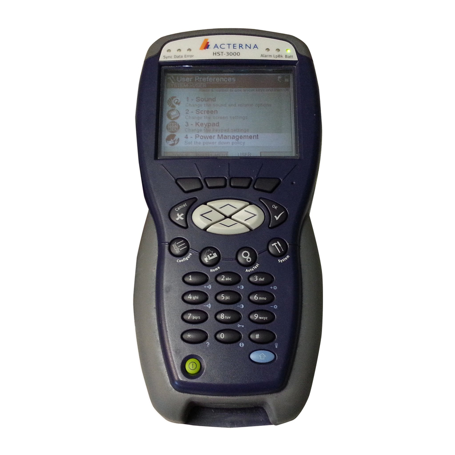
HST3000-MPLS to two MPLS labels for transmitted traffic when testing and qualifying core and metro networks. Status LEDs Six status LEDs are located on the front of the HST-3000, above the screen. Table 7 describes the status LEDs. Table 7... -
Page 30: Connectors
The Batt LED reports the battery status. NOTE: For information about charging the battery, changing batteries, and resetting the battery capac- ity indicator, see the HST-3000 Base Unit User’s Guide. In addition to the status LEDs, soft LEDs are provided in the LED result category. - Page 31 Ethernet SIM. Electrical RJ-45 Connectors Optical SFP connectors Figure 1 Ethernet interface connectors Table 8 describes the connectors on the Ethernet SIM. For additional input and output specifications, see Appendix HST-3000 Ethernet Testing User’s Guide...
-
Page 32: Test Applications
10/100/1000 Mbps inter- faces in monitor, thru, or terminate modes. For details, see the HST-3000 VoIP Testing User’s Guide. Test applications Terminate, monitor, and thru applications are provided when testing 10/100/1G electrical or 1G optical signals; terminate and monitor applications are available when testing 100M optical signals. -
Page 33: Application
HST. Analysis is restricted to the R/T 1 port. Figure 3 illustrates the signal path when running a terminate application for a 1G optical signal. Figure 3 Terminate application: 1G optical signal path HST-3000 Ethernet Testing User’s Guide... -
Page 34: Optical Ethernet Terminate Application
R/T 1 RJ-45 port. monitor application The HST does not pass the signal through to the transmitter, as it does in when running an electrical Thru application (see “10/100/1G Electrical Ethernet thru application” on page 15). HST-3000 Ethernet Testing User’s Guide... -
Page 35: Optical Ethernet Monitor Application
When monitoring 1G optical signals, the HST analyzes the Ethernet monitor received signal on the R/T 1 SFP port. application Figure 6 illustrates the signal path when monitoring 1G optical signals. Figure 6 Monitor application: 1G optical signal path HST-3000 Ethernet Testing User’s Guide... -
Page 36: Optical Ethernet Monitor Application
When running Thru applications for 10/100/1G electrical and 1G optical signals, the HST monitors the signal on the receiving port, and then passes it through to the opposite port’s transmitter. HST-3000 Ethernet Testing User’s Guide... -
Page 37: 10/100/1G Electrical Ethernet Thru Application
Figure 8 Thru application: electrical signal path 1G Optical Figure 9 illustrates the signal path when running Thru applica- Ethernet thru tions for 1G optical signals. application Figure 9 Thru application: 1G optical signal path HST-3000 Ethernet Testing User’s Guide... -
Page 38: Test Scenarios
For detailed test result descriptions, see Appendix Verifying In this scenario, you configure the HST to emulate service from customer equipment on the link, and then verify connec- connectivity tivity and evaluate latency on the circuit. and evaluating latency HST-3000 Ethernet Testing User’s Guide... - Page 39 If you are testing on a switched network, a second HST, or another JDSU Ethernet test set (such as the SmartClass Ethernet Tester, FST-2802, or MTS-8000 Transport Module) must be connected to the network at the far end, and a soft HST-3000 Ethernet Testing User’s Guide...
- Page 40 Terminate tests are typically performed after the loopback is established to verify connectivity, measure frame and packet loss, measure round trip delay (latency), and insert and observe errors. HST-3000 Ethernet Testing User’s Guide...
-
Page 41: Verifying Throughput And Stressing The Network
For example, you can configure traffic on a link the HST to display test results for all traffic carrying a specific BERT pattern in the payload, or for all traffic originating from a specific source address or VLAN. HST-3000 Ethernet Testing User’s Guide... - Page 42 Figure 13 Monitoring traffic using a splitter If you want to monitor full duplex 1 Gigabit Ethernet or elec- trical Ethernet traffic from both directions, you can use the two ports provided on the HST to pass traffic through your unit. HST-3000 Ethernet Testing User’s Guide...
-
Page 43: Using J-Connect To Discover Another Jdsu Test Set
Before you begin testing, you can automatically detect other JDSU test instruments on the same subnet and determine their capabilities.You can then optionally configure key param- eters for your test automatically based on a discovered instru- ment’s settings. HST-3000 Ethernet Testing User’s Guide... -
Page 44: Discoverable Instruments
– In the IP Filter, verify that the filter is enabled, and that the Specify Source setting is Yes. – Verify that you are not transmitting traffic. – If you want to use the discovered MAC address as the destination address, turn ARP off. HST-3000 Ethernet Testing User’s Guide... -
Page 45: Discovering An Instrument
A message appears asking you to wait while the instru- ment discovers devices. If the instrument discovered other test instruments, their unit identifiers appear on the Discovered Devices screen. A count of the number of discovered devices also appears. HST-3000 Ethernet Testing User’s Guide... -
Page 46: About The Refresh Soft Key
After discovering the instruments, you can observe details for a particular instrument, and indicate whether or not you want details for an to use the discovered instrument’s MAC and IP address when instrument you configure your instrument. HST-3000 Ethernet Testing User’s Guide... -
Page 47: Configuring Your Test
Table 9 lists each of the available applications and test modes. – You must select a Terminate application to run Ping, or Traceroute tests. HST-3000 Ethernet Testing User’s Guide... - Page 48 – Layer 3 Streams – Layer 4 Streams Monitor / Thru – Layer 2 Traffic – Layer 3 IP Traffic MAC-in-MAC Terminate MAC-in-MAC (selected automatically) MAC-in-MAC Monitor / Thru MAC-in-MAC (selected automatically) Cable Diagnostics Cable Diagnostics (selected automatically) HST-3000 Ethernet Testing User’s Guide...
- Page 49 (selected automatically) ETH TE – Ethernet TE applications are documented in the HST-3000 VoIP Testing User’s Guide. – IP Video applications are documented in the HST-3000 IP Video Testing User’s Guide. IPv6 ELEC – IPv6 Terminate – Layer 3 IP Traffic 10/100/1G electrical –...
-
Page 50: Launching An Application
Ethernet SIM to your base unit. For infor- application mation about connecting a SIM and powering the HST, see the HST-3000 Base Unit User’s Guide. The following procedure describes how to launch an applica- tion. To launch an application 1 Power on the HST-3000. - Page 51 The message disappears, the HST launches the applica- tion, and a menu listing each of the test modes for the application appears. HST-3000 Ethernet Testing User’s Guide...
- Page 52 30 “Specifying basic test settings” on page For information about purchasing options for the HST-3000, contact your JDSU representative or your local JDSU sales office. You can also contact JDSU through the company web site, www.jdsu.com.
-
Page 53: Specifying Test Mode And Network Visibility Settings
Chapter 1 Getting Started Configuring your test testing.Figure 15 shows the Test Mode menu,. Figure 15 Test Mode Settings (Layer 3) Figure 16 shows the Network Visibility settings. Figure 16 Network Visibility settings (Layer 2) HST-3000 Ethernet Testing User’s Guide... - Page 54 If the measurement is less than or equal to 1 Mbps, the result is pre- sented in Kbps. If the result is higher than 1 Mbps, the result is pre- sented in Mbps. HST-3000 Ethernet Testing User’s Guide...
- Page 55 – Asym Combined. Select this if you intend to run the asymmetrical test in both directions (upstream and down- stream). For details, see Chapter 7 “Automated RFC 2544 Testing”. HST-3000 Ethernet Testing User’s Guide...
- Page 56 They are required to run the Asymmetric RFC 2544 test, or to use the JDSU Discovery feature. If you are running layer 3 or layer 4 tests, the settings are specified on the IP Init configuration menu. The settings are specified. HST-3000 Ethernet Testing User’s Guide...
-
Page 57: Specifying Basic Test Settings
The Summary Settings menu appears, listing the key settings for the application you launched. Figure 17 illus- trates the settings for the Terminate 1G Optical Ethernet application when running a Layer 3 Traffic test. Figure 17 Summary Settings Menu HST-3000 Ethernet Testing User’s Guide... - Page 58 Basic test settings are specified. For detailed instructions on configuring the remaining settings, see one of the following chapters: – Chapter 2 “Running Cable Diagnostics” – Chapter 3 “Ethernet Testing” – Chapter 4 “IP Testing” HST-3000 Ethernet Testing User’s Guide...
-
Page 59: Saving Test Configurations
The configuration is deleted. Loading a You can load a saved configuration, and then use it as a template for your current test. After loading the configuration, configuration you can change settings to meet your current requirements. HST-3000 Ethernet Testing User’s Guide... -
Page 60: Estimating Throughput On The Circuit
3 Use the left and right arrow keys to go to the Traffic configuration menu. 4 Configure a constant load of traffic (see “Transmitting a constant load” on page 57). The instrument calculates the ideal throughput, and displays it in a table under the settings. HST-3000 Ethernet Testing User’s Guide... -
Page 61: Restarting Tests
“0”, and then “3”. If you want to display the eleventh category on the menu, press “1” twice. The test results for the category appear. For descriptions of test results, see “Test Results” on page 257. HST-3000 Ethernet Testing User’s Guide... -
Page 62: Clearing History Results
2 Press the Home button. 3 Press the Results soft key. 4 Select Clear History. The HST-3000 clears any history results in the LED and Summary categories. Statistical results are not cleared and continue to accumulate. Instrument settings and user preferences For information about the following HST-3000 features, see the HST-3000 Base Unit User’s Guide:... -
Page 63: Running Cable Diagnostics
Running Cable Diagnostics Chapter 2 This chapter provides information on running cable diagnos- tics using the HST-3000 with an Ethernet SIM. Topics discussed in this chapter include the following: – “About cable diagnostics” on page 42 – “Running cable diagnostics” on page 42 –... -
Page 64: About Cable Diagnostics
About cable diagnostics About cable diagnostics Before testing 10/100/1000 electrical Ethernet, IP, or TCP/ UDP, you can use the HST-3000 with an Ethernet SIM to examine the state of the cables used to transmit 10/100/1000 electrical signals. Typically this involves out-of-service testing... -
Page 65: Viewing Cable Measurements
Chapter 2 Running Cable Diagnostics Viewing cable measurements 3 Connect the HST-3000 to the link. 4 Use the Restart soft key to start the diagnostics. 5 Observe the cable results and measurements. Cable diagnostics are complete. Viewing cable measurements Cable measurements appear automatically on the Cable... - Page 66 Chapter 2 Running Cable Diagnostics Viewing cable measurements HST-3000 Ethernet Testing User’s Guide...
-
Page 67: Ethernet Testing
Ethernet Testing Chapter 3 This chapter provides step-by-step instructions for testing Ethernet service using the HST-3000 with an Ethernet SIM. Topics discussed in this chapter include the following: – “About Ethernet testing” on page 46 – “Selecting a layer 2 test” on page 46 –... -
Page 68: About Ethernet Testing
Chapter 3 Ethernet Testing About Ethernet testing About Ethernet testing Using the HST-3000 with an Ethernet SIM, you can turn up and troubleshoot Ethernet service on point-to-point unswitched and switched networks by verifying connectivity, measuring throughput, and verifying that quality of service statistics conform to those specified in a customer’s Service... -
Page 69: Discovering Another Jdsu Test Instrument
(if you are testing 1G or 100M optical Ethernet). – If you turned auto-negotiation ON, and another Ethernet device is on the circuit, the HST-3000 and the device automatically go through the auto-negotiation process. After auto-negotiation is complete, an Ethernet link is established, and idles are transmitted over the circuit. - Page 70 A configuration menu appears. 3 Use the left and right arrow keys to go to the Link Init configuration menu. Figure 19 illustrates the settings for 1G optical applications. Figure 19 Link Init configuration menu HST-3000 Ethernet Testing User’s Guide...
- Page 71 – 10, 100 Always (Mbps) – 100 – 1000, If Auto Neg value is On – 1000 Duplex – Half Always – Full Pause – Enter a Always Quanta pause quanta ranging from 0 to 65535. HST-3000 Ethernet Testing User’s Guide...
- Page 72 Action soft key, and then select Laser On. – Verify that the Sync LED is green (indicating that the link is active). – Display the Auto-Neg Stats results category to observe test results associated with link initialization. HST-3000 Ethernet Testing User’s Guide...
-
Page 73: Configuring Layer 2 Ethernet Tests
VLAN or Q-in-Q settings (if applicable). You can also assign a user-defined MAC address to the unit. This allows the HST-3000 to emulate another device when transmitting traffic to verify that traffic with the device’s MAC address passes through the network. The user-defined MAC address does not overwrite the unit’s default, factory-... - Page 74 Source MAC setting appears on the menu. Source MAC If you indicated that the Source Type was User Defined, specify the source MAC address for all traffic generated by the HST. Tx Payload – Acterna – BERT HST-3000 Ethernet Testing User’s Guide...
- Page 75 Broad- cast to loop up the first instrument on the network that responds. If you select Unicast, the Destination Type is also automatically set to Unicast. HST-3000 Ethernet Testing User’s Guide...
- Page 76 00. – If you specified Multi- cast as the address type, the left most byte in the address defaults to 01. Frame Type – DIX – 802.3 HST-3000 Ethernet Testing User’s Guide...
- Page 77 – VLAN. If you select VLAN, be certain to specify the VLAN ID and Priority. – Q-in-Q. If you select Q-in-Q, be certain to specify the CVLAN (customer VLAN) and SVLAN (service pro- vider VLAN) settings. HST-3000 Ethernet Testing User’s Guide...
-
Page 78: Configuring The Traffic Load
0.001% increments, beginning at 0.002%. The settings vary depending on the type of load. NOTE: If you configure the HST-3000 to transmit a constant, bursty, or ramped load of 100%, the unit is designed to transmit slightly less than 100% traffic (99.99% for 1G opti-... -
Page 79: Transmitting A Constant Load
Chapter 3 Ethernet Testing Configuring layer 2 Ethernet tests Transmitting a With a constant load, the HST-3000 transmits frames contin- constant load uously with a fixed bandwidth utilization. You can specify the load as a percent or a bit rate. See... - Page 80 Home button to return to the Summary Results screen. The unit is configured to transmit a constant rate of traffic. HST-3000 Ethernet Testing User’s Guide...
-
Page 81: Transmitting A Bursty Load
– “Selecting a layer 4 TCP/UDP test” on page 165 2 Press the Configure navigation key. A configuration menu appears. 3 Use the left and right arrow keys to go to the Traffic configuration menu. HST-3000 Ethernet Testing User’s Guide... - Page 82 The (if Burst Load Unit is Interval) valid range for this setting adjusts depending on the Burst Time that you entered, to ensure that the duty cycle is at least 0.001%. HST-3000 Ethernet Testing User’s Guide...
-
Page 83: Transmitting A Ramped Load
Summary Results screen. The unit is configured to transmit a bursty load of traffic. Transmitting a With a ramped load, the HST-3000 automatically increases ramped load the load by the load step at the time intervals you specify as a load time. - Page 84 Acterna payload, and loop the far-end device back to the traffic originating unit. Acterna frames carry a sequence number which the unit uses to determine whether frames were dropped. NOTE: When transmitting ramped traffic, Restart will not interrupt the ramp. HST-3000 Ethernet Testing User’s Guide...
- Page 85 If you do not want the ramp to stop increment- ing, select: – No # Errored Frames Enter the number of errored frames that must (if Stop Load(Err’d) is Yes) be detected before the unit stops incrementing the ramp. HST-3000 Ethernet Testing User’s Guide...
- Page 86 Home button to return to the Summary Results screen. The unit is configured to transmit a ramped load of traffic. HST-3000 Ethernet Testing User’s Guide...
-
Page 87: Transmitting A Flooded Load
2 and reported in the test result categories for layer 2 traffic. criteria HST-3000 Ethernet Testing User’s Guide... - Page 88 “Selecting a layer 2 test” on page 46 – “Selecting a layer 3 IP test” on page 120 – “Selecting a layer 4 TCP/UDP test” on page 165 2 Press the Configure navigation key. A configuration menu appears. HST-3000 Ethernet Testing User’s Guide...
- Page 89 Don’t Care. Destination MAC To analyze frames sent to a specific Unicast or Multi- (if Destination Type is Unicast cast address, enter the or Multicast) destination address. HST-3000 Ethernet Testing User’s Guide...
- Page 90 – To analyze traffic with a BERT or Acterna payload, select On. – If you do not want to analyze traffic based on the type of payload (you want the unit to monitor live traffic), select Off. HST-3000 Ethernet Testing User’s Guide...
- Page 91 Yes. – If you want to analyze frames with a different payload, select No. User Payload Enter the pattern carried (if Rx BERT Pattern is User in the traffic you are ana- Defined) lyzing. HST-3000 Ethernet Testing User’s Guide...
- Page 92 “Filtering received traffic using layer 3 cri- teria” on page 142). When running layer 4 TCP/UDP tests, you can specify layer 2, layer 3, and layer 4 filter criteria (see “Filtering received traffic using layer 4 criteria” on page 175). HST-3000 Ethernet Testing User’s Guide...
-
Page 93: Transmitting Layer 2 Traffic
– Start Traffic (if you configured a constant, bursty, or flooded load). – Start Ramp (if you configured a ramped traffic load). The HST-3000 transmits traffic over the link. Using J-Proof to verify layer 2 transparency Using the J-Proof application, you can verify that an Ethernet... - Page 94 – User Defined Indicate whether you want traffic generated by the HST to carry the factory default MAC address, or a user defined address. If you specify User Defined, a Source MAC setting appears on the menu. HST-3000 Ethernet Testing User’s Guide...
- Page 95 Type is also auto- matically set to Unicast. Frame Type – DIX – 802.3 EtherType Type the protocol ID for (DIX Frames only) the data in the frames using a 2 byte hexadeci- mal format. HST-3000 Ethernet Testing User’s Guide...
- Page 96 “Enabled” appears in parentheses to the right of the number if the frame is selected for transmission; “Disabled” appears if it is not selected. You can configure and transmit up to 20 types of transparency frames. HST-3000 Ethernet Testing User’s Guide...
- Page 97 STP; the type is automatically set to 802.3-LLC, and the DSAP, SSAP, and CTL values are set as appropriate. If you specified a User protocol, be certain to specify the frame type too. HST-3000 Ethernet Testing User’s Guide...
- Page 98 Rate (fr/sec) Enter the rate at which you want to transmit the frames. Timeout (msec) Enter the number of milli- seconds the instrument will wait to receive the looped back frame before stopping transmission of frames. HST-3000 Ethernet Testing User’s Guide...
- Page 99 Use the right arrow key to go to the J-Proof Frame List configuration menu. c Scroll to and highlight the transparency frame that you want to enable using the up and down arrow keys. HST-3000 Ethernet Testing User’s Guide...
-
Page 100: Observing J-Proof (Transparency) Results
7 Press the Home button to return to the Summary Results screen. 8 Press the Action soft key again, and then select Start Frame Sequence. The HST-3000 transmits traffic over the link. Observing After transmitting and looping back test frames, you can observe results associated with transparency testing in the J-Proof J-Proof results category. -
Page 101: Ber Testing
Main screen. 8 Press the Action soft key again, and then select Start Traffic (if you configured a constant, bursty, or flooded load), or Start Ramp (if you configured a ramped traffic load). HST-3000 Ethernet Testing User’s Guide... -
Page 102: Measuring Service Disruption Time
“L2 BERT Stats results” on page 305). Measuring service disruption time You can use two HST-3000’s in an end-to-end test to measure the service disruption time resulting from a switch in service to a protect line. To measure service disruption time 1 If you haven’t already done so, launch the Terminate... -
Page 103: Inserting Errors
Service Disrupt result in the Statistics category. Inserting errors You can use the HST-3000 to insert errors when you perform end-to-end and loopback tests. To insert errors 1 If you haven’t already done so, launch the Terminate application for the circuit you are testing (see “Launching... - Page 104 7 If you need to specify other settings for the test, use the left and right arrow keys to go to the appropriate menu; otherwise, press the Home button to return to the Main screen. HST-3000 Ethernet Testing User’s Guide...
-
Page 105: Inserting Pause Frames
Insert Burst FCS Error. Errors are inserted into the traffic stream. Inserting pause frames You can use the HST-3000 to insert pause frames when you perform end-to-end and loopback tests. If you are testing 10/100/1G electrical Ethernet, your unit must be configured for full duplex (FDX) traffic. - Page 106 Home button to return to the Main screen. 7 Press the Action soft key, and then select the option for pause frame insertion. Pause frames are inserted into the traffic stream. HST-3000 Ethernet Testing User’s Guide...
-
Page 107: Configuring And Viewing Pause Capabilities On Electrical Ethernet Networks
Transmitting patterns Using the HST-3000, you can stress the jitter and noise char- acteristics of Gigabit Ethernet components and systems by transmitting continuous random test patterns (CRPAT), continuous jitter test patterns (CJPAT), and the compliant supply noise pattern (CSPAT). - Page 108 Home button to return to the Main screen. 7 To insert the pattern, press the Action soft key, and then select Start Pattern. The pattern is transmitted. HST-3000 Ethernet Testing User’s Guide...
-
Page 109: Loopback Testing
Loopback testing Loopback testing allows you to transmit Ethernet, IP, or TCP/ UDP traffic from one HST-3000 (or another JDSU Ethernet test set), and then loop the traffic back through a second unit on the far end of a circuit. - Page 110 If you are running a single-stream test, verify that the applicable filter settings are either disabled or set to Don’t Care, or that they match the settings for the traffic transmitted from the near end HST. HST-3000 Ethernet Testing User’s Guide...
-
Page 111: Using The Automatic Loopback Feature
Loop Up action button on the traffic generating HST. A confir- automatic mation message from the HST on the far end appears on the loopback display of the near end HST informing you that the far end feature HST is in loopback mode. HST-3000 Ethernet Testing User’s Guide... - Page 112 HST using the identifier. For details on specifying a unit identifier for your HST, see “Specifying test mode and network visibility settings” on page HST-3000 Ethernet Testing User’s Guide...
- Page 113 HST, specify a listen port for each enabled stream that matches the destination port in the corresponding stream received from the near end HST. “Configuring traffic streams” on page 187. HST-3000 Ethernet Testing User’s Guide...
- Page 114 Stop Traffic or Stop Ramp. 2 On the near end unit, select Loop Down. The far end unit is looped down, and a confirmation message appears on the near end unit indicating that the loop down was successful. HST-3000 Ethernet Testing User’s Guide...
-
Page 115: Monitoring Ethernet Traffic
Home button to return to the Main screen. The HST monitors and analyzes received traffic. If you are testing in Thru mode, the HST passes received traffic through to the transmitter. HST-3000 Ethernet Testing User’s Guide... -
Page 116: Oam Service And Link Layer Testing
– Indicate whether the instrument will advertise that it provides unidirectional support for failure detection, remote loopback, link events, and variable retrieval. – Indicate whether you want the instrument to generate link faults, dying gasps, and critical events. HST-3000 Ethernet Testing User’s Guide... -
Page 117: Specifying Oam Settings
– For service layer LTM/LTR settings, see step 6 on page 100. – For link layer local configuration settings, see step 7 on page 101. – For link layer defect settings, see step 8 on page 102. HST-3000 Ethernet Testing User’s Guide... - Page 118 (CCM Rate times LOC Threshold (messages)), the instrument declares a loss of continuity (LOC). NOTE: 3.33 ms and 10 ms rates are not sup- ported HST-3000 Ethernet Testing User’s Guide...
- Page 119 MEG End Point IDs. MD Level Specify the level for the Maintenance Domain (MD). The instrument uses the level that you specify to indicate whether CCMs for unexpected lower lev- els are detected in the traffic stream. HST-3000 Ethernet Testing User’s Guide...
- Page 120 4 Go to the S-OAM AIS configuration menu, and then spec- ifying the following: Setting Parameters AIS State If you want to test AIS, select On; otherwise, select Off, and proceed to step NOTE: When you turn this On, AIS will be transmitted continuously. HST-3000 Ethernet Testing User’s Guide...
- Page 121 Setting Parameters LBM/LBR (ping) If you want to test LBM or LBR, select Enable; oth- erwise, select Disable, and proceed to step NOTE: When you enable this setting, a Send LBR action is available. HST-3000 Ethernet Testing User’s Guide...
- Page 122 Setting Parameters LTM/LTR (ping) If you want to test LTM or LTR, select Enable; other- wise, select Disable, and proceed to step NOTE: When you enable this setting, a Send LTM action is available. HST-3000 Ethernet Testing User’s Guide...
- Page 123 – Passive. Select Pas- sive if you want the peer to initiate the dis- covery process. Vendor OUI Specify the Vendor OUI (Organizationally Unique Identifier) for the instru- ment. HST-3000 Ethernet Testing User’s Guide...
- Page 124 8 Use the right arrow key to go to the L-OAM Defects configuration menu, and then specifying the following: Setting Parameters Link Fault If you want to indicate to the peer a fault has occurred, select Yes; oth- erwise, select No. HST-3000 Ethernet Testing User’s Guide...
- Page 125 For example, 2 indicates that the window spans a 200 ms period interval. Frm Threshold Specify the number of detected errored frames required within the win- dow specified for an error to be declared HST-3000 Ethernet Testing User’s Guide...
-
Page 126: Turning Rdi Or Ais Analysis On
After you specify OAM settings, you can start traffic and monitor the circuit for RDI or AIS. If you turn RDI or AIS anal- AIS analysis On ysis On, you can also insert frames with RDI or AIS into the traffic stream. HST-3000 Ethernet Testing User’s Guide... -
Page 127: Sending Lbm Or Ltm Messages
The instrument sends the message. MAC-in-MAC testing If you purchased the MAC-in-MAC option for your instrument, a series of MAC-in-MAC (MiM) applications are available which allow you to transmit and analyze unicast layer 2 HST-3000 Ethernet Testing User’s Guide... -
Page 128: Understanding Mac-In-Mac Test Results
Instructions are provided in this section for the following: – “Initializing the link for MiM testing” on page 107 – “Specifying frame characteristics” on page 107 – “Configuring the traffic load” on page 109 HST-3000 Ethernet Testing User’s Guide... -
Page 129: Initializing The Link For Mim Testing
6 byte hexadecimal format. B-SA Type Select Default or User Defined. B-SA If you specified User (if B-SA Type is User Defined, enter the source Defined) MAC address using a 6 byte hexadecimal format. HST-3000 Ethernet Testing User’s Guide... - Page 130 3 If you need to specify other settings for the test, use the left and right arrow keys to go to the appropriate configu- ration menu; otherwise, press the Home button to return to the Main screen. The customer and backbone frame settings are specified. HST-3000 Ethernet Testing User’s Guide...
-
Page 131: Configuring The Traffic Load
1 If you haven’t already done so, launch the Mac-in-Mac application for the circuit you are testing (see “Launching an application” on page 28), and then proceed to step 2 Initialize the link (see “Initializing the link for Ethernet testing” on page 47). HST-3000 Ethernet Testing User’s Guide... - Page 132 DEI Bit. I-Tag UCA Bit Indicate whether you want to analyze traffic that uses a customer address, does not use a customer address, or select Don’t Care to analyze all traffic irrespective of the UCA Bit. HST-3000 Ethernet Testing User’s Guide...
- Page 133 – If you do not want to filter frames sent from a specific address, select Don’t Care. Source MAC To analyze frames sent (if Source Type is Unicast) from a specific address, enter the source address. HST-3000 Ethernet Testing User’s Guide...
- Page 134 (if Payload on Ethernet -Cus- load specified for tomer Frame configuration transmitted frames, menu is BERT) select Yes. – If you want to analyze frames with a different payload, select No. HST-3000 Ethernet Testing User’s Guide...
-
Page 135: Transmitting Mim Traffic
“Configuring the traffic load” on page 109 – “Filtering MiM traffic” on page 109 – “Specifying OAM settings” on page 95 After you specify the layer 2 settings, you are ready to transmit and analyze the traffic. HST-3000 Ethernet Testing User’s Guide... -
Page 136: Inserting Errors Or Pause Frames
– Start Traffic (if you configured a constant, bursty, or flooded load). – Start Ramp (if you configured a ramped traffic load). The HST-3000 transmits traffic over the link. Inserting errors Actions on the Main screen allow you to insert errors and pause frames into the traffic stream. -
Page 137: Measuring Service Disruption Time
If you are testing from an optical interface, you must turn the laser on using the associated button to pass the signal through the unit’s transmitter. For detailed instructions, see “Monitoring Ethernet traffic” on page HST-3000 Ethernet Testing User’s Guide... - Page 138 Chapter 3 Ethernet Testing MAC-in-MAC testing HST-3000 Ethernet Testing User’s Guide...
-
Page 139: Ip Testing
IP Testing Chapter 4 This chapter provides information on testing IP services using the HST-3000 with an Ethernet SIM. Topics discussed in this chapter include the following: – “About IP testing” on page 118 – “Selecting a layer 3 IP test” on page 120 –... -
Page 140: About Ip Testing
Chapter 4 IP Testing About IP testing About IP testing Using the HST-3000 with an Ethernet SIM, you can turn up and troubleshoot IP services on point-to-point unswitched and switched networks by verifying connectivity, measuring throughput, and verifying that quality of service statistics conform to those specified in a customer’s Service Level... - Page 141 IP Header Checksum error insertion sup- Does not use checksums. See Checksums ported. See the Error Type the Error Type Table on Table on page 82 for valid page 82 for valid error types. error types. HST-3000 Ethernet Testing User’s Guide...
-
Page 142: Selecting A Layer 3 Ip Test
Mode menu, and then select the Test setting. A list of tests for the application appears. 2 Highlight and select one of the following: – Layer 3 IP Traffic. Select this test to transmit or analyze standard layer 3 traffic. HST-3000 Ethernet Testing User’s Guide... -
Page 143: Discovering Another Jdsu Test Instrument
JDSU test set” on page Initializing the link for IPoE testing Before you connect the HST-3000 (or HST-3000s) to an access element on a circuit, and turn the laser on (if you are testing 1G or 100M optical Ethernet), you must first specify the... -
Page 144: Establishing An Ipoe Connection For Ipv4 Traffic
3 Use the left and right arrow keys to go to the Link Init menu, and specify the settings required to initialize an Ethernet link (see “Initializing the link for Ethernet testing” on page 47). HST-3000 Ethernet Testing User’s Guide... - Page 145 In most instances ARP should be enabled. – Disable - If you disable ARP Mode, be certain to specify the Destination MAC address for the HST’s link partner (on the Ethernet menu). HST-3000 Ethernet Testing User’s Guide...
-
Page 146: Establishing An Ipoe Connection For Ipv6 Traffic
In addition to the settings you specify to establish an Ethernet link, when establishing an IPoE connection that will carry IPv6 IPoE traffic, you also specify settings that indicate whether you connection for want to: IPv6 traffic HST-3000 Ethernet Testing User’s Guide... - Page 147 Can be represented by: 2001:0db8:85a3:08d3::0370:7334 To type colons in addresses, use the asterisk key (*). For details on using the HST keypad, see the HST-3000 Base Unit User’s Guide. To establish an IPoE connection that will carry IPv6 traffic 1 If you haven’t already done so, launch your IPv6 applica- tion (see “Launching an application”...
- Page 148 Use the left and right arrow keys to go to the IP Init menu (see Figure 26). Figure 26 IP Init Menu b Specify the settings required to initialize an Ethernet link (see “Initializing the link for Ethernet testing” on page 47). HST-3000 Ethernet Testing User’s Guide...
- Page 149 (if Source Type is Manual) Sub. Prefix Len Specify the subnet prefix length. (if Source Type is This length is used to determine Manual) whether the destination address resides on the same subnet as the source address. HST-3000 Ethernet Testing User’s Guide...
-
Page 150: Establishing A Pppoe Session
PPPoE peer. The settings indicate whether you want your unit to emulate a PPPoE client or server, and provide the user name, password, and other infor- mation required to establish the session. HST-3000 Ethernet Testing User’s Guide... - Page 151 Figure 27 Test Mode configuration menu b Set the Data Mode to PPPoE. 4 Go to the Link Init menu, and specify the settings required to initialize an Ethernet link (see “Initializing the link for Ethernet testing” on page 47). HST-3000 Ethernet Testing User’s Guide...
- Page 152 Chapter 4 IP Testing Establishing a PPPoE session 5 Do the following: a Go to the PPP menu. Figure 28 PPP configuration menu HST-3000 Ethernet Testing User’s Guide...
- Page 153 If you selected Yes as the Use Pro- vider setting, specify the provider name. An at sign (@) and the pro- vider name will automatically be appended to the User Name that you specified, and will be carried in the packet. HST-3000 Ethernet Testing User’s Guide...
- Page 154 PPPoE client. Subnet Mask Enter the subnet mask. Remote IP Enter remote IP address for the HST server. This address is used as the local (source) IP address on the client side of the connection. HST-3000 Ethernet Testing User’s Guide...
- Page 155 Log and the IP Config result category. For a list of potential messages, see “PPPoE messages” on page 134. The PPPoE session is established. The HST will continuously send PPP echoes and replies to keep the session estab- lished. HST-3000 Ethernet Testing User’s Guide...
-
Page 156: Pppoe Messages
PPP settings results in a failed authentication. Set the Provider Name setting to No, and then try to establish the ses- sion again. – Try to establish a new session with the server. HST-3000 Ethernet Testing User’s Guide... -
Page 157: Terminating A Pppoe Session
Terminating a After testing is complete, you must manually terminate the PPPoE session. PPPoE session To terminate a PPPoE session – Press the Action soft key, and then select Log-Off. HST-3000 Ethernet Testing User’s Guide... -
Page 158: Configuring Layer 3 Ip Tests
(see “Speci- fying frame characteristics” on page 51). 4 If you launched an IPv4 application, and you want to transmit MPLS encapsulated traffic, specify the following settings: Settings Parameters Encapsulation Select MPLS. HST-3000 Ethernet Testing User’s Guide... -
Page 159: Specifying Ip Packet Settings
IP address and packet payload. – If you indicated that you want to specify a packet length for transmitted traffic, you also specify the length on the IP configuration menu. HST-3000 Ethernet Testing User’s Guide... - Page 160 2 Press the Configure navigation key. A configuration menu appears. 3 Do the following: a Use the left and right arrow keys to go to the IP menu (see Figure 29). Figure 29 IP configuration menu (IPv4 settings) HST-3000 Ethernet Testing User’s Guide...
- Page 161 0x0 to 0xFF. Protocol Enter a number represent- ing the protocol using a hexadecimal format rang- ing from 0x0 to 0xFF. Tx Payload Select one of the following: – Acterna – Fill Byte HST-3000 Ethernet Testing User’s Guide...
- Page 162 – Random, which sends the Test Mode menu is packets with randomly Packet Length) generated, predefined RFC 2544 traffic lengths. – User Defined, and then specify the packet length. – Jumbo, and then specify the packet length. HST-3000 Ethernet Testing User’s Guide...
-
Page 163: Configuring The Traffic Load
Before transmitting IP traffic, you can specify the type of traffic load the unit will transmit (Constant, Bursty, Ramp, or Flood) traffic load in 0.001% increments, beginning at 0.002%. For details on configuring a traffic load, see “Configuring the traffic load” on page HST-3000 Ethernet Testing User’s Guide... -
Page 164: Filtering Received Traffic Using Layer 2 Criteria
IPv4 or IPv6 traffic, verify that you specified the correct IP Version setting. – If you selected a Monitor /Thru application, and you specified the Thru test type, you can specify filter criteria for Port 1 and Port 2. HST-3000 Ethernet Testing User’s Guide... -
Page 165: Specifying Ipv4 Filter Criteria
2 Press the Configure navigation key. A configuration menu appears. 3 Do the following: a Use the left and right arrows to go to the IP Filter menu. Figure 30 IP Filter menu (IPv4 settings) HST-3000 Ethernet Testing User’s Guide... - Page 166 Discover soft key to dis- cover other instruments on the circuit, and then select the source address for the device you want to filter traffic for. For details, see “Using J-Connect to discover another JDSU test set” on page HST-3000 Ethernet Testing User’s Guide...
- Page 167 Select one of the following: (if IP Filter is enabled) – To analyze received pack- ets sent to any IP address, select Don’t Care. – To analyze packets sent to a specific IP address, select Yes. HST-3000 Ethernet Testing User’s Guide...
- Page 168 Mask, and then specify the subnet address for the traffic that you want to evaluate. Only packets sent to the address will pass through the filter for analysis. HST-3000 Ethernet Testing User’s Guide...
- Page 169 Home key to return to the Summary Results screen. The unit is configured to analyze received traffic satisfying the layer 3 IPv4 filter criteria. HST-3000 Ethernet Testing User’s Guide...
-
Page 170: Specifying Ipv6 Filter Criteria
2 Press the Configure navigation key. A configuration menu appears. 3 Do the following: a Use the left and right arrow keys to go to the IP Filter menu (see Figure 31). Figure 31 IP Filter configuration menu (IPv6 settings) HST-3000 Ethernet Testing User’s Guide... - Page 171 IPv6 traffic, select IPv6. Specify Source – To analyze received (if IPv6 Filter is enabled) packets from any IP address, select Don’t Care. – To analyze packets sent from a specific IP address, select Yes. HST-3000 Ethernet Testing User’s Guide...
- Page 172 Only packets that match the prefix por- tion of the source IP address (up to the length that you speci- fied) will pass through the filter for analysis. HST-3000 Ethernet Testing User’s Guide...
- Page 173 Only packets with prefixes that match the prefix por- tion of the destination IP address (up to the length that you speci- fied) will pass through the filter for analysis. HST-3000 Ethernet Testing User’s Guide...
- Page 174 Home key to return to the Summary Results screen. The unit is configured to analyze received traffic satisfying the layer 3 IPv6 filter criteria. HST-3000 Ethernet Testing User’s Guide...
-
Page 175: Transmitting Layer 3 Ip Traffic
“Filtering received traffic using layer 2 criteria” on page 65 – “Specifying IP packet settings” on page 137 – “Filtering received traffic using layer 3 criteria” on page 142 5 Press the Home button to view the Main screen. HST-3000 Ethernet Testing User’s Guide... -
Page 176: Inserting Errors
The HST-3000 transmits traffic over the link. Inserting errors You can use the HST-3000 to insert errors into layer 3 IP traffic when you perform end-to-end and loopback tests. For details on error insertion, see “Inserting errors” on page 81 Chapter 3 “Ethernet... -
Page 177: Ping Testing
Chapter 4 IP Testing Ping testing Ping testing Using the HST-3000 with an Ethernet SIM, you can verify connectivity with another Layer 3 or IP device by sending ping request packets to the device. The device then responds to the ping request with a ping reply (if the device is responsive), or with another message indicating the reason no ping reply was sent. - Page 178 – Type of Service, then enter a number representing the type of service. – DSCP, then select a name. Traffic Class Enter a number representing the traffic class using a hexa- decimal format ranging from 0x0 to 0xFF. HST-3000 Ethernet Testing User’s Guide...
- Page 179 2; the maximum is 1024 Ping Interval (ms) Specify the interval between (Multiple or Continuous multiple or continuous ping Modes only) packets. The interval can range between 1000 ms to 10000 ms. HST-3000 Ethernet Testing User’s Guide...
-
Page 180: Running Traceroute
7 To insert a ping packet or packets, press the Action soft key, and then select Start PING. The HST-3000 transmits the ping packet or packets. Results associated with Ping testing appear in the Ping results cate- gory (see “Ping results”... - Page 181 – IP Address - to type the address of the device. – Host Name - to type name of the device. Destination IP Enter the destination IP (if Destination Type is IP address of the device. Address) HST-3000 Ethernet Testing User’s Guide...
- Page 182 The default Hop Limit setting is 64 hops. Response Time (s) Enter the time (in seconds) the HST will wait to receive a response from a hop. HST-3000 Ethernet Testing User’s Guide...
-
Page 183: Monitoring Ip Traffic
Home button to return to the Main screen. 7 To start tracing the route, press the Action soft key, and then select the Start Trace. The HST-3000 traces the route. Results associated with traceroute testing appear in the Traceroute results category (see “Traceroute results” on page 308). - Page 184 Home button to return to the Main screen. The HST monitors and analyzes received traffic. If you are testing in Thru mode, received traffic is passed through to the transmitter of the opposite port. HST-3000 Ethernet Testing User’s Guide...
-
Page 185: Tcp/Udp Testing
TCP/UDP Testing Chapter 5 This chapter provides step-by-step instructions for testing TCP/UDP service using the HST-3000 with an Ethernet SIM. Topics discussed in this chapter include the following: – “About TCP/UDP testing” on page 164 – “Selecting a layer 4 TCP/UDP test” on page 165 –... -
Page 186: About Tcp/Udp Testing
About TCP/UDP testing About TCP/UDP testing If you purchased the TCP/UDP option, you can use the HST-3000 with an Ethernet SIM to: – Transmit IPv4 traffic with a TCP or UDP header carrying a valid length, checksum, and destination port. -
Page 187: Selecting A Layer 4 Tcp/Udp Test
“Launching an appli- cation” on page 28), and then proceed to step If you are testing a circuit carrying IPv4 traffic, be certain to launch the application using the ETH ELEC or ETH OPTIC softkey. HST-3000 Ethernet Testing User’s Guide... -
Page 188: Discovering Another Jdsu Test Instrument
2 Ethernet link, and a layer 3 IPoE connection or PPPoE session. You must also specify the appropriate layer 2 and layer 3 settings for the traffic, such as the frame type, frame encapsulation, time to live, and type of service. After you HST-3000 Ethernet Testing User’s Guide... -
Page 189: Configuring Layer 4 Traffic
0 to 65536, but only ports numbers 0 through 1024 are reserved for privileged services and designated as well- known ports. This list of well-known port numbers specifies the port used by the server process as its contact port. HST-3000 Ethernet Testing User’s Guide... - Page 190 FTP-data HTTP HTTP-Secure Sockets Layer (SSL) L2TP 1701 NetMeeting Audio Call Control 1731 NetMeeting H.323 call setup 1720 NetMeeting H.323 streaming RTP Dynamic over UDP NetMeeting Internet Locator Server ILS NetMeeting RTP audio stream Dynamic HST-3000 Ethernet Testing User’s Guide...
-
Page 191: Specifying The Traffic Mode And Ports
UDP header, and specify the source and destination port and ports numbers for the generated traffic. Port 0 (zero) is reserved by TCP/UDP for networking; there- fore, it is not available when you configure your traffic. HST-3000 Ethernet Testing User’s Guide... - Page 192 2 Press the Configure navigation key. A configuration menu appears. 3 Do the following: a Use the left and right arrow keys to go to the TCP/UDP menu (see Figure 34). Figure 34 TCP/UDP configuration menu HST-3000 Ethernet Testing User’s Guide...
- Page 193 For details, see “Using J-Connect to dis- cover another JDSU test set” on page HST-3000 Ethernet Testing User’s Guide...
- Page 194 For details, see “Using J-Connect to discover another JDSU test set” on page HST-3000 Ethernet Testing User’s Guide...
-
Page 195: Configuring The Traffic Load
(Constant, Bursty, traffic load Ramp, or Flood) in 0.001% increments, beginning at 0.002%. For details on configuring a traffic load, see “Configuring the traffic load” on page HST-3000 Ethernet Testing User’s Guide... -
Page 196: Fic
If you want to filter received traffic using layer 3 criteria, specify the criteria on the IP Filter menu (see “Filtering received traffic received traffic using layer 3 criteria” on page 142). using layer 3 criteria HST-3000 Ethernet Testing User’s Guide... -
Page 197: Filtering Received Traffic Using Layer 4 Criteria
“Launching an application” on page 28), and then select the Layer 4 Traffic test (see “Selecting a layer 4 TCP/UDP test” on page 165). 2 Press the Configure navigation key. A configuration menu appears. 3 Do the following: HST-3000 Ethernet Testing User’s Guide... - Page 198 – To analyze traffic with TCP (if L4 Filter is Enabled) headers only, select TCP. – To analyze traffic with UDP headers only, select UDP. – To analyze all layer 4 traf- fic, select Don’t Care. HST-3000 Ethernet Testing User’s Guide...
- Page 199 Home key to return to the Summary Results screen. The unit is configured to analyze received traffic satisfying the layer 4 filter criteria. HST-3000 Ethernet Testing User’s Guide...
-
Page 200: Transmitting Layer 4 Traffic
“Filtering received traffic using layer 3 criteria” on page 142 – “Specifying the traffic mode and ports” on page 169 – “Filtering received traffic using layer 4 criteria” on page 175 5 Press the Home button to view the Main screen. HST-3000 Ethernet Testing User’s Guide... -
Page 201: Inserting Errors
Loopback testing Loopback testing allows you to transmit traffic from one HST-3000, and then loop the traffic back through a second HST-3000 on the far end of a circuit. For details on loopback testing, see “Loopback testing” on page 87 Chapter 3 “Ethernet... - Page 202 Chapter 5 TCP/UDP Testing Loopback testing HST-3000 Ethernet Testing User’s Guide...
-
Page 203: Multiple Streams Testing
Chapter 6 This chapter provides step-by-step instructions for transmit- ting and analyzing multiple streams of Ethernet, IP, or TCP/UDP traffic using the HST-3000 with an Ethernet SIM. Topics discussed in this chapter include the following: – “About multiple streams testing” on page 182 –... -
Page 204: About Multiple Streams Testing
About multiple streams testing About multiple streams testing Using the HST-3000 with an Ethernet SIM, you can transmit up to eight streams of layer 2 Ethernet, layer 3 IP, or layer 4 TCP/UDP traffic carrying an Acterna Test Packet (ATP) payload. -
Page 205: Enabling Streams And Specifying The Traffic Load
Stream Terminate application for the circuit you are testing (see “Launching an application” on page 28), and then select your test (see “Selecting a multiple streams test” on page 182). 2 Press the Configure navigation key. A configuration menu appears. HST-3000 Ethernet Testing User’s Guide... - Page 206 – If you want to assign a differ- ent address for each stream, select Per Stream. NOTE: If you are running a layer 3 streams test, the Source Type is specified on the IP Init configuration menu. HST-3000 Ethernet Testing User’s Guide...
- Page 207 IP address to be used by all enabled streams, assign a Static IP -Single to be used by all enabled streams, or a Static IP - Per Stream to specify a different IP address for each stream. HST-3000 Ethernet Testing User’s Guide...
- Page 208 “Transmitting a ramped load” on page The traffic streams are enabled, and the traffic loads are spec- ified. Proceed to “Configuring traffic streams”. HST-3000 Ethernet Testing User’s Guide...
-
Page 209: Configuring Traffic Streams
182). 2 Specify the settings that will apply to every enabled stream, enable the streams you want to transmit, and configure the traffic loads (see “Enabling streams and specifying the traffic load” on page 183). HST-3000 Ethernet Testing User’s Guide... - Page 210 2 characteristics for the first stream. To specify settings for additional streams, in Stream Number, specify the next stream number. For an explanation of each of the settings, see step 4 on page 52 “Specifying frame characteristics”. HST-3000 Ethernet Testing User’s Guide...
- Page 211 IP address for each stream, be certain to enter the Source IP for each stream. For an explanation of each of the settings, see step 3 on page 138 “Specifying IP packet settings”. HST-3000 Ethernet Testing User’s Guide...
-
Page 212: Copying A Stream's Settings To All Streams
Home key to return to the Summary Results screen. The traffic streams are configured. Copying a stream’s settings to all streams After you configure a traffic stream, you can optionally copy the stream’s settings to the remaining streams. HST-3000 Ethernet Testing User’s Guide... -
Page 213: Transmitting Multiple Streams
Stream Terminate application for the circuit you are testing (see “Launching an application” on page 28), and then select your test (see “Selecting a multiple streams test” on page 182). 2 Press the Configure navigation key. A configuration menu appears. HST-3000 Ethernet Testing User’s Guide... - Page 214 8 Press the Action soft key again, and then select Start Traffic. The HST-3000 transmits the traffic streams. – If you are transmitting multiple layer 3 IP or layer 4 TCP/ UDP streams, and you enabled ARP Mode, actions will not be available until all enabled streams ARP success- fully.
-
Page 215: Loopback Testing
Loopback testing Loopback testing allows you to transmit multiple streams of Ethernet, IP, or TCP/UDP traffic from one HST-3000 (or another JDSU Ethernet test set), and then loop the streams back through a second unit on the far end of a circuit. - Page 216 Chapter 6 Multiple Streams Testing Viewing test results for a stream HST-3000 Ethernet Testing User’s Guide...
-
Page 217: Chapter 7 Automated Rfc 2544 Testing
“Running the Classic RFC 2544 test” on page 209 – “Running the Expert RFC 2544 test” on page 214 – “Viewing RFC 2544 test results” on page 218 – “Sample RFC 2544 reports” on page 219 HST-3000 Ethernet Testing User’s Guide... -
Page 218: About Rfc 2544 Testing
Chapter 7 Automated RFC 2544 Testing About RFC 2544 testing About RFC 2544 testing Using the HST-3000 with an Ethernet SIM, you can run RFC 2544 tests which automate the procedures recommended in RFC 2544 for Ethernet. Classic RFC 2544 test—The classic RFC test prompts you to... -
Page 219: About Symmetrical Rfc 2544 Tests
When running this test, the tester on the near-end loops up a tester on the far HST-3000 Ethernet Testing User’s Guide... -
Page 220: About Asymmetrical Expert Rfc 2544 Tests
Downstream - If you are testing Downstream, the slave generates traffic (as configured on the master instrument), and then transmits the traffic to the master. Results for the downstream link are then displayed on the master tester. HST-3000 Ethernet Testing User’s Guide... -
Page 221: About The Throughput Test
The Standard RFC zeroing-in method functions as follows: method Attempting Phase For each frame length you select, beginning at the maximum test bandwidth you specified, the HST determines whether the number of transmitted frames carrying an Acterna payload is HST-3000 Ethernet Testing User’s Guide... - Page 222 Throughput Trial Duration. If frames are lost, the test reduces the bandwidth by the Bandwidth Measurement Accu- racy, and then retransmits traffic for the Throughput Trial Duration. HST-3000 Ethernet Testing User’s Guide...
-
Page 223: Jdsu Enhanced Method
– Do a test restart – Wait 5 seconds – Get the L2 Avg. % Util For .1% accuracy, Throughput is calculated as: – The (integer value of L2 Avg.) % Util * 10 divided by 10 HST-3000 Ethernet Testing User’s Guide... -
Page 224: Throughput Test Results
The peak frame rate (expressed in frames per second) at which no frames were lost for a particular frame length. Pause Detected Indicates whether or not pause frames were detected at the point where no frames were lost for a particular frame length. HST-3000 Ethernet Testing User’s Guide... -
Page 225: Pass/Fail Threshold
If the Throughput test reached the lowest bandwidth limit without ever successfully receiving all transmitted frames (in other words, it lost frames), the average delay will also be HST-3000 Ethernet Testing User’s Guide... -
Page 226: Latency Test Test Results
(determined using the Throughput test) for each frame length you selected. The packet jitter is then measured after transmitting traffic for each frame length for the period of time that you specified as the Packet Jitter Trial Duration. HST-3000 Ethernet Testing User’s Guide... -
Page 227: Packet Jitter Test Results
Throughput test to determine the maximum bandwidth at which no frames were lost, then the System Recovery test transmits traffic at 110% of the bandwidth (referred to as the “overload rate”) to force the receiving network element to drop HST-3000 Ethernet Testing User’s Guide... -
Page 228: System Recovery Test Results
(by the granularity amount). If no frames are lost, the test stops. If frames are lost, the HST starts the entire process over again until two successive trials occur without losing frames. HST-3000 Ethernet Testing User’s Guide... -
Page 229: Frame Loss Test Test Results
Back to Back Back to Back test results are presented in a table. See Figure 46 on page 227 for sample result measurements. test results HST-3000 Ethernet Testing User’s Guide... -
Page 230: Optimizing The Test Time
– If you select Bottom Up, the test transmits traffic at the minimum bandwidth specified, and then increases the bandwidth for each trial by the granularity you specify until you reach the maximum bandwidth specified. HST-3000 Ethernet Testing User’s Guide... -
Page 231: Running The Classic Rfc 2544 Test
The test automatically prompts you for the remaining settings. Navigating When navigating the screens and menus presented by the test, follow these guidelines: through the test – Use OK key to enable settings, or to proceed to the next screen. HST-3000 Ethernet Testing User’s Guide... -
Page 232: Running The Test
A screen appears briefly indicating that the test is launching, then the Choose Configuration menu appears. The menu lists any existing test configurations and provides options that allow you to create or delete config- urations. HST-3000 Ethernet Testing User’s Guide... - Page 233 Layer 2 Traffic - to run the script in layer 2 test mode. Layer 3 IP Traffic - to run the script in layer 3 test mode. Layer 4 Traffic - to run the script in layer 4 test mode. Proceed to step 6 on page 212. HST-3000 Ethernet Testing User’s Guide...
- Page 234 When testing … Specify… Throughput – the trial duration (in seconds) – the bandwidth measurement accuracy – pass/fail criteria Latency (round trip – the number of trials delay) – the trial duration (in seconds) – pass/fail criteria HST-3000 Ethernet Testing User’s Guide...
- Page 235 – To scroll up or down a page at a time, press Page Up or Page Down. The Classic RFC 2544 test is running. NOTE: You can stop the test script at any time using the Stop soft key. HST-3000 Ethernet Testing User’s Guide...
-
Page 236: Running The Expert Rfc 2544 Test
Home button to return to the Summary Results screen, press the Action soft key, then select Discover Units. For details on this feature, refer to “Discovering another JDSU test instrument” on page 166. HST-3000 Ethernet Testing User’s Guide... - Page 237 NOTE: The following address settings are specified on the IP Init menu if you run the test using layer 3 or layer 4 traffic. They appear on the Network Visibility menu when you run the test using layer 2 traffic. HST-3000 Ethernet Testing User’s Guide...
- Page 238 Test Selection menus appear for both upstream and downstream tests. 8 Specify the maximum bandwidth to transmit during the course of each of the enabled tests. NOTE: RFC 2544 tests always transmit a constant load of traffic. HST-3000 Ethernet Testing User’s Guide...
- Page 239 16 If you indicated that you want to run the Asymmetrical RFC in Combined mode, repeat step 7 on page 216 through step 15 on page 217 for the downstream tests. HST-3000 Ethernet Testing User’s Guide...
-
Page 240: Viewing Rfc 2544 Test Results
You can stop the test at any time by pressing the Action key, and then selecting Stop RFC 2544. Viewing RFC 2544 test results After running the test, the unit stores a text file and a PDF of the test results in the following directory: /results/rfc2544 HST-3000 Ethernet Testing User’s Guide... -
Page 241: Sample Rfc 2544 Reports
To view the PDF file, you must first retrieve the file from your unit using ftp, and then view the file on a workstation with a PDF viewer. For details, see the HST-3000 Base Unit User’s Guide. Sample RFC 2544 reports... - Page 242 Test results reported will vary depending on the circuit you are testing, the type of traffic (layer 2, layer 3, or layer 4), and the symmetric or asymmetric setting that you specified before running the test. Figure 39 Sample - Report Cover HST-3000 Ethernet Testing User’s Guide...
- Page 243 Chapter 7 Automated RFC 2544 Testing Sample RFC 2544 reports Figure 40 Sample - Overall Results HST-3000 Ethernet Testing User’s Guide...
- Page 244 Chapter 7 Automated RFC 2544 Testing Sample RFC 2544 reports Figure 41 Sample - RFC Configuration HST-3000 Ethernet Testing User’s Guide...
- Page 245 Chapter 7 Automated RFC 2544 Testing Sample RFC 2544 reports Figure 42 Sample - Throughput Results HST-3000 Ethernet Testing User’s Guide...
- Page 246 Chapter 7 Automated RFC 2544 Testing Sample RFC 2544 reports Figure 43 Sample - Packet Jitter Results HST-3000 Ethernet Testing User’s Guide...
- Page 247 Chapter 7 Automated RFC 2544 Testing Sample RFC 2544 reports Figure 44 Sample - Latency Results HST-3000 Ethernet Testing User’s Guide...
- Page 248 Chapter 7 Automated RFC 2544 Testing Sample RFC 2544 reports Figure 45 Sample - System Recovery Results HST-3000 Ethernet Testing User’s Guide...
- Page 249 Chapter 7 Automated RFC 2544 Testing Sample RFC 2544 reports Figure 46 Sample - Back to Back Frame Results HST-3000 Ethernet Testing User’s Guide...
- Page 250 Chapter 7 Automated RFC 2544 Testing Sample RFC 2544 reports Figure 47 Sample - Frame Loss Results HST-3000 Ethernet Testing User’s Guide...
-
Page 251: Samcomplete Testing
The following topics are discussed in this chapter: – “About SAMComplete” on page 230 – “Enabling SAMComplete” on page 230 – “Specifying settings” on page 231 – “Running the test” on page 241 – “Managing test results” on page 243 HST-3000 Ethernet Testing User’s Guide... -
Page 252: About Samcomplete
To enable the SAMComplete test 1 If you haven’t already done so, launch the Layer 2 or Layer 3 Traffic Terminate or Multiple Stream Terminate application for the circuit you are testing. 2 Press the Configure navigation key. HST-3000 Ethernet Testing User’s Guide... -
Page 253: Specifying Settings
1 If you have not previously specified settings or wish to change settings, Press the Configure navigation key. 2 Press the Settings soft key, and then select SAMCom- plete Settings. A list of settings appears. HST-3000 Ethernet Testing User’s Guide... - Page 254 4 If running a multi-stream application, select Service Select, and then specify which services should be tested. 5 Select one of the following: – If running a single-stream application, select Service Settings. – If running a multi-stream application, select All Services. HST-3000 Ethernet Testing User’s Guide...
- Page 255 Length Type to Frame Length. – Packet Length - Changes the Service Properties Ser- vice Type to “Data” for all services. Source MAC – Factory default (multi-stream applica- – User defined (and enter tion only) the MAC address) HST-3000 Ethernet Testing User’s Guide...
- Page 256 Subnet Mask If the source IP type is Static, (L3 applications only) enter the subnet mask. Default Gateway If the source IP type is Static, (L3 applications only) enter the default gateway address. HST-3000 Ethernet Testing User’s Guide...
- Page 257 Specify MPEG2 or MPEG4 com- (HDTV or SDTV Ser- pression. vice Type) 7 Select one of the following: – If running a single-stream application, select Ethernet. – If running a multi-stream application, select Network Settings Ethernet. HST-3000 Ethernet Testing User’s Guide...
- Page 258 For details, see “Using J-Connect to discover another JDSU test set” on page 21 HST-3000 Ethernet Testing User’s Guide...
- Page 259 Type the protocol ID for the data (single-stream appli- in the frames using a 2 byte cation only) hexadecimal format. NOTE: When transmitting an Acterna payload, the EtherType is automatically set to 0x800 and cannot be changed. HST-3000 Ethernet Testing User’s Guide...
- Page 260 Service Number Select which service to configure: (multi-stream appli- cation only) Service Name Enter the name of the service. (multi-stream appli- cation only) Destination IP Enter the destination IP address for traffic generated by your unit. HST-3000 Ethernet Testing User’s Guide...
- Page 261 64 bytes. tern) 9 Select SLA Thresholds, and then specify the following settings: Setting Description Service Number Select which service to configure: (multi-stream applica- tion only) Service Name Enter the name of the service. HST-3000 Ethernet Testing User’s Guide...
- Page 262 10 From the SAMComplete Settings list, select Settings Overview. A table appears that provides all settings for all services. Use the right and left arrows to view more of the table. HST-3000 Ethernet Testing User’s Guide...
-
Page 263: Running The Test
2 Press the Display soft key and then select SAMCom- plete. The SamComplete Summary screen appears. Figure 48 shows a multi-stream test. 3 If testing on an optical interface, press the Action soft key and then select Laser On. HST-3000 Ethernet Testing User’s Guide... - Page 264 Chapter 8 SAMComplete Testing Running the test 4 Press the Action soft key and then select Start SAMComplete. Figure 48 Multi-stream Summary screen The test begins. HST-3000 Ethernet Testing User’s Guide...
-
Page 265: Managing Test Results
The global test status is displayed in the upper right of the screen. After all tests finish, the global verdict appears in the upper left of the screen. HST-3000 Ethernet Testing User’s Guide... -
Page 266: Config Status
(scroll between steps using up/down arrow) are provided in the table above the graph. The CIR, EIR, and Policing Transmit rates are also included in the graph along with the configured SLA thresholds. Figure 50 provides an HST-3000 Ethernet Testing User’s Guide... -
Page 267: Config Step Details
To see the results for a different service, press the Service soft key and select the desired service. Config Step Details The Config Step Details screen collates all the steps of the graph view into a single tabular view. HST-3000 Ethernet Testing User’s Guide... -
Page 268: Performance
SLA across all the services. Figure 52 on page 247 provides an example of the Performance Status results – IR (information rate) Provides the current, min, max, and average information rate, as well as the CIR per service. HST-3000 Ethernet Testing User’s Guide... - Page 269 Figure 52 provides an example of the Performance Status results. Figure 52 Multi-stream Performance Status To see a different performance factor, press the SLAs soft key and select the desired SLA. HST-3000 Ethernet Testing User’s Guide...
-
Page 270: Managing Test Reports
Viewing a report If you wish to review a report on the instrument, you can open the txt version using the file manager. You can export the PDF report for viewing on a PC or laptop. HST-3000 Ethernet Testing User’s Guide... -
Page 271: Troubleshooting
Troubleshooting Chapter 9 This chapter describes how to identify and correct problems related to Ethernet testing with the HST-3000. Topics discussed in this chapter include the following: – “Resolving problems” on page 250 HST-3000 Ethernet Testing User’s Guide... -
Page 272: Resolving Problems
Ethernet TE, VoIP, and IP Video testing. If you are testing 1G or 100M optical Ethernet: – Verify that you turned the laser on using the Laser On action key. HST-3000 Ethernet Testing User’s Guide... - Page 273 Reconfigure the HST to transmit untagged traf- fic. NOTE: If you are testing on an unswitched Ethernet net- work, you can use a hard loopback at the far end of the circuit. HST-3000 Ethernet Testing User’s Guide...
- Page 274 This will also occur when running Ping tests, or RFC 2544 tests with differ- ent SVLANs or TPIDs for the near and far end instru- ments. HST-3000 Ethernet Testing User’s Guide...
- Page 275 Ping packets, may not experience the same pace experienced by real application pack- ets. Therefore, transmit- ting ping packets, even at a continuous rate, pro- vides a poor indication of real IP throughput. HST-3000 Ethernet Testing User’s Guide...
- Page 276 “Understanding the ATP Lis- counts, and packet received layer 4 traffic car- ten Port” on page 164 for an jitter measure- ries an ATP payload; explanation and illustration ments are not avail- of the required settings. able. HST-3000 Ethernet Testing User’s Guide...
- Page 277 This is more likely to occur when transmitting a heavy load or a sudden burst of traffic.It may also occur when running an RFC 2544 test with layer 4 TCP traffic. HST-3000 Ethernet Testing User’s Guide...
- Page 278 Chapter 9 Troubleshooting Resolving problems HST-3000 Ethernet Testing User’s Guide...
-
Page 279: Test Results
“OAM results” on page 281 – “L2 Backbone results” on page 274 – “L2 Customer results” on page 274 – “Streams results” on page 289 – “IP Config results” on page 294 – “Auto-Neg Stats results” on page 297 HST-3000 Ethernet Testing User’s Guide... -
Page 280: About Test Results
Ethernet filters to Don’t Care when you configure your test. An exception to this is MPLS encapsulated traffic. When you enable MPLS encapsulation on your unit, the Ethernet filter is automatically set to filter for MPLS encapsulated traffic by HST-3000 Ethernet Testing User’s Guide... -
Page 281: Summary Results
Acterna Payload A count of received IP packets containing Errors Acterna Payload checksum errors. NOTE: This result only appears if you receive an Acterna payload, and there are payload errors in the received data stream. HST-3000 Ethernet Testing User’s Guide... - Page 282 A count of received packets with a check- Errors sum error in the TCP/UDP header. Link Active Indicates whether the link is active. Loss of Link Indicates the link has become inactive since starting the test. HST-3000 Ethernet Testing User’s Guide...
- Page 283 A count of PAUSE frames received from a remote Ethernet device since starting the test. Runts A count of Ethernet frames under the min- imum 64 byte frame length containing Frame Check Sequence (FCS) errors. HST-3000 Ethernet Testing User’s Guide...
-
Page 284: Cable Status Results
Cable Status result category. Link Status After running the electrical Ethernet Cable test, the Link Status test result indicates one of the following: result HST-3000 Ethernet Testing User’s Guide... -
Page 285: Mdi Or Mdix Pair Status Result
MDIX, you can conclude that the wiring at the far end port is MDI. Table 16 illustrates each of the possible resolutions. Table 16 HST-3000 Ethernet MDI/MDIX Resolution Far end port Cable Near end port MDIX straight through HST-3000 Ethernet Testing User’s Guide... -
Page 286: Pair Status Result
Table 17 MDI pair assignments MDI0 MDI1 MDI2 MDI3 If the link goes down (becomes inactive), and then is re-estab- lished, the following pairs could be assigned: Table 18 MDIX pair assignments MDI0 MDI1 MDI2 MDI3 HST-3000 Ethernet Testing User’s Guide... -
Page 287: Polarity Result
The distance from the near end tester to the end of the cable (or the cut) is also provided. Short—Indicates a positive and negative line on the same pair are touching, and that the tester has detected an imped- ance less than 33 ohms. HST-3000 Ethernet Testing User’s Guide... - Page 288 HST is finished running the diagnostics, and that the results and measurements displayed are valid. Dx to Fault For each fault detected, provides the distance from the HST to the fault. If no fault is detected, N/A appears. HST-3000 Ethernet Testing User’s Guide...
-
Page 289: Signal
Cable Status category. Signal If you selected a 1G or 100M optical Ethernet application, the Signal category shows results associated with the SFP you are using to connect to the circuit, and the current signal level. HST-3000 Ethernet Testing User’s Guide... -
Page 290: Link Stats Results
The average round trip delay calculated in microseconds. Your near end HST must originate an Acterna payload and receive traffic from a far end JDSU Ethernet test set (in loopback mode) to measure delay accurately. HST-3000 Ethernet Testing User’s Guide... - Page 291 Frame Size, Max The maximum size of frames received since frame detection. Frame Size, Min The minimum size of frames received since frame detection. HST-3000 Ethernet Testing User’s Guide...
- Page 292 The maximum Packet Jitter, Avg (us) Avg (us) measured since the last test restart, calculated in microseconds. Packet Jitter, Peak The highest packet delay variation (us) measured since the last test restart, calculated in microseconds. HST-3000 Ethernet Testing User’s Guide...
- Page 293 Rx Mbps, Cur L4 The current bandwidth utilized by received layer 4 IPv4 traffic expressed in megabits per second. This measure- ment is an average taken over the prior second of test time. HST-3000 Ethernet Testing User’s Guide...
- Page 294 The average bandwidth utilized by the received traffic, expressed as a per- centage of the line rate of available bandwidth since the test started. The average is calculated over the time period elapsed since the test started. HST-3000 Ethernet Testing User’s Guide...
- Page 295 Tx Mbps, Cur L3 The current bandwidth utilized by the (IPv6) transmitted layer 3 IPv6 traffic expressed in megabits per second. This measurement is an average taken over the prior second of test time. HST-3000 Ethernet Testing User’s Guide...
-
Page 296: L2 Backbone Results
I-Tag values carried in the analyzed traffic. L2 Customer results When testing MiM encapsulated traffic, customer link statis- tics and counts appear in the L2 Customer Link Stats and the L2 Customer Link Counts categories. HST-3000 Ethernet Testing User’s Guide... -
Page 297: Link Counts Results
A count of received Ethernet frames with a length of 64 bytes since starting the test. 65-127 Byte Frames A count of received Ethernet frames with lengths between 65 and 127 bytes, inclusive since starting the test. HST-3000 Ethernet Testing User’s Guide... - Page 298 Rx Acterna Frames A count of received Acterna frames, excluding errored frames since starting the test. HST-3000 Ethernet Testing User’s Guide...
- Page 299 Rx TCP Packets A count of TCP packets received since starting the test, excluding errored frames since starting the test. HST-3000 Ethernet Testing User’s Guide...
- Page 300 A count of the number of times the HST has transmitted a frame, and then experiences a collision more than 64 byte times after the transmission begins. This result only appears for half-duplex 10/100/1G electrical Ether- net tests. HST-3000 Ethernet Testing User’s Guide...
-
Page 301: J-Proof (Transparency) Results
A count of the number of test frames for a particular test frame type received by the instrument since the last test start or restart. HST-3000 Ethernet Testing User’s Guide... - Page 302 – Count Mismatch. Indicates that the number of received frames for a particular test frame did not match the number of frames transmitted. HST-3000 Ethernet Testing User’s Guide...
-
Page 303: Oam Results
ON or OFF. RDI Seconds Count of the number of seconds during which an RDI was declared since start- ing or restarting the test. Loss of Continuity ON indicates that a loss of continuity has occurred. HST-3000 Ethernet Testing User’s Guide... - Page 304 S-OAM AIS test results Result Description Count of AIS alarms detected since ini- tial frame synchronization. AIS Seconds Count of asynchronous test seconds in which AIS was present for any portion of the test second. HST-3000 Ethernet Testing User’s Guide...
- Page 305 Count of the number of LBM frames Frames received since the last OAM setting was specified or changed. Total Tx LBR Count of the total number of LBR Frames frames transmitted since the last OAM setting was specified or changed. HST-3000 Ethernet Testing User’s Guide...
- Page 306 PDUs. Muxer Action Indicates the local transmitter is cur- rently forwarding or discarding non-OAM PDUs. Vendor OUI Displays the Vendor OUI (Organiza- tionally Unique Identifier) for the instru- ment. HST-3000 Ethernet Testing User’s Guide...
- Page 307 Passive) for the instrument’s peer. Parser Action Indicates the remote receiver is cur- rently forwarding, looping back, or dis- carding non-OAM PDUs. Muxer Action Indicates the remote transmitter is cur- rently forwarding or discarding non-OAM PDUs. HST-3000 Ethernet Testing User’s Guide...
- Page 308 The Link OAM State must be On to observe these results. Table 30 L-OAM Counts test results Tx and Rx Frame Description Results Information A count of information frames transmit- ted or received since starting the test. HST-3000 Ethernet Testing User’s Guide...
- Page 309 Unsupported A count of unsupported frames trans- mitted or received since starting the test. Organization Spe- A count of organization specific frames cific transmitted or received since starting the test. HST-3000 Ethernet Testing User’s Guide...
- Page 310 – 2 = Discovery has completed – 3 = Reserve Remote Event Link Fault Indicates whether a link fault occurred. Dying Gasp Indicates whether an unrecoverable failure has occurred. Critical Event Indicates whether a critical event has occurred. HST-3000 Ethernet Testing User’s Guide...
-
Page 311: Streams Results
In addition to the standard test results accumulated and displayed for all analyzed traffic, the HST allows you to view results for a specific traffic stream in the Streams category. Table 33 describes the results that appear for a layer 2 or HST-3000 Ethernet Testing User’s Guide... -
Page 312: Streams Results
Your near end HST must originate an Acterna payload and receive traffic from a far end JDSU Ethernet test set (in loopback mode) to measure delay accurately. Frame Loss Ratio The ratio of frames lost to the number of frames expected. HST-3000 Ethernet Testing User’s Guide... - Page 313 (per RFC 1889), calculated in microseconds. Packet Jitter, Max The maximum Packet Jitter, Avg (us) Avg (us) measured for the stream since the last test restart, calculated in microseconds. HST-3000 Ethernet Testing User’s Guide...
- Page 314 Rx VLAN Frames A count of VLAN tagged frames received for the stream meeting filter criteria since starting the test. SVLAN Frame DEI Displays the DEI of the last received tagged frame in the stream. HST-3000 Ethernet Testing User’s Guide...
- Page 315 Tx Mbps, Cur L1 The current bandwidth utilized by the transmitted traffic expressed in mega- bits per second. This measurement is an average taken over the prior second of test time. HST-3000 Ethernet Testing User’s Guide...
-
Page 316: Ip Config Results
PPPoE session or an IPoE connection. Dest. IP Addr. Displays the Destination IP address as defined for the currently configured port. Destination MAC Displays the Destination MAC address Address obtained using ARP. HST-3000 Ethernet Testing User’s Guide... -
Page 317: Ip Config Results
Local IP Addr. In PPPoE mode, displays the IP address for the currently configured port. MAC Dest. Address Displays the hardware (MAC) address of either the gateway or the destination host as resolved by ARP. HST-3000 Ethernet Testing User’s Guide... - Page 318 Displays the subnet prefix length used Length to generate the required IPv6 global address for the HST. Valid Life Time(s) Displays the duration (in seconds) that addresses generated from the prefix are considered valid when establishing a link. HST-3000 Ethernet Testing User’s Guide...
-
Page 319: Auto-Neg Stats Results
Indicates whether the Ethernet link partner is half duplex capable at 10Base-TX (YES or NO). Duplex Indicates the negotiated duplex setting for the link (half or full). Flow Control Indicates the negotiated flow control capabilities. HST-3000 Ethernet Testing User’s Guide... - Page 320 Half-duplex Indicates that the Ethernet link partner if half duplex capable. Link Advt. Status Indicates that the HST has received a valid auto-negotiation capability adver- tisement from the Ethernet link partner and sent an acknowledgement. HST-3000 Ethernet Testing User’s Guide...
- Page 321 – Neither TX and RX: The Ethernet link partner will not transmit PAUSE frames to alert the HST to reduce the transmitted bandwidth and it will not reduce its transmitted bandwidth if it receives PAUSE frames. HST-3000 Ethernet Testing User’s Guide...
-
Page 322: Error Stats Results
A count of the number of seconds dur- onds ing which code violations occurred. Code Violations A count of invalid 10-bit code words in the bit stream. Errored Frames A count of FCS errored frames, runts, and jabbers. HST-3000 Ethernet Testing User’s Guide... -
Page 323: Error Stats Results
NOTE: If the HST receives errored frames containing errors in the sequence number field, the Lost Frames count will be incorrect. HST-3000 Ethernet Testing User’s Guide... - Page 324 This result only appears for half-duplex 10/100/1G electrical Ether- net tests. Undersized A count of frames under the minimum 64 byte frame length. HST-3000 Ethernet Testing User’s Guide...
-
Page 325: Led Results
The LED category shows the current and historical status for key events required when establishing a link (detecting a signal, establishing the link) and then detecting frames. Table 38 describes the results that appear in the LED cate- HST-3000 Ethernet Testing User’s Guide... -
Page 326: Led Results
(detecting a signal, establishing the link) and then frame detection for each enabled stream. Table 39 describes the results that appear in HST-3000 Ethernet Testing User’s Guide... -
Page 327: Stream Led Results
UDP headers. L2 BERT Stats results The L2 BERT Stats category lists results associated with BER testing. Results in this category accumulate after you transmit traffic with a BERT pattern in the payload over the link. HST-3000 Ethernet Testing User’s Guide... -
Page 328: L2 Bert Stats Results
Number of error-free seconds divided by the number of seconds during which error analysis has been performed since initial pattern synchronization, expressed as a percentage. Total Bits The total number of bits received since initial frame synchronization. HST-3000 Ethernet Testing User’s Guide... -
Page 329: Pattern Stats Results
HST since the last test restart. Calculated in milliseconds. Delay, Max (ms) The maximum round trip delay for the pings sent and successfully received by the HST. Calculated in milliseconds. HST-3000 Ethernet Testing User’s Guide... -
Page 330: Ping Results
IP address to trace for each hop. After the trace is complete, the results display indicates that it is complete. For details on running the traceroute application, see “Running Traceroute” on page 158. HST-3000 Ethernet Testing User’s Guide... -
Page 331: Traceroute Results
– Out of Sequence Frames – Lost Frames (and Frame Loss Ratio) – IP Checksum Errors – L4 Checksum Errors – Acterna Payload Errors – IP Packet Length Errors – IP Packet Errors – Code Violations HST-3000 Ethernet Testing User’s Guide... -
Page 332: Event Histogram Results
For example, if you are running a Termi- nate application for layer 4 IPv6 traffic, you can observe patterns of layer 4 checksum errors and IPv6 packet length errors over a period of time. A sample histogram is provided HST-3000 Ethernet Testing User’s Guide... -
Page 333: Event Histogram Results
The Time category provides the current date, time, and the time elapsed since the last test start or restart. Table 43 describes each of the Time results. Table 43 Time results Result Description Date Current day and month. HST-3000 Ethernet Testing User’s Guide... -
Page 334: Time Results
(hh:mm:ss) since the last test restart. Time Current time of day in hours, minutes, and seconds (hh:mm:ss). Saving and printing results For information about saving and printing test results, see the HST-3000 Base Unit User’s Guide. HST-3000 Ethernet Testing User’s Guide... -
Page 335: Appendix B Specifications
Specifications Appendix B This appendix contains specifications for the HST-3000 Ethernet SIM. Topics discussed in this appendix include the following: – “Electrical specifications” on page 314 – “SFP specifications” on page 315 – “Environmental specifications” on page 316 HST-3000 Ethernet Testing User’s Guide... -
Page 336: Electrical Specifications
Cat-5 (or better) 100 Ohm STP cable, ≤100 meters. Cable Twisted pair differential Output voltage 0.950 MIN Vpk, 1.000 TYP Vpk, 1.050 MAX Vpk Input voltage range 3.3V MAX Output jitter Per IEEE std 802.3 2005 Input jitter Per IEEE std 802.3 2005 HST-3000 Ethernet Testing User’s Guide... -
Page 337: Sfp Specifications
(MSA). Please see your SFP manufacturer’s site for detailed specifications. For a list of currently supported SFPs, contact your JDSU TAC representative or your local JDSU sales office. You can also contact JDSU through the company web site, www.jdsu.com. HST-3000 Ethernet Testing User’s Guide... -
Page 338: Environmental Specifications
Appendix B Specifications Environmental specifications Environmental specifications The unit’s operating temperature is 32° to 113°F (0° to 45°C). HST-3000 Ethernet Testing User’s Guide... -
Page 339: Glossary
HST to automatically send ARP Length/Type field to identify the requests during layer 3 IP payload Ethertype. testing. ATP — Acterna Test Packet.A test packet that contains a time stamp and sequence number for HST-3000 Ethernet Testing User’s Guide... - Page 340 When going through the Multicast Listener Discovery process to obtain or verify a link local address, a device issues a Base Unit — The HST-3000 neighbor solicitation using the base unit houses the keypad, tentative address to determine if display screen, battery, and the address is already used.
- Page 341 Commonly referred to as “IP”. settings. Also known as Protocol specifying the format JDSU Discovery. and address scheme of packets transmitted over the Internet. JDSU Discovery — See Typically used with TCP. J-Connect. HST-3000 Ethernet Testing User’s Guide...
- Page 342 MDI-X port on another device. MDI interfaces transmit using LED — Light emitting diode. pins 1 and 2, and receive using pins 3 and 6. The HST-3000 Link-Local Address — IPv6 supports cable diagnostics of address assigned to a device MDI interfaces.
- Page 343 (determined using the over the ISPs, ASPs, and RFC 2544 Throughput test). storage services. HST-3000 Ethernet Testing User’s Guide...
- Page 344 Protocol. Layer 4 protocol that an errored CRC. allows two devices to establish a connection and exchange Rx — Receive. streams of data. The HST can be configured to transmit and analyze layer 4 traffic carrying a TCP header. HST-3000 Ethernet Testing User’s Guide...
- Page 345 Advanced button on far end. the PING tab. TTL — Time to live. Time after which a fragmented ping request or response can be VLAN — Virtual LAN. deleted by any device on a HST-3000 Ethernet Testing User’s Guide...
- Page 346 Glossary HST-3000 Ethernet Testing User’s Guide...
-
Page 347: Index
Mac-in-Mac multiple streams OAM service and link RFC 2544 TCP/UDP Base unit Acterna Payload defined errors, inserting user’s guide Alarm LED Battery LED Applications BERT launching error insertion monitor testing terminate Bursty loads, transmitting thru HST-3000 Ethernet Testing User’s Guide... - Page 348 Fault results FCS errors, inserting Filtering traffic using IPv4 criteria using IPv6 criteria Electrical specifications using layer 2 criteria Errors using MiM criteria Error Stats results using TCP/UDP criteria inserting Flooded loads, transmitting Frame characteristics, specifying HST-3000 Ethernet Testing User’s Guide...
- Page 349 Mac-in-Mac transmitting ramped loads sync IPv4 testing Link Counts results See IP testing Link initialization IPv6 testing Link Stats results See IP testing software option Loading configurations Local loopbacks Loop types, explained HST-3000 Ethernet Testing User’s Guide...
- Page 350 2 traffic Ping results layer 3 traffic Ports Mac-in-Mac traffic ATP listen MPLS traffic specifying numbers configuring well known TCP/UDP loopback requirements 87, Power over Ethernet software option result Multiple stream testing about configuring a stream HST-3000 Ethernet Testing User’s Guide...
- Page 351 Link Counts configuring Link Stats copying settings MDI/MDIX Pair Status enabling Messages LED results transmitting Pair Skew viewing test results Pattern Stats Ping Summary results saving and printing Support, technical xvii Signal Sync LED Stream LED HST-3000 Ethernet Testing User’s Guide...
- Page 352 BERT Transparency testing cable diagnostics about layer 2 configuring your test observing results launching applications results restarting tests Troubleshooting scenarios issues with unit See also Ethernet testing layer 2 traffic See also IP testing HST-3000 Ethernet Testing User’s Guide...
- Page 353 RFC 2544 results See also TCP/UDP testing test results transmitting VLAN stacked traffic User documentation See Q-in-Q traffic Base Unit User’s Guide Ethernet Testing User’s Guide User preferences, specifying Well known ports HST-3000 Ethernet Testing User’s Guide...
- Page 354 Index HST-3000 Ethernet Testing User’s Guide...
- Page 356 Communications Test and Measurement Regional Sales North America Latin America Asia Pacific EMEA www.jdsu.com Toll Free: 1 855 ASK JDSU Tel: +55 11 5503 3800 Tel: +852 2892 0990 Tel: +49 7121 86 2222 Tel: +1 240 404 2999 Fax:+55 11 5505 1598 Fax:+852 2892 0770 Fax:+49 7121 86 1222 Fax:+1 240 404 2195...