Table of Contents
Advertisement
Quick Links
Download this manual
See also:
Reference Manual
Advertisement
Table of Contents

Related Manuals for JDS Uniphase SmartClass E1


Summary of Contents for JDS Uniphase SmartClass E1
- Page 1 SmartClass E1 and E1/Datacom Testers User’s Guide...
- Page 3 SmartClass E1 and E1/Datacom Testers User’s Guide...
- Page 4 Ordering information This guide is a product of JDSU's Technical Information Development Depart- ment, issued as part of the SmartClass E1 and E1/Datacom Testers. The cat- alog number for a printed guide is ML-21107607. The catalog number for a CD-ROM containing all user documentation and utilities is CML-21104331.
- Page 5 Instructions for returning waste equipment and batteries to JDSU can be found in the Environmental section of JDSU’s web site at www.jdsu.com. If you have questions concerning disposal of your equipment or batteries, contact JDSU’s WEEE Program Management team at WEEE.EMEA@jdsu.com. SmartClass E1 Tester User’s Guide...
- Page 6 SmartClass E1 Tester User’s Guide...
-
Page 7: Table Of Contents
Powering OFF your unit ........10 SmartClass E1 Tester User’s Guide... - Page 8 Pulse shape analysis ......... 42 SmartClass E1 Tester User’s Guide...
- Page 9 Emulating a VT100 terminal ........74 SmartClass E1 Tester User’s Guide...
- Page 10 Viewing saved results ........101 viii SmartClass E1 Tester User’s Guide...
- Page 11 Warranty information ........125 SmartClass E1 Tester User’s Guide...
- Page 12 Table of Contents SmartClass E1 Tester User’s Guide...
-
Page 13: About This Guide
This chapter describes how to use this guide. Topics discussed in this chapter include the following: – “Purpose and scope” on page xii – “Assumptions” on page xii – “Safety and compliance information” on page xii – “Conventions” on page xii SmartClass E1 Tester User’s Guide... -
Page 14: Purpose And Scope
This symbol, located on the equipment, battery, or packaging indicates that the equipment or battery must not be disposed of in a land-fill site or as municipal waste, and should be disposed of according to your national regulations. SmartClass E1 Tester User’s Guide... - Page 15 WARNING Indicates a potentially hazardous situation which, if not avoided, could result in death or serious injury. CAUTION Indicates a potentially hazardous situation which, if not avoided, may result in minor or moderate injury. SmartClass E1 Tester User’s Guide xiii...
- Page 16 About this Guide Conventions SmartClass E1 Tester User’s Guide...
-
Page 17: Getting Started
Getting Started Chapter 1 This chapter provides a general description of the SmartClass E1 Tester. Topics discussed in this chapter include the following: – “Ship list” on page 2 – “Features and capabilities” on page 2 – “Options” on page 3 –... -
Page 18: Ship List
Ship list Ship list The E1 Tester typically ships in anti-static packing material to stabilize the unit inside the box. The following items ship standard with the SmartClass E1 Tester: – SmartClass E1 Tester unit. – AC Power Adapter with Plug Kit (USA, UK, Australia, Europe) — A power adapter designed specifically for the SmartClass Tester is included. -
Page 19: Options
– Frame Relay – G.703 Co-directional, Contra-directional and Centralized interface testing Options The SmartClass E1 Tester has factory-configurable options as well as options available for field upgrade. You can expand your testing capability by purchasing optional software or accessories. Configurations The SmartClass E1 Tester is factory configurable with or without Datacomm. -
Page 20: Software Options
Large Carrying Bag AC-009801 Large Strand Hook SCACARCHARGER SmartClass 12V car adapter SmartClass E1 Tester ML-21107607 Printed User’s Guide (English) SmartClass E1 Tester Remote Control Ref- ML-21121114 Printed erence Guide (English) E1 testing K1597 Balanced RJ-48 to balanced CF Y-cable CB-44995 RJ-48 (balanced) to dual BNC (unbalanced) cable SmartClass E1 Tester User’s Guide... -
Page 21: Preparation For Use
Chapter 1 Getting Started Preparation for use Table 5 SmartClass E1 Tester optional accessories (Continued) Catalog Number Accessory CB-0045402 External 2M Reference Clock cable Datacom testing CB-44391 X.21 10 MHz DTE/DCE Emulate CB-44346 X.21 Monitor CB-44385 V.24 DTE/DCE Emulate CB-44348 V.24 Monitor... -
Page 22: Charging The Batteries
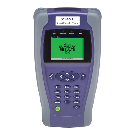
(includes *Action and #Start keys) Backlight key Power key Figure 1 SmartClass front panel The label near the top will say “SmartClass E1/Data”, if you have the E1/Datacomm configuration. The following paragraphs describe each of the controls and LEDs on the front panel. -
Page 23: Status Leds
Auto Config. Amber – At least one error or alarm has occurred since that last reset. – All Summary results are OK. No error or alarm has been received. SmartClass E1 Tester User’s Guide... -
Page 24: Lcd
Power key Use the power key to turn power ON (see “Powering ON your unit” on page 10), put the unit into sleep mode, or turn power OFF (see “Powering OFF your unit” on page 10). SmartClass E1 Tester User’s Guide... -
Page 25: Exploring The Side Panels
Table 5 on page 4 for cables that are available for the SmartClass E1 Tester. The RS232 connector is only used on the SmartClass E1/Datacomm configu- ration. It is used to connect to network elements when using the optional VT-100 emulation feature. -
Page 26: Exploring The Bottom Panel
The following procedure describes how to power ON the E1 Tester. To power ON your unit – Press and hold the Power key for a few seconds. The SmartClass E1 splash screen appears for a few seconds, and then the Main Menu appears. Powering OFF your unit The following procedure describes how to power OFF the E1 Tester. -
Page 27: Navigating The User Interface
Using the LCD and keypad, you can set up the unit, configure test param- eters, and view test results. This section describes the user interface, and explains how to navigate through the menus and screens. When you power up the SmartClass E1 Tester, the Main Menu of the user interface appears. Figure 5 illustrates the Main menu for the SmartClass E1/ Datacom tester. -
Page 28: Menu Screens
Chapter 1 Getting Started Navigating the user interface Menu screens Figure 6 illustrates the Configuration menu screen for the SmartClass E1 tester. Figure 6 SmartClass E1 Tester Configuration menu screen Menu screens provide a series of selections that take you to another menu screen, a data entry screen, or a results screen. -
Page 29: Data Entry Screens
Figure 8 illustrates the Timeslots screen, used to specify the timeslots you want to use to transmit traffic in. Figure 8 SmartClass E1 Tester Data Entry screen Result screens Figure 9 illustrates a Result screen. -
Page 30: Using The Keypad
6 If you want to enter a decimal point, and the setting accepts floating decimal values, press the asterisk (*) key. Typing text To type text 1 Use the arrow keys to scroll to and highlight the setting you want to specify. 2 Press OK. SmartClass E1 Tester User’s Guide... - Page 31 – To scroll through and select a special character such as: . @ / , ‘ - ? ! _ 1 press the 1 (one) key. NOTE You can not enter a space when specifying a filename. SmartClass E1 Tester User’s Guide...
- Page 32 Chapter 1 Getting Started Using the keypad SmartClass E1 Tester User’s Guide...
-
Page 33: Instrument Settings
“Adjusting the contrast and brightness” on page 20 – “Determining the specified battery type” on page 20 – “Managing files” on page 20 – “Setting options” on page 21 – “Restoring factory defaults” on page 21 SmartClass E1 Tester User’s Guide... -
Page 34: Setting The Language
1 Power ON your tester by pressing and holding the key for a few seconds. The SmartClass E1 splash screen appears briefly, and then the SmartClass E1 main menu appears. 2 Select System Settings. A menu appears listing each of the system settings. -
Page 35: Setting The Date And Time
3 Do one of the following: – To set the time, select Set Time, and then enter the time. – To set the date, select Set Date, and then enter the date. The date or time is set. SmartClass E1 Tester User’s Guide... -
Page 36: Adjusting The Contrast And Brightness
– If you want to delete the file, press the left arrow key. A menu appears asking you to verify whether or not you want to delete the file. To delete the file, select Yes. The file is deleted. SmartClass E1 Tester User’s Guide... -
Page 37: Specifying Db9 Port Usage
The Set Options item on the System Settings menu allows you to add optional functionality to your SmartClass E1 Tester. If the options were ordered at the same time the unit was ordered, they will be installed at the factory. If you order a field upgrade, you will receive a package with an option code to enter here, along with additional instructions. - Page 38 Chapter 2 Instrument Settings Restoring factory defaults SmartClass E1 Tester User’s Guide...
-
Page 39: Basic Testing
Topics discussed in this chapter include the following: – “Managing test configurations” on page 24 – “Starting or restarting a test” on page 25 – “Stopping a test” on page 25 – “Timed testing” on page 25 SmartClass E1 Tester User’s Guide... -
Page 40: Managing Test Configurations
2 Select Restore/View. A menu appears listing all saved configurations. 3 Use the up and down arrows to highlight the configuration you want to restore, and then press OK. The configuration is displayed on the screen. SmartClass E1 Tester User’s Guide... -
Page 41: Starting Or Restarting A Test
2 On the Configuration menu, select Timed Test. 3 Select Enabled, and then select either On or Off. 4 Select Duration, and then enter the number of seconds to run the test. The test runs for the specified duration. SmartClass E1 Tester User’s Guide... -
Page 42: Viewing Test Results
Remote Control With the remote control option, you can connect to a E1 Tester in order to control it remotely using command lines via the serial interface. A command guide is available with the option. SmartClass E1 Tester User’s Guide... -
Page 43: E1 Testing
E1 Testing Chapter 4 This chapter provides task-based instructions for turning up and trouble- shooting E1 service using the SmartClass E1 Tester. Topics discussed in this chapter include the following: – “About E1 testing” on page 28 – “Launching an E1 test application” on page 28 –... -
Page 44: About E1 Testing
About E1 testing About E1 testing The SmartClass E1 tester is intended to be used to commission and maintain E1 circuits. Typically this involves out-of-service testing to ensure that the physical layer is clean and there are no problems with network equipment or improper provisioning. -
Page 45: Specifying Test Application Settings
Specifying a test mode The SmartClass E1 can operate in the following test modes: – Terminate Mode: This mode separates the Transmit and Receive side of an E1 path. The received E1 signal is terminated and a completely inde- pendent signal is transmitted. -
Page 46: Configuring Test Settings Automatically
The Action menu appears. 4 On the Action menu, select Auto Configure. The SmartClass E1 will attempt to automatically configure the interface, framing, and pattern. If this attempt fails, the E1 tester will set the framing to Unframed and the pattern to Live. You can also configure the framing and pattern settings manually. -
Page 47: Specifying E1 Framing Settings
Select the framing format for the signal: – PCM31C – PCM31 – PCM30C – PCM30 – Unframed Payload Select the payload: – Bulk: full E1 circuit – n x 64k: individual timeslot(s) from an E1 circuit SmartClass E1 Tester User’s Guide... -
Page 48: Specifying E1 Signaling (Abcd/Sa) Settings
Set the 4-digit idle signaling word. NMFAS (XYXX) Set the 4-digit NMFAS word. 3 If you need to specify other settings for the test, press Cancel to return to the Configuration menu. The E1 signaling settings are configured. SmartClass E1 Tester User’s Guide... -
Page 49: Specifying A Bert Pattern
QRSS Simulates live E1 data. E1 QRSS is a modified 2 pseudorandom pattern that allows a maximum of 15 sequential zeros and 20 sequential ones. 2 -1 pseu- dorandom pattern with 14-zero suppression. SmartClass E1 Tester User’s Guide... - Page 50 Selects a user-defined pattern from 3 to 32 bits long. User Byte Pattern Selects a user-defined pattern from 1 to 64 bytes long. If you selected User Bit Pattern or User Byte Pattern, proceed to step Otherwise, proceed to step SmartClass E1 Tester User’s Guide...
-
Page 51: Specifying Error/Alarm Settings
3 On the Defects/Alarms menu, select one of the following defects or alarms: Defect/Alarm Description Loss of signal Loss of framing Alarm indication signal Remote defect indication MF AIS Multi frame AIS MF RDI Multi frame RDI Proceed to step SmartClass E1 Tester User’s Guide... -
Page 52: Specifying Performance Settings
You can configure settings for ITU performance analysis. This is only available in the E1 BERT application. settings To configure performance settings 1 If you haven’t already done so, launch an E1 BERT test application (see “Launching an E1 test application” on page 28). SmartClass E1 Tester User’s Guide... -
Page 53: Specifying Vf Settings
Specify the VF tones pattern for the signal you want to transmit. Speaker State Specify whether the speaker is turned on or off. Volume Control Use the right or left arrow keys to increase or decrease the speaker volume. SmartClass E1 Tester User’s Guide... -
Page 54: Monitoring A Circuit
– Connect the 2M Reference Clock cable from the SmartClass E1 RX2/ Ext Clk jack to an E1 BITS clock or a known good reference signal. – Connect a cable from the SmartClass E1 RX1/TX1 jack to the signal to be tested. -
Page 55: Measuring Timing Slips
You have finished monitoring the circuit. Measuring timing slips The SmartClass E1 allows you to monitor the timing between two E1 signals for timing slips. For example, you can check customer premises equipment against a master clock at the central office, or you can compare two lines of network equipment. -
Page 56: Terminate Testing
Terminate testing Terminate testing In Terminate mode, you can use the SmartClass E1 to perform bit error rate testing (BERT or BER testing) on E1 circuits, and timeslots within the E1 circuit. You can test for bit errors, code errors, frame errors, and CRC errors (if applicable). -
Page 57: Line Loopback Testing
Settings menu. NOTE: The SmartClass E1 Tester will first attempt to insert a clean code error (with- out a bit error). If, after a time-out period of 256 bits, this is not possible, the unit will insert a code plus a bit error (a line error). This timeout would occur if an unframed all zeros pattern is currently being transmitted. -
Page 58: Pulse Shape Analysis
– Summary displays a large “All Summary Results OK” message if no anomalies or defects have been detected. If anomalies are detected, results are displayed. – Pulse Shape displays a graphical representation of the pulse. SmartClass E1 Tester User’s Guide... -
Page 59: Measuring Jitter
Before running any tests, you should configure the E1 Tester with the appro- priate settings for the line under test. To configure test settings 1 From the E1 Measurement menu, launch the E1 Jitter application. 2 From the E1 Jitter menu, select Configuration. The Configuration menu appears. SmartClass E1 Tester User’s Guide... - Page 60 “Specify- ing a BERT pattern” on page Error/Alarm Settings Specify the settings as described in “Specify- ing Error/Alarm settings” on page Performance Settings Specify the settings as described in “Specify- ing performance settings” on page SmartClass E1 Tester User’s Guide...
-
Page 61: Connecting To The Circuit
– Connect the 2M Reference Clock cable from the SmartClass E1 RX2/ Ext Clk jack to an E1 BITS clock or a known good reference signal. – Connect a cable from the SmartClass E1 RX1/TX1 jack to the signal to be tested. -
Page 62: Testing Mfc-R2 Signaling
Chapter 4 E1 Testing Testing MFC-R2 Signaling Testing MFC-R2 Signaling The SmartClass E1’s MFC-R2 signaling option allows testing of line signaling (supervisory signals) and inter-register signaling (call control signals). NOTE: MFC-R2 Signaling is an optional feature. It only appears if you have pur- chased the MFC-R2 software option. - Page 63 (selectable only for Forward category, from II-1 to II-15. Direction and Express Sequence Generation) Number of DIDs Specify the number of DIDs on the circuit. (selectable only for Back- ward Direction and Express Sequence Generation) SmartClass E1 Tester User’s Guide...
- Page 64 GroupB Rcv Idle Tone Select a timeslot between 0 and 15. 7 Optional. To save the test configuration, Save/Restore-View. For more information on saving test configurations, see “Managing test configura- tions” on page The settings are specified SmartClass E1 Tester User’s Guide...
-
Page 65: Connecting To The Line
– Line Display displays the current line signaling and/or register signaling for each receive channel with its associated time stamp. For more information about R2 results, see “MFC-R2 results” on page You have completed the test. SmartClass E1 Tester User’s Guide... - Page 66 Chapter 4 E1 Testing Testing MFC-R2 Signaling SmartClass E1 Tester User’s Guide...
-
Page 67: Datacom Testing
“Specifying test settings” on page 53 – “Connecting the E1/Datacom Tester to the circuit” on page 61 – “BER Testing” on page 63 – “Monitoring a Datacom interface” on page 64 – “Frame Relay testing” on page 64 SmartClass E1 Tester User’s Guide... -
Page 68: About Data Communications Testing
Chapter 5 Datacom Testing About data communications testing About data communications testing The SmartClass E1/Datacom Tester provides the tools you need to turn up and maintain data services. The Data Communications option offers the following features and capabilities: – End-to-End Testing—Using the E1/Datacom Tester, you can analyze the performance of an entire digital link in both directions, allowing you to isolate problems to a specific direction. -
Page 69: Specifying Test Settings
The datacom application is launched. Specifying test settings Before you begin testing with the SmartClass E1/Datacom Tester, you should specify the characteristics of the circuit that you will connect to the tester. Specifying the test mode You can operate the SmartClass E1/Datacom Tester in three different test modes: Monitor, DTE Emulation, or DCE Emulation. -
Page 70: Specifying Timing Parameters
– DCE Rx Timing (only available in DCE emulation or monitor mode) A menu of timing options appears. 4 Select the appropriate timing. You have finished specifying the clock source for transmit and receive timing. SmartClass E1 Tester User’s Guide... -
Page 71: Specifying Polarity Settings
-1 pseudorandom pattern, which generates a maximum of 5 sequential 0s and 6 sequential 1s. PRBS 511 Selects the 2 -1 pseudorandom pattern, which generates a maximum of 8 sequential 0s and 9 sequential 1s. SmartClass E1 Tester User’s Guide... - Page 72 The Quick Brown Fox message. LUP 1TO1 A one followed by a zero, the minimum stress on clock recovery circuits. LUP 1TO3 A one followed by 3 zeros. LUP 1TO4 A one followed by 4 zeros. SmartClass E1 Tester User’s Guide...
-
Page 73: Specifying Data Parameters
50 Hz to 2.048 Hz RS-449/V.36 Balanced 50 Hz to 10 MHz 1. Can be up to 10 MHz, depending on the cable. See Table 5 on page 4 for more information. You have finished specifying the data rate. SmartClass E1 Tester User’s Guide... -
Page 74: Enabling/Disabling Data Loss Detection
If you selected Asynchronous as the timing mode, you must specify the char- acter format for the data. To specify async settings 1 If you haven’t already done so, launch the Data Communication applica- tion (see “Launching the datacom application” on page 52). SmartClass E1 Tester User’s Guide... -
Page 75: Specifying Flow Control Settings
Out-of-band flow control based on the Request To Send (RTS) signal. CTS/I Out-of-band flow control based on the Clear To Send (CTS) signal. RLSD Out-of-band flow control based on the Receiver Line Signal Detect (DCD) signal. SmartClass E1 Tester User’s Guide... -
Page 76: Specifying G.821 Performance Settings
4 If you selected Multiple, select Error Count and then enter the number of errors to be inserted, between 1 and 50. 5 If you selected Rate, select Error Rate a nd then select the insertion rate. You have finished specifying the error settings. SmartClass E1 Tester User’s Guide... -
Page 77: Performing A Self Test
The following sections describe how to connect the E1/Datacom Tester for monitor or DTE/DCE emulation tests. SmartClass E1 Tester User’s Guide... -
Page 78: Connecting For X.21 Testing
– If the emulation mode is Monitor, use the V.36 Y-Monitor (part number CB-44347). 2 Connect one end of the adaptor cable to the E1/Datacom Tester’s universal Datacom connector located on the top panel of the unit. SmartClass E1 Tester User’s Guide... -
Page 79: Ber Testing
(appears only if the Rate Type is set to “Multiple”). – Bit Error Insert — inserts one bit error with each press (appears only if the Rate Type is set to “Single”). 11 From the BERT menu, select Results and then the BERT category. SmartClass E1 Tester User’s Guide... -
Page 80: Monitoring A Datacom Interface
With the Frame Relay testing feature, results such as LMI message stats, error results, DCLI status, and link trace results are available. Launching the Frame Relay The following procedure describes how to launch the datacom application. application SmartClass E1 Tester User’s Guide... -
Page 81: Configuring The Test Mode
NOTE: Frame Relay is an optional feature. It only appears if you have purchased the frame relay option with the SmartClass E1/Datacom configuration, and is only available over the Datacom interface. A message briefly appears stating that the unit is launching the test application. -
Page 82: Configuring The Frame Load Settings
Load Rate Enter a value, from 1 to 10000 kbps, for the data load rate. (Fixed loads only) Note: It is possible to enter a load rate that exceeds the data rate for the interface. SmartClass E1 Tester User’s Guide... - Page 83 IP address of the equipment at the other end of the Frame Relay link, select On. – Off. If you specified a destination address for the device you are pinging, select Off. Off is the default. SmartClass E1 Tester User’s Guide...
-
Page 84: Configuring The Frame Header Settings
Enter a value, from 0 to 1023, for the received data link E1/Datacom Tester connection identifier (DLCI). The will display test results for the traffic on this DLCI in the DLCI result category; results for the entire link appear in the Link result category. SmartClass E1 Tester User’s Guide... -
Page 85: Configuring The Lmi Settings
For example, if you enter 4, the E1/Datacom Tester will perform a full status poll every 4th time. Interface Select one of the following interfaces: – UNI-U (user) – UNI-N (network) – NNI SmartClass E1 Tester User’s Guide... -
Page 86: Configuring The Trace Settings
3 Select OOB Flow Ctrl, and then select On to enable out of band flow control, if necessary. 4 If you need to specify other settings for the test, press Cancel to return to the Configuration menu. The flow control settings are specified. SmartClass E1 Tester User’s Guide... -
Page 87: Specifying Polarity Settings
5 Specify how link trace results should be displayed. See “Configuring the trace settings” on page 6 Specify the polarity settings. See “Specifying polarity settings” on page 7 After you finish configuring the test settings, press Cancel to return to the Test menu. SmartClass E1 Tester User’s Guide... -
Page 88: Transmitting Traffic Over A Datacom Interface
9 Connect the E1/Datacom Tester to the circuit. For more information, see “Connecting the E1/Datacom Tester to the circuit” on page 10 On the Test menu, select Restart soft key to begin the test. The E1/Datacom Tester transmits frame relay traffic over the Datacom inter- face. SmartClass E1 Tester User’s Guide... -
Page 89: Vt100 Terminal Emulation
This chapter contains information about using the E1/Datacom Tester to emulate a VT100 terminal. Topics discussed in this chapter include the following: – “About VT100” on page 74 – “VT100 cabling” on page 74 – “Emulating a VT100 terminal” on page 74 SmartClass E1 Tester User’s Guide... -
Page 90: About Vt100
Connect one end of the DB-9 cable to the E1/Datacom Tester’s RS-232 connector located on the left panel. b If necessary, connect the other end of the cable to the null modem adapter (DB-9 male to male). c Connect the cable to a network element. SmartClass E1 Tester User’s Guide... - Page 91 7 If the VT100 session does not start after a few seconds, view the File menu and then select 10 Spaces. A VT100 session screen appears. The menu for the network element appears after a few seconds. 8 To view different parts of the screen, use the arrow keys. SmartClass E1 Tester User’s Guide...
- Page 92 Enter a file name, and then press the OK key. You can view the saved file using the File Manager. 12 To exit, press and hold the *Action key, press the 5 key to view the File menu, and then select Exit. SmartClass E1 Tester User’s Guide...
-
Page 93: Test Results
“Jitter results” on page 88 – “MFC-R2 results” on page 90 – “Datacom results” on page 90 – “Frame relay results” on page 94 – “Saving results” on page 101 – “Viewing saved results” on page 101 SmartClass E1 Tester User’s Guide... -
Page 94: E1 Results
Number of times synchronization is lost after pattern sync. Rx Freq Max Dev Receive Frequency Maximum Deviation. This result appears when the deviation from the nominal E1 fre- quency of 2048 kBps is greater than 50 ppm. SmartClass E1 Tester User’s Guide... -
Page 95: Statistics Results
Number of seconds in which LOS was detected Rx Frequency Frequency of the clock recovered from the received E1 circuit Rx Freq Dev PPM Current received frequency deviation, ± 200 ppm Rx Freq Max Dev Maximum received frequency deviation, ± 200 ppm SmartClass E1 Tester User’s Guide... -
Page 96: Interface Results
Ratio of errored FAS bits to the total number of FAS bits received FAS Word Errors Number of errored FAS words detected MFAS Word Errors Number of errored MFAS words received since initial frame sync SmartClass E1 Tester User’s Guide... -
Page 97: Frame Data Results
Number of blocks containing one or more errored bits. Pattern Slips Number of pattern slips detected since start of test (PRBS patterns only) Pattern Slip Seconds Number of seconds during which one or more pattern slips occurred after initial pattern synchronization. SmartClass E1 Tester User’s Guide... -
Page 98: Performance Results
SmartClass E1. Calcu- lated in milliseconds. Performance results The SmartClass E1 provides performance analysis results in accordance with the ITU-T G.821, G.826, and M.2100 standards. The following sections describe the results for each standard. G.821 results Table 15 describes the G.821 performance results. -
Page 99: G.826 Ism Results
Far End CRC Background Block Error. Number of errored blocks that are not SES. FE CRC Far End CRC Background Block Error Ratio. The ratio of avail- BBER able blocks to the number of errored blocks. SmartClass E1 Tester User’s Guide... -
Page 100: G.826 Oos Results
Near End Errored Seconds Ratio. The ratio errored seconds to the number of available seconds. NE SES Near End Severely Errored Seconds. Available seconds during which one or more defects were present or the anomaly block error rate exceeded the ITU-T Rec. M.2100 threshold. SmartClass E1 Tester User’s Guide... -
Page 101: M.2100 Oos Results
Errored Seconds Ratio. The ratio errored seconds to the number of available seconds. Severely Errored Seconds. Available seconds during which one or more defects were present or the anomaly block error rate exceeded the ITU-T Rec. M.2100 threshold. SmartClass E1 Tester User’s Guide... -
Page 102: Vf Results
The Pulse Shape results will only be available if you purchased the Pulse Shape option. For information about purchasing options for the SmartClass E1 Tester, con- tact your JDSU representative or your local JDSU sales office. You can also contact JDSU through the company web site, www.jdsu.com. - Page 103 This is the amount of the leading edge that rises above the 100% point of the waveform. Undershoot This is the amount of the trailing edge that falls below the zero point of the waveform. SmartClass E1 Tester User’s Guide...
-
Page 104: Pulse Shape
The module also allows you to view the jitter results in a graph- ical or tabular format. Summary results The Summary results report the same results as the other E1 tests. See “E1 Summary results” on page SmartClass E1 Tester User’s Guide... -
Page 105: Jitter Results
The Event Log results report the same results as the other E1 tests. See “Event Log” on page Event Histogram The Event Histogram results report the same results as the other E1 tests. See “Event Histogram” on page SmartClass E1 Tester User’s Guide... -
Page 106: Mfc-R2 Results
Rx Async Data Loss Number of receiver synchronization losses resulting from a loss of data. Only valid when the Data Loss setting is enabled and only appears if using asynchronous timing. SmartClass E1 Tester User’s Guide... -
Page 107: Clock Results
Control Signal category. Table 25 Control Signal results Result Definition Rx CTS/I Receiver Clear To Send. Rx DSR Receiver Data Set Ready Rx DCD Receiver Line Signal Detect Rx TM Receiver Test Mode SmartClass E1 Tester User’s Guide... -
Page 108: Data Results
Rx Frame Error Rate Ratio of frame errors to received frames. Rx Char Errors Count of characters containing one or more bit errors. Rx Chars Count of the number of received characters since the last test restart. SmartClass E1 Tester User’s Guide... -
Page 109: Bert Results
Round Trip Delay The current time between transmission and reception of the Delay pattern. The result is given in milliseconds. Only applicable when the BERT pattern is set to Delay. SmartClass E1 Tester User’s Guide... -
Page 110: G.821 Performance Results
Summary results The Frame Relay Summary result category displays a large “All Summary Results OK” message if no anomalies or defects have been detected. If anom- alies are detected, results are displayed. SmartClass E1 Tester User’s Guide... - Page 111 Number of detected violations of the selected encoding method. (G703 interface only) Rx Error Bipolar Data Number of detected bipolar data errors. (G703 interface Count only) Rx Error Bipolar Data Bipolar data errors have been detected. (G703 interface Present only) SmartClass E1 Tester User’s Guide...
-
Page 112: Clock Results
The average number of frame relay frames received per second, since the start of the test (frame count ÷ total seconds). Max Frm Rate Rx The maximum number of frame relay frames received per second, since the start of the test. SmartClass E1 Tester User’s Guide... -
Page 113: Link Results
Link category. These results apply to the entire link. Table 31 Link results Result Definition Link Status Indicates whether the link is up or down. Frm Cnt Rx Count of the total number of frame relay frames detected. SmartClass E1 Tester User’s Guide... - Page 114 Long Frm Count of frame relay frames exceeding the length specified as the long frame threshold. Test Frm Rx Count of the total number of frame relay frames detected for the link. SmartClass E1 Tester User’s Guide...
-
Page 115: Ping Results
– Fragmentation Needed but DF Bit Set – Unknown Network – Unknown Host – TTL Failed During Transit – TTL Failed During Reassembly – Network Prohibited – Host Prohibited – Network TOS – Host TOS – Unknown Error SmartClass E1 Tester User’s Guide... -
Page 116: Lmi Results
(Verbose) or summarized (Simple) decode text in this category (see “Configuring the trace settings” on page 70). Event Log The Event Log category displays the date and time that significant events, errors, or alarms occurred during the course of your test. SmartClass E1 Tester User’s Guide... -
Page 117: Event Histogram
The results appear on the screen. You can also view the results in Excel, using the Download Manager utility. For more information on viewing or printing results with Excel, see the instructions provided with the Download Manager. SmartClass E1 Tester User’s Guide... - Page 118 Chapter 7 Test Results Viewing saved results SmartClass E1 Tester User’s Guide...
-
Page 119: Maintaining The Batteries
WARNING: EXPLOSION HAZARD Only charge nickel metal hydride (NiMH) batteries. Do not charge alkaline batteries. Charging any other type of rechargeable or non-rechargeable (disposable) batteries may cause them to leak, rupture, or explode, causing injuries. SmartClass E1 Tester User’s Guide... -
Page 120: Prolonging Battery Life
To charge the batteries 1 Connect one end of the AC adapter to the connector on the bottom of the E1 Tester. 2 Connect the other end of the AC adapter to an AC power supply. SmartClass E1 Tester User’s Guide... -
Page 121: Replacing The Batteries
Failure to turn the power off before removing the batteries from the E1 Tester could damage internal components and/or corrupt the software. Always power down the unit before removing the batteries. 2 Disconnect the AC adapter. SmartClass E1 Tester User’s Guide... - Page 122 5 Replace the battery compartment door, and secure the door by tightening the screw. 6 Reconnect the AC adapter to the unit and to an AC power supply. 7 Turn the unit ON, and then specify the type of battery you inserted. The batteries are replaced. SmartClass E1 Tester User’s Guide...
-
Page 123: Troubleshooting
Troubleshooting Chapter 9 This chapter describes how to identify and correct problems related to the SmartClass E1 Tester. Topics discussed in this chapter include the following: – “Getting Technical Assistance” on page 108 – “Resolving problems” on page 108 SmartClass E1 Tester User’s Guide... -
Page 124: Getting Technical Assistance
– Datacom testing General testing The following section addresses questions about testing in general using SmartClass E1 or E1/Datacom Testers. Issue Batteries are fully charged, and the external power adapter is attached, but the Batt LED on the unit is red. -
Page 125: E1 Testing
Received NOSIG This happens in the Pulse Run the test again. DATA alarm Shape application when the captured pulse does not fall between the maxi- mum and minimum mask. SmartClass E1 Tester User’s Guide... -
Page 126: Datacom Testing
DTE's signaling leads (DTR, RTS). Check the out of band flow control setting. If flow control is on, a generator hold may be preventing the pattern from being transmitted. SmartClass E1 Tester User’s Guide... -
Page 127: Appendix A Signal Lead Names
DTE and an input at the DCE. As the role of the test instrument changes, the direction of this signal in the connector changes. Table 36 on page 112 provides a cross reference of signal lead names, including signal direction. SmartClass E1 Tester User’s Guide... - Page 128 (From DCE) (not supported) Local Loopback (To DCE) Remote Loopback (To DCE) Test Mode (From DCE) Transmitter Signal Element Timing (From DCE) Transmitter Signal SCTE Element Timing (To DCE) Receiver Signal Ele- ment Timing (From DCE) SmartClass E1 Tester User’s Guide...
-
Page 129: Appendix B Specifications
“Jitter specifications” on page 116 – “Datacom specifications” on page 118 – “Physical specifications” on page 124 – “Environmental specifications” on page 124 – “Power specifications” on page 124 – “Warranty information” on page 125 SmartClass E1 Tester User’s Guide... -
Page 130: E1 Interface Connector Specifications
Table 39 describes the receiver specifications. Table 39 Receiver specifications Parameter Specification Inputs 2 balanced RJ-48 jacks Impedance 120 ohms or bridge (HI-Z) Unbalanced/ 75 ohms via adapter cables -16 to -26 dbB resistive loss Compensation SmartClass E1 Tester User’s Guide... -
Page 131: E1 Circuit Testing Specifications
User Byte Patterns 1 to 64 bytes Live Delay Auto (via Auto Configure) Anomaly (Error) Injection Bit (TSE): Single, rate, multiple Code, CRC, Pattern Slip, E-Bit (REBE): Single FAS: Single, 2, 3, 4 MFAS: Single, 2 SmartClass E1 Tester User’s Guide... -
Page 132: Pulse Shape Specifications
Resolution: 1% of nominal level Overshoot Resolution: 1% of nominal level Signal Level In [V] base-peak Result Categories Summary, LED, Signal, Interface, Frame Data, BERT, Pulse Shape, Time Jitter specifications This section provides jitter specifications for the E1 Tester. SmartClass E1 Tester User’s Guide... -
Page 133: Standards
0.03 UI or 3%, whichever is greater Tx resolution 1/64 UI Tx frequency range (nominal) 20 Hz to100 kHz Range of Tx jitter amplitude (UIpp) 0.1 UI to 5 UI Intrinsic jitter of instrument <0.07 UI SmartClass E1 Tester User’s Guide... -
Page 134: Datacom Specifications
RS-232/V.24 interface. Table 46 RS-232/V.24 pin assignments Signal Description Signal Source CCITT Circuit Signal Ground Transmitted Data Received Data Request to Send Clear to send Data Set Ready Signal Ground SmartClass E1 Tester User’s Guide... -
Page 135: X.21 Pin Assignments
Transmit Data Control Receive Data Indication Signal Element Timing Transmitter SIgnal Element Timing Signal Ground Transmit Data Control Receive Data Indication Signal Element Timing Transmitter Signal Element Timing a. Only used with cables CB-44391 and CB-44345 SmartClass E1 Tester User’s Guide... -
Page 136: Pin Assignments
Clear to Send Transmitted Data Transmit Signal Ele- ment Timing Received Data Receiver Signal Element Timing Local Loopback Request to Send DTE Ready Remote Loopback DCE Ready DTE Ready Transmit Signal Element Timing Test Mode SmartClass E1 Tester User’s Guide... -
Page 137: V.35 Pin Assignments
Received Data V.35 (A Lead) Transmitted Data V.35 (B Lead) Received Data V.35 (B Lead) Receiver Signal V.35 Element Timing (B Lead) Transmitter Signal V.35 Element Timing (A Lead) Transmitter Signal V.35 Element Timing (B Lead) SmartClass E1 Tester User’s Guide... -
Page 138: Rs-449/V.36 Pin Assignments
Indicator Protective Shield Shield Ground Send Data Receive Data Receive Data Clear to Send Data Mode Terminal Ready Receiver Ready Terminal Timing Signal Ground Send Timing Receive Timing Local Loopback Remote Loop- back Test Mode SmartClass E1 Tester User’s Guide... -
Page 139: Signal Lead Names
(From DCE) (not supported) Local Loopback (To DCE) Remote Loopback (To DCE) Test Mode (From DCE) Transmitter Signal Element Timing (From DCE) Transmitter Signal Element SCTE Timing (To DCE) Receiver Signal Element Timing (From DCE) SmartClass E1 Tester User’s Guide... -
Page 140: Physical Specifications
Appendix B Specifications Physical specifications Physical specifications Table 52 provides the physical specifications for the SmartClass E1 tester with batteries. Table 52 Physical specifications Parameter Specification Size (H x W x D) 230 x 120 x 50 mm Weight <2 lbs (1 kg) -
Page 141: Warranty Information
Customer with a refund of all charges paid with respect thereto. JDSU shall have no warranty obligations hereunder if (a) the Software is altered or modified or is merged with other software by Customer or any third SmartClass E1 Tester User’s Guide... - Page 142 MERCHANTABILITY OR FITNESS FOR A PARTICULAR PURPOSE, AS WELL AS THOSE ARISING FROM ANY COURSE OF DEALING, USAGE OR TRADE PRACTICE. UNDER NO CIRCUMSTANCES WILL JDSU BE LIABLE FOR ANY INDIRECT OR CONSEQUENTIAL DAMAGES RELATED TO BREACH OF THIS WARRANTY. SmartClass E1 Tester User’s Guide...
- Page 144 Communications Test and Measurement Regional Sales North America Latin America Asia Pacific EMEA www.jdsu.com Toll Free: 1 800 638 2049 Tel: +55 11 5503 3800 Tel: +852 2892 0990 Tel: +49 7121 86 2222 Tel: +1 240 404 2999 Fax:+55 11 5505 1598 Fax:+852 2892 0770 Fax:+49 7121 86 1222 Fax:+1 240 404 2195...