
Related Manuals for 3Com Baseline 2226-PWR Plus


Summary of Contents for 3Com Baseline 2226-PWR Plus
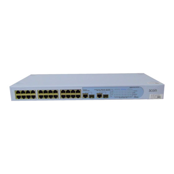
- Page 1 Baseline Switch 2226-PWR Plus (3C16490) User Guide Firmware Version 1.1.0.7 http://www.3com.com/ Part No. DUA1649-0AAA02 Published January 2005...
- Page 2 LICENSE.TXT or !LICENSE.TXT. If you are unable to locate a copy, please contact 3Com and a copy will be provided to you.
-
Page 3: Table Of Contents
ONTENTS BOUT UIDE Conventions Related Documentation Documentation Comments NTRODUCING THE ASELINE Overview of the Baseline Switch 2226-PWR Plus Features and Capabilities Autosensing of MDI/MDIX Connections Autonegotiating 10/100 Mbps Ports Power over Ethernet (PoE) SFP Ports Traffic Prioritization Physical Features Front Panel Rear Panel Package Contents NSTALLING THE... - Page 4 Setting the Traffic Priority IP Phone Prioritization List of Detected Phones PGRADING THE IRMWARE Installing the 3Com TFTP Server Setting Up the 3Com TFTP Server Downloading Firmware Updates Performing Firmware Upgrade ROUBLESHOOTING Resetting to Factory Defaults Forgotten Password Forgotten Static IP Address...
-
Page 5: About This Guide
Most user guides and release notes are available in Adobe Acrobat Reader Portable Document Format (PDF) on the 3Com World Wide Web site: http://www.3com.com Conventions Table 1... -
Page 6: Related Documentation
BOUT UIDE Related Documentation In addition to this guide, each 3Com Baseline Switch 2226-PWR Plus documentation set includes the fol- lowing: Online Help – Accessible from the Web interface, ■ provides information that helps you perform tasks using the Web interface. -
Page 7: Introducing The Baseline Switch
Overview of the Baseline Switch 2226-PWR Plus The 3Com Baseline Switch 2226-PWR Plus is a versa- tile, easy-to-use configurable Switch. It is ideal for users who want the high-speed performance of 10/100 switching with the added functionality of Gigabit links, but do not need sophisticated manage- ment capabilities. -
Page 8: Power Over Ethernet (Poe)
1: I HAPTER NTRODUCING THE Power over Ethernet (PoE) The Switch supports Power over Ethernet (PoE) on all 24 10/100 ports. If you plug in a compatible (IEEE 802.3af compliant) device, the Switch will automati- cally detect and supply power to it. By default, PoE is enabled on all 24 ports. -
Page 9: Physical Features
The 802.1D standard specifies eight distinct levels of priority (0 to 7), each of which relates to a particular type of traffic. The priority levels and their traffic types are shown in Table Table 3 Priority Levels for Traffic Types Priority Level Traffic Type Best effort... - Page 10 1: I HAPTER NTRODUCING THE ASELINE Either shielded or unshielded data cables with shielded or unshielded jacks can be connected to these data sockets. AVERTISSEMENT: Points d’accès RJ-45. Ceux-ci sont protégés par des prises de données. Ils ne peuvent pas être utilisés comme prises de téléphone conven- tionnelles standard, ni pour la connection de l’unité...
- Page 11 (even if the attached device is oper- ating in full-duplex mode). In such a configuration, you may notice some degra- dation of network performance. 3Com recommends that you use devices that are capable of autonegotia- tion (and that you ensure that autonegotiation is enabled, if it is a configurable option).
-
Page 12: Rear Panel
The unit is not receiving power: Verify that the power cord is connected cor- ■ rectly If the unit still does not operate, contact your ■ 3Com network supplier Flashing Power-on self-test is in progress ■ Green Yellow Power-on self-test or loopback test failed. -
Page 13: Package Contents
“Resetting to Factory Defaults” page Package Contents The 3Com Baseline Switch 2226-PWR Plus package includes the following items: One 3Com Baseline Switch 2226-PWR Plus unit ■ One power cord ■ Four standard height, self-adhesive rubber pads ■... - Page 14 1: I HAPTER NTRODUCING THE ASELINE WITCH...
-
Page 15: Installing The Switch
NSTALLING THE This chapter contains information that you need to install and set up the Switch. It covers the following topics: Positioning the Switch ■ Rack-Mounting or Free-Standing ■ Supplying Power to the Switch ■ Connecting a Network Device ■ Connecting a Network Device ■... -
Page 16: Rack-Mounting Or Free-Standing
Airflow around the unit and through the vents in ■ the side of the case is not restricted (3Com recom- mends that you provide a minimum of 25 mm or 1 in. clearance). The air is as free of dust as possible. -
Page 17: Placing Units On Top Of Each Other
Ensure that the power input to your system is clean and free from sags and surges to avoid unforeseen network out- ages. 3Com recommends that you install power con- ditioning, especially in areas prone to black outs, power dips and electrical storms. -
Page 18: Checking For Correct Operation
You will need to reconfigure the Switch after you reset it. If these do not resolve the issue: Check the 3Com Knowledgebase for a solution. To ■ visit the 3Com Knowledgebase Web site, start your Web browser, and then enter http://knowledgebase.3com.com... -
Page 19: Using Sfp Transceivers
■ ■ To access the latest list of approved SFP transceivers for the Switch on the 3Com Corporation World Wide 1000 Mbps copper Web site, enter this URL into your Internet browser: or fiber connection... -
Page 20: Removing An Sfp Transceiver
At frequent intervals, you should visually check the Switch. Regular checks can give you an early warning of a possible failure; any problems can then be attended to when there will be least effect on users. 3Com recommends periodically checking the items listed in Table... - Page 21 Table 5 Items to Check Item Verify That Cabling All external cabling connections are secure and that no cables are pulled taut Cooling fan Where possible, check that the cooling fan is operating by listening to the unit. The fan is fitted on the right side of the unit (when viewed from the front).
- Page 22 2: I HAPTER NSTALLING THE WITCH...
-
Page 23: Onnecting To The
A computer that is connected to the Switch and ■ that has a Web browser Running the Discovery Application The 3Com Baseline Switch 2226-PWR Plus CD-ROM contains, among others, the Discovery application. To use Discovery to connect to the Web interface, do the following: On a computer that is connected to the Switch, insert the CD-ROM into its CD drive. -
Page 24: Logging On To The Web Interface
Switch, and then click Next. If the computer has only one adapter, click Next. Discovery searches the network for 3Com devices. When detection is complete, the Discovered Devices screen displays detected network devices. -
Page 25: Navigating The Web Interface
The logon screen also displays the IP address that the Switch is currently using. Figure 7 Logon Screen To log on to the Web interface: In Username, type admin Leave the Password field blank. Click OK. Navigating the Web Interface The Web interface has been designed to enable you to easily perform advanced configuration tasks and view information about the Switch. -
Page 26: Buttons
Switch. Before you can per- form an upgrade, you first need to download firmware updates from the 3Com Web site. Support Displays 3Com contact information and describes how to use the online help system Log Out Allows you to securely log off the... -
Page 27: Dhcp Assigned Ip Address
DHCP Assigned IP Address If you set the IP address mode to DHCP, check the DHCP server for the IP address that is assigned to the Switch, and then use that IP address to access the Web interface. For example, if the DHCP server assigned the IP address 192.168.0.123 to the Switch, start your Web browser, and then type http://192.168.0.123... - Page 28 3: C HAPTER ONNECTING TO THE NTERFACE...
-
Page 29: Onfiguring The
ONFIGURING THE This chapter provides information on how to config- ure the Switch’s advanced features. Topics include: Changing the Admin Password ■ Modifying the IP Address Settings ■ Configuring Port Settings ■ Configuring VLANs ■ Configuring Link Aggregation ■ Configuring PoE ■... -
Page 30: Changing The Admin Password
MAC address table. This is set to 300 seconds and is not con- figurable. If you request for technical assistance from 3Com Support, you may be asked to print out the informa- tion on this screen. Changing the Admin Password To prevent unauthorized users from accessing the Web interface and modifying the Switch’s settings,... -
Page 31: Modifying The Ip Address Settings
have not previously set a password, leave this field blank. In New Password, type the password that you want to set. In Confirm Password, retype the password you typed in step 3 to confirm. The password is case-sensitive. Click Apply. If you want to modify the admin password later on, follow the same procedure. -
Page 32: Setting The Ip Address
4: C HAPTER ONFIGURING THE 3Com recommends using automatic IP configuration only for the initial setup. Once you gain access to the console, you should assign an IP address to the Switch (either by using DHCP or assigning a static IP address) to ensure successful communication between the Switch and other network devices. -
Page 33: Configuring Port Settings
Configuring Port Settings Using the Web interface, you can configure the speed/duplex and flow control settings of each port. You can also shut down or disable ports from the Web interface. Viewing Port Settings To view the current port settings, click Port Configu- ration on the menu. -
Page 34: Changing A Port's Settings
4: C HAPTER ONFIGURING THE Changing a Port’s Settings If a port is a member of an aggregated link (or trunk), you will not be able to configure its individual port settings. All member ports of an aggregated link will have the same settings, and you can configure these by clicking the AL link on the Port Configuration screen. -
Page 35: Configuring Vlans
Option Description Speed Duplex Sets the preferred speed and duplex mode for the port. This option is only available when autonegotiation for the port is dis- abled. Available speed and duplex modes include: 10Mbps Half ■ 10Mbps Full ■ 100Mbps Half ■... -
Page 36: Creating A Vlan
4: C HAPTER ONFIGURING THE Communication between different VLANs can only take place if they are all connected to a router or layer 3 switch. Creating a VLAN Use the VLANs page to create VLANs on the Switch. To propagate information about VLAN groups used on this Switch to external devices, you must specify a VLAN ID for each VLAN. -
Page 37: Sample Vlan Configurations
For examples on setting up VLANs, refer to VLAN Configurations”. Sample VLAN Configurations To illustrate how you can segment network devices that are connected to the Switch, the following sample configurations are provided. Setting Up Two VLANs on the Same Switch Figure 16 illustrates how you can set up a simple VLAN on the Switch using desktop connections. -
Page 38: Removing A Vlan
4: C HAPTER ONFIGURING THE WITCH Figure 17 Uplink VLAN Configuration Endstation in VLAN 1 (Desktop) Server in VLAN 1 (Desktop) Endstation in VLAN 2 (Desktop) Switch 1 Port 16 in VLANs 1 and 2 (Uplink) Switch 2 Port 8 in VLANs 1 and 2 (Uplink) Endstation in VLAN 2 (Desktop) -
Page 39: Trunk Membership
The Switch does not support the Link Aggregation Control Protocol (LACP), which is specified in IEEE 802.3ad. Trunk Membership The Switch has four pre-defined trunks, each of which can support up to eight ports. possible membership groups for each trunk. Table 11 Port Groups and Members Port Group Ports... -
Page 40: Configuring Trunk Settings
4: C HAPTER ONFIGURING THE CAUTION: If you try to add a port to a trunk and the speed setting of the port to be added does not match that of the trunk, an error message appears and port will not be added to the trunk. Configuring Trunk Settings Ports that are members of the same trunk will have the same speed/duplex, autonegotiation, and flow... -
Page 41: Configuring Poe For Individual Ports
Figure 20 PoE Configuration Summary Screen You can configure two basic PoE settings in the Switch Configuration section: Power ■ Power Exceed Shutdown Method ■ Table 12 describes the available options for these set- tings. Table 12 Basic PoE Options Option Description Power... - Page 42 4: C HAPTER ONFIGURING THE WITCH To configure the PoE settings of a port: On the PoE Configuration screen, click the port number that you want to configure. The PoE Setting screen appears. Figure 21 PoE Setting Screen Configure the PoE settings of the selected port, including: Power ■...
-
Page 43: Planning Power Budgets
Click Apply to save the PoE settings for the port. To configure the PoE settings of another port, click the port number from the PoE Configuration screen. Planning Power Budgets As you connect more PoE devices to the Switch, you may need to calculate your power budget. -
Page 44: Monitoring Traffic
4: C HAPTER ONFIGURING THE WITCH Figure 22 Statistics Screen Figures that appear onscreen indicate the number of packets transmitted (Tx) and received (Rx). To reset all packet counts to zero, click Clear ■ Counters. To view detailed statistics for each port, click the ■... -
Page 45: Setting The Traffic Priority
toring, the Switch takes all the traffic going in and out of the monitor port and copies it to the analysis port. CAUTION: The analysis port (Mirror From) should have a higher bandwidth than the monitor port (Mir- ror From). Otherwise, the Switch may not be able to copy all traffic effectively during periods of high traf- fic. -
Page 46: Ip Phone Prioritization
4: C HAPTER ONFIGURING THE IP Phone Prioritization Use the IP Phone Prioritization section to enable or disable traffic prioritization for NBX or other IP phones. Table 14 lists the available options for this section. CAUTION: To ensure that the Switch recognizes the NBX or other IP phone during phone initialization, do not connect any data source to the phone until the phone has finished booting up. -
Page 47: Upgrading The Firmware
To perform firmware upgrade, you need to use the 3Com TFTP Server, an application that is included on the Baseline Switch 2226-PWR Plus CD-ROM. 3Com TFTP Server is a simple, streamlined form of FTP without its security features (such as directory listings, password protection, and user authentication). -
Page 48: Setting Up The 3Com Tftp Server
Read the license agreement, and then click Yes to agree. The Choose Destination Location screen appears. To install the 3Com TFTP Server to the default folder, click Next. To specify another location, click Browse, and then select a new location. Click OK, and then click Next. -
Page 49: Performing Firmware Upgrade
Take note of the version number in Current Firmware Version. You will need this information to verify that the upgrade was successfully completed. In TFTP Server IP, type the IP address of the 3Com TFTP Server. “Setting Up the file. You will need this... - Page 50 5: U HAPTER PGRADING THE IRMWARE Figure 28 Status Column Indicates When Upgrade is Complete To verify that the upgrade was successful, access the Web interface, and then go to the System Upgrade screen. The Current Firmware Version should show the version of the firmware that you have just installed.
-
Page 51: Troubleshooting
Switch, with suggested courses of corrective action to take. If you encounter an issue that is not listed here and you cannot solve it, check the 3Com Knowledgebase http://knowledgebase.3com.com your local technical support representative. -
Page 52: Forgotten Password
The fiber cable is in good condition. ■ The SFP module is correctly inserted. ■ A 3Com SFP module is being used. Refer to ■ “Approved SFP Transceivers” on page 19 details. The equipment at the far end is installed and cor- ■... -
Page 53: Solving Power Issues
A PoE device is plugged in, but the PoE LED for the port is off. If a device is not supplied with power after you have connected it to the Switch 2226-PWR Plus, check the following: The power budget for the Switch (180 watts) has ■... -
Page 54: Solving Corrupted Firmware
When the firmware is corrupted, the Switch automat- ically goes into Fail-Safe mode. To upgrade a corrupted firmware: Download the latest firmware from the 3Com Web site to the computer that you are using to access the Web interface. Access the Web interface. The Fail-Safe Mode screen... -
Page 55: Upport For Your Product
Contact your authorized 3Com reseller or 3Com for a complete list of the value-added services available in your area. Troubleshoot Online You will find support tools posted on the 3Com web site at 3Com Knowledgebase helps you troubleshoot 3Com products. This query-based interactive tool is... -
Page 56: Telephone Technical Support And Repair
RODUCT , or under Contact Us To send a product directly to 3Com for repair, you must first obtain a return authorization number (RMA). Products sent to 3Com, without authorization numbers clearly marked on the outside of the pack- age, will be returned to the sender unopened, at the sender’s expense. - Page 57 Thailand 001 800 611 2000 You can also obtain support in this region using the following e-mail: apr_technical_support@3com.com Or request a repair authorization number (RMA) by fax using this number: +65 543 6348 Europe, Middle East, and Africa Telephone Technical...
- Page 58 A: O PPENDIX BTAINING UPPORT FOR Country Telephone Number Antigua 1 800 988 2112 Argentina 0 810 444 3COM Aruba 1 800 998 2112 Bahamas 1 800 998 2112 Barbados 1 800 998 2112 Belize 52 5 201 0010 Bermuda...
-
Page 59: B Safety Information
AFETY Important Safety Information Please read the following safety information carefully before installing the 3Com Baseline Switch 2226-PWR Plus. WARNING: Installation and removal of the unit must be carried out by qualified personnel only. WARNING: If installing the Switch unit in a stack with other units, the Switch unit must be installed below the narrower units and above the deeper units. -
Page 60: Consignes Importantes De Sécurité
B: S PPENDIX AFETY NFORMATION Switzerland The supply plug must comply with SEV/ASE 1011. The supply plug must comply with ■ BS1363 (3-pin 13-amp) and be fitted with a 5 A fuse which complies with BS1362. The mains cord must be <HAR> or ■... -
Page 61: Wichtige Sicherheitshinweise Informationen
WARNUNG: Die Installation und der Ausbau des Geräts darf nur durch Fachpersonal erfolgen. WARNUNG: Wenn der Baseline Switch 2226-PWR Plus mit anderen 3Com Hubs oder Switche gestapelt werden soll, müssen grössere Geräte unter den schmaleren Hubs eingebaut werden. WARNUNG: Das Gerät muß an eine geerdete Steck- dose angeschlossen werden, welche die internation- alen Sicherheitsnormen erfüllt. -
Page 62: Información De Seguridad Importante
B: S PPENDIX AFETY NFORMATION WARNUNG: Die Netzsteckdose muß in der Nähe des Geräts und leicht zugänglich sein. Die Stromversor- gung des Geräts kann nur durch Herausziehen des Gerätenetzkabels aus der Netzsteckdose unterbro- chen werden. WARNUNG: Der Betrieb dieses Geräts erfolgt unter den SELV-Bedingungen (Sicherheitskleinstspannung) gemäß... - Page 63 punto de conexión secundario etiquetado como neutro conectado directamente a tierra. †Impédance à la terre. ADVERTENCIA: Conjunto de cables eléctricos Debe estar homologado para el país donde se utilice. EE.UU. y El conjunto de cables debe estar ■ Canadá homologado por UL y tener la certificación CSA.
-
Page 64: Importanti Informazioni Di Sicurezza
B: S PPENDIX AFETY NFORMATION ADVERTENCIA: El uso de controles, ajustes de ren- dimiento o procedimientos distintos a los especifica- dos en este documento puede producir emisiones de láser peligrosas. Importanti Informazioni di Sicurezza AVVERTENZA: Le operazioni di installazione e rimozione dell'unità... - Page 65 Danimarca La spina di alimentazione deve essere ■ conforme alla sezione 107-2-D1, standard DK2-1a o DK2 Svizzera La spina di alimentazione deve essere ■ conforme SEV/ASE 1011 AVVERTENZA: Le porte RJ-45 sono prese dati RJ-45 schermate. Non è pertanto possibile utilizzarle come normali prese telefoniche né...
- Page 66 B: S PPENDIX AFETY NFORMATION...
-
Page 67: Related Standards
ECHNICAL Related Standards The 3Com Baseline Switch 2226-PWR Plus has been designed to the following standards: Functional ISO 8802-3, IEEE 802.3 (Ethernet), IEEE 802.3u (Fast Ethernet), IEEE 802.3ab and IEEE 802.3z (Gigabit Ethernet), IEEE 802.3x (Flow Con- trol), IEEE 802.1D 1998 (Bridging) - Page 68 C: T PPENDIX ECHNICAL NFORMATION...
-
Page 69: Glossary
LOSSARY 10BASE-T The IEEE specification for 10 Mbps Ethernet over Cat- egory 3, 4 or 5 twisted pair cable. 100BASE-TX The IEEE specification for 100 Mbps Fast Ethernet over Category 5 twisted-pair cable. 1000BASE-LX IEEE 802.3z specification for Gigabit Ethernet over 9/125 micron core single-mode fiber cable. - Page 70 LOSSARY category 5e cables One of five grades of Twisted Pair (TP) cabling defined by the EIA/TIA-568 standard. Category 5e can be used in Ethernet (10BASE-T), Fast Ethernet (100BASE-TX) and Gigabit Ethernet (1000BASE-T) networks, and can transmit data at speeds of up to 1000 Mbps.
- Page 71 standard way for VLANs to communicate across switched networks. IEEE 802.1p An IEEE standard for providing quality of service (QoS) in Ethernet networks. The standard uses packet tags that define up to eight traffic classes and allows switches to transmit packets based on the tagged pri- ority value.
- Page 72 LOSSARY network A network is a collection of computers and other computer equipment that are connected for the pur- pose of exchanging information or sharing resources. Networks vary in size, some are within a single room, others span continents. ping Packet Internet Groper.
- Page 73 TCP relates to the content of the data travelling through a network — ensuring that the information sent arrives in one piece when it reaches its destina- tion. IP relates to the address of the end station to which data is being sent, as well as the address of the destination network.
- Page 74 LOSSARY...
-
Page 75: Index
NDEX Numbers 1000BASE-LX 69 1000BASE-SX 69 1000BASE-T 69 100BASE-TX 69 10BASE-T 69 3Com TFTP Server setting up 48 3CSom TFTP Server installing 47 auto IP configuration 31 default IP address 31 default mask 31 autonegotiation 7, 34 autosensing 7 bandwidth 69... - Page 76 NDEX mounting kit contents 15 using 16 network analyzer 44 network cables category 3 69 category 5 69 category 5e 70 category 6 70 network defined 72 package contents 13 panels front 9 rear 12 password changing 30 default (blank) 30 setting 30 physical features 9 configuring 40...
- Page 77 EGULATORY OTICES FCC S TATEMENT This equipment has been tested and found to comply with the limits for a Class A digital device, pursuant to part 15 of the FCC rules. These limits are designed to provide reasonable protection against harmful interference when the equipment is operated in a commercial environment.